RIPPLE DETECTED NORMAL
EXCESS RIPPLE DETECTED
English
- 13 -
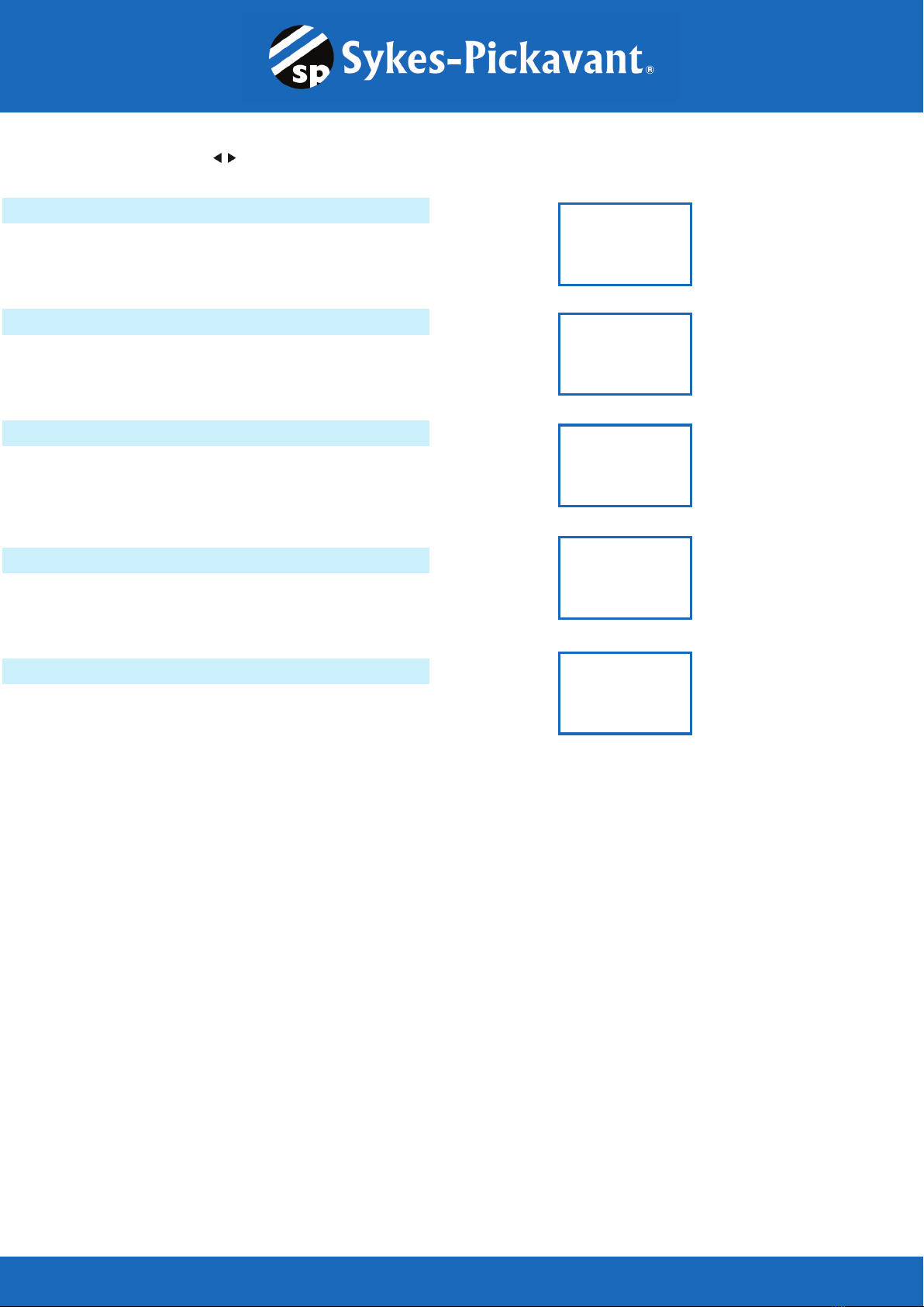
7. Following the charging system at idle, press
«ENTER» for the charging system with accessory
loads. Turn on the blower to high (heat), high beam
headlights, and rear defogger (If equipped). Do not
use cyclical loads such as air conditioning or windshield wipers.
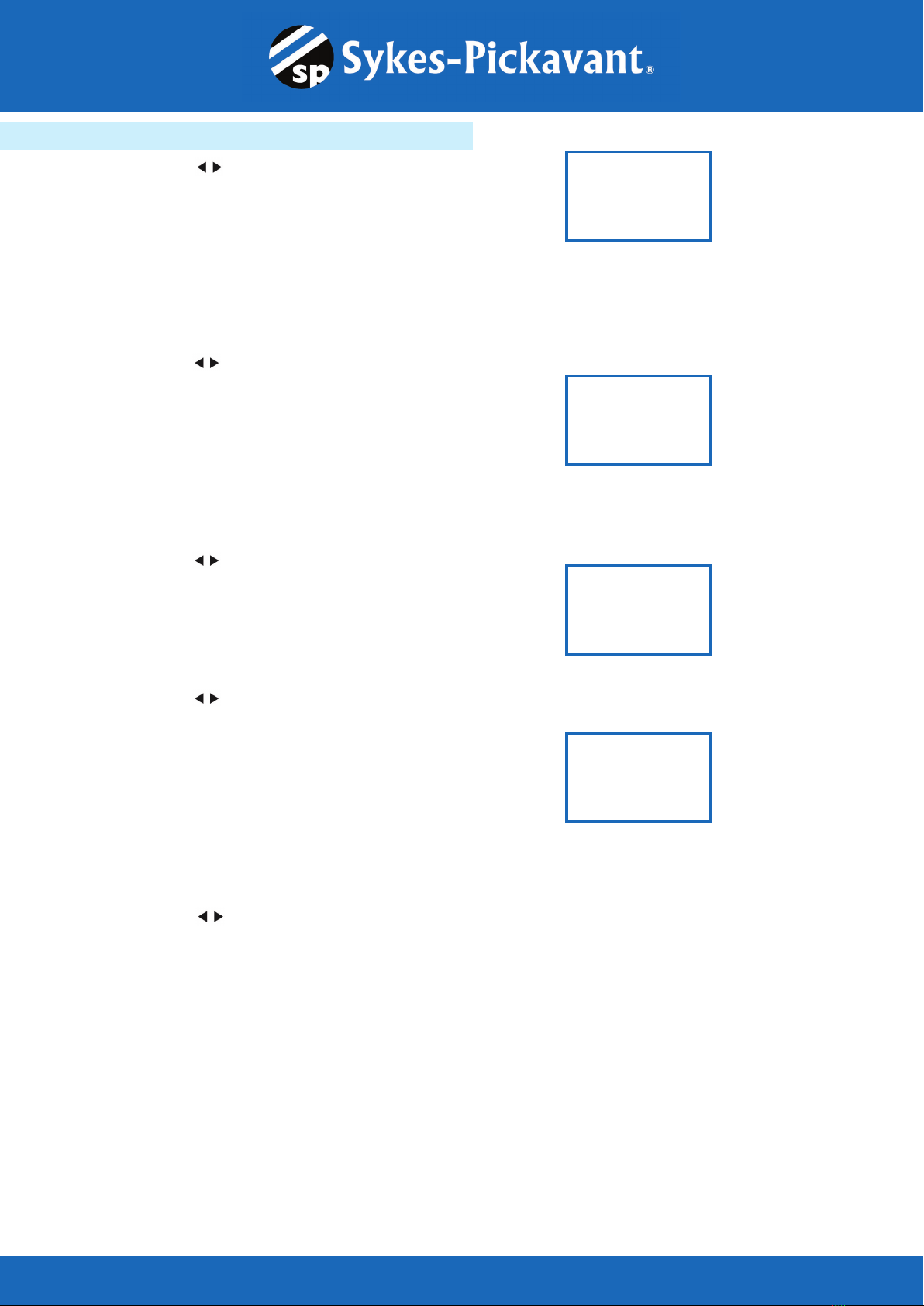
8. When testing older model diesel engines, the
users need to run up the engine to 2500 rpm for
15 seconds. You will view the screen as follows:
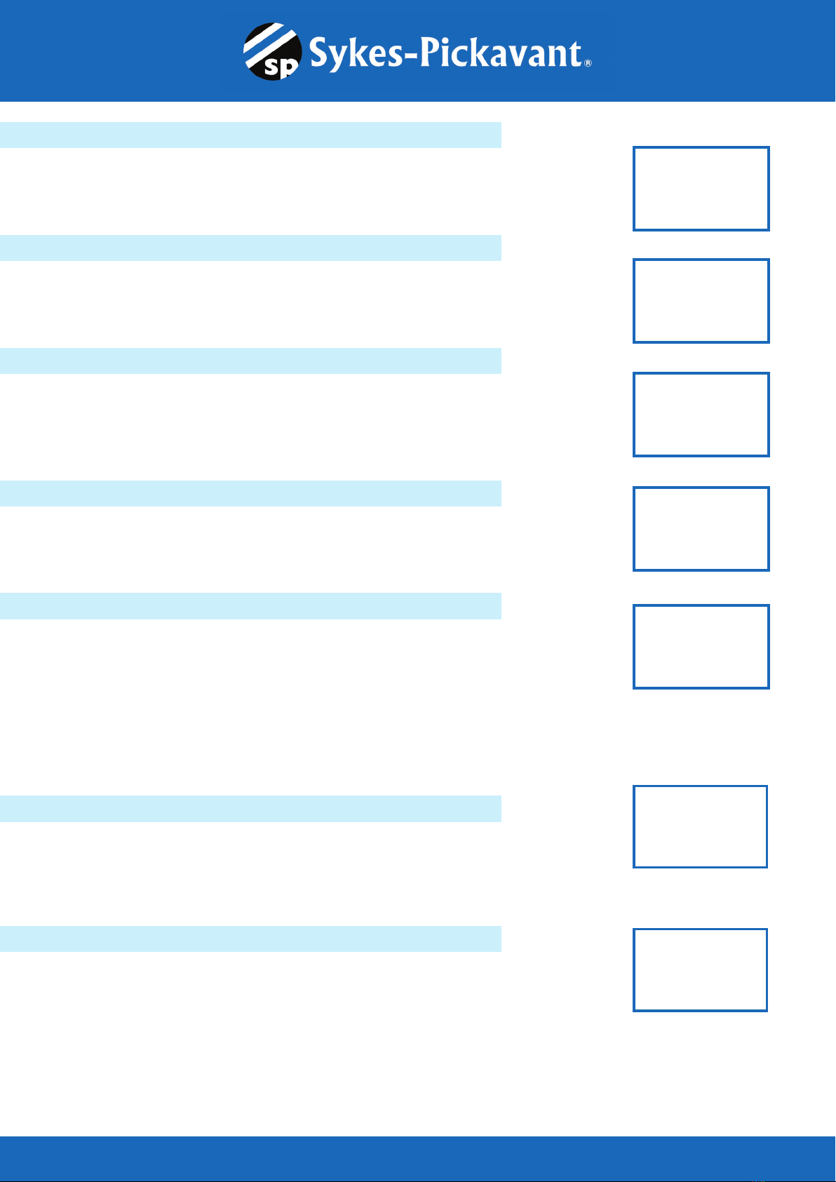
9. Press «ENTER» to look for the amount of ripple from the charging
system to the battery. One of two testing results will be displayed
along with the actual testing measured.
RIPPLE DETECTED NORMAL
Diodes function well in the alternator / stator.
EXCESS RIPPLE DETECTED
One or more diodes in the alternator are not
functioning or there is stator damage. Check to ensure the alternator
mounting is sturdy and that the belts are in good shape and
functioning properly. If the mounting and belts are good, replace the
alternator.
TURN ON LOADS
AND PRESS ENTER
RUN ENGINE UP TO
2500 RPM 15 SEC.
OR
RIPPLE DETECTED
XX.XXV NORMAL
NO RIPPLE DETECT
RIPPLE DETECTED
XX.XXV HIGH
English
- 13 -
7. Following the charging system at idle, press
«ENTER» for the charging system with accessory
loads. Turn on the blower to high (heat), high beam
headlights, and rear defogger (If equipped). Do not
use cyclical loads such as air conditioning or windshield wipers.
8. When testing older model diesel engines, the
users need to run up the engine to 2500 rpm for
15 seconds. You will view the screen as follows:
9. Press «ENTER» to look for the amount of ripple from the charging
system to the battery. One of two testing results will be displayed
along with the actual testing measured.
RIPPLE DETECTED NORMAL
Diodes function well in the alternator / stator.
EXCESS RIPPLE DETECTED
One or more diodes in the alternator are not
functioning or there is stator damage. Check to ensure the alternator
mounting is sturdy and that the belts are in good shape and
functioning properly. If the mounting and belts are good, replace the
alternator.
TURN ON LOADS
AND PRESS ENTER
RUN ENGINE UP TO
2500 RPM 15 SEC.
OR
RIPPLE DETECTED
XX.XXV NORMAL
NO RIPPLE DETECT
RIPPLE DETECTED
XX.XXV HIGH
OR
CHARGING SYSTEM HIGH WHEN TEST WITH ACC. LOADS
CHARGING SYSTEM LOW WHEN TEST WITH ACC. LOADS
CHARGING SYSTEM NORMAL WHEN TEST WITH ACC. LOADS
English
- 14 -
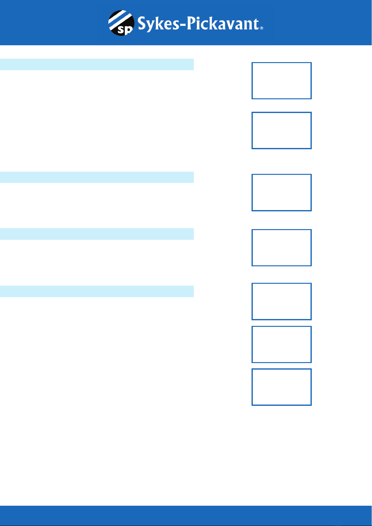
10. Press the «ENTER» key to continue the charging system with
accessory loads. One of the three results will be displayed along with
the actual testing measured.
CHARGING SYSTEM HIGH WHEN TEST WITH ACC. LOADS
The voltage output from the alternator to the
battery exceeds the normal limits of a functioning
regulator. Check to ensure there are no loose
connections and that the ground connection is
normal. If there are no connection issues, replace the regulator.
Since most alternators have the regulator built-in, this will require
you to replace the alternator.
CHARGING SYSTEM LOW WHEN TEST WITH ACC. LOADS
The alternator is not providing sufficient current for
the system’s electrical loads and the charging
current for the battery. Check the belts to ensure
the alternator is rotating with the engine running. If
the belts are slipping or broken, replace the belts and retest. Check
the connections from the alternator to the battery. If the connection is
loose or heavily corroded, clean or replace the cable and retest. If the
belts and connections are in good working condition, replace the
alternator.
CHARGING SYSTEM NORMAL WHEN TEST WITH ACC. LOADS
The system is showing normal output from the
alternator. No problem detected.
ALT. LOAD VOLTS
XX.XXV HIGH
ALT. LOAD VOLTS
XX.XXV LOW
ALT. LOAD VOLTS
XX.XXV NORMAL
English
- 14 -
10. Press the «ENTER» key to continue the charging system with
accessory loads. One of the three results will be displayed along with
the actual testing measured.
CHARGING SYSTEM HIGH WHEN TEST WITH ACC. LOADS
The voltage output from the alternator to the
battery exceeds the normal limits of a functioning
regulator. Check to ensure there are no loose
connections and that the ground connection is
normal. If there are no connection issues, replace the regulator.
Since most alternators have the regulator built-in, this will require
you to replace the alternator.
CHARGING SYSTEM LOW WHEN TEST WITH ACC. LOADS
The alternator is not providing sufficient current for
the system’s electrical loads and the charging
current for the battery. Check the belts to ensure
the alternator is rotating with the engine running. If
the belts are slipping or broken, replace the belts and retest. Check
the connections from the alternator to the battery. If the connection is
loose or heavily corroded, clean or replace the cable and retest. If the
belts and connections are in good working condition, replace the
alternator.
CHARGING SYSTEM NORMAL WHEN TEST WITH ACC. LOADS
The system is showing normal output from the
alternator. No problem detected.
ALT. LOAD VOLTS
XX.XXV HIGH
ALT. LOAD VOLTS
XX.XXV LOW
ALT. LOAD VOLTS
XX.XXV NORMAL