5
COMPLEX SYSTEMS INCLUDING XENON AND BI-XENON HEADLIGHT
SYSTEMS
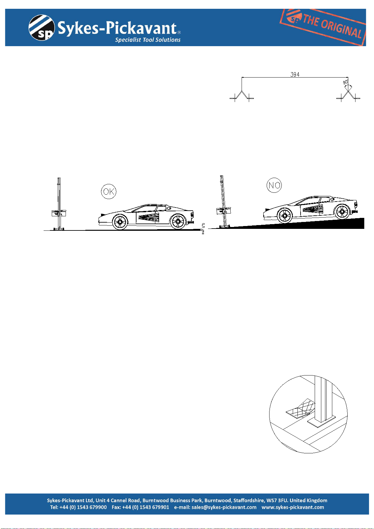
It is essential that this equipment is aligned exactly on the centre line of the dipped beam
pocket.
If when carrying out a normal test/adjustment a clearly defined headlamp pattern cannot be
seen, it will be necessary to move the vehicle closer to the test equipment.
It is essential that the vehicle headlamp and test equipment are as close together as possible.
TESTING HEADLAMPS WITH COMPLEX LENS SYSTEMS.
Complex headlamp systems are those that have more than one lamp behind a single lens.
It is essential that the headlamp aim test equipment is aligned exactly on the centre of the
dipped beam pocket.
If when carrying out a normal test a clearly defined headlamp pattern cannot be seen, it will
be necessary to move the vehicle closer to the test equipment.
It is essential that the car headlamp and test equipment are as close together as possible,
otherwise the whole of the beam pattern may not be visible.
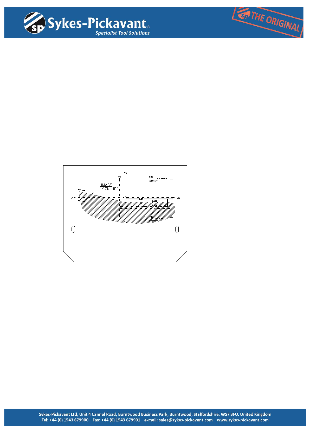
EUROPEAN TYPE HEADLAMP CHARACTERISTICS (NOTE:1)
An asymmetric dipped beam, pattern with a distinctive horizontal cut-off on the right, and a
15 degree wedge of light above the horizontal (the “Kick up”) towards the left.
A lens with one or more asymmetric stepped patterns molded in the glass.
A lens may carry:
European approval mark – a circle containing an “E” and a number, or
Rectangle containing an “e”, and a number
The European approval mark should incorporate a single or double-headed arrow.
The dipped beam is denoted by either:
Capital letter “C” above a capital “E”
Capital letter “C” above an “e”
NOTE: Setting “E” Beam Headlamp aim
These dip-beam headlamps should be set to aim downwards the amount shown on a
marking which is either close to the vehicle manufacturer’s plate or the headlamp.
For vehicles without a marking, the downward aim should be set as follows:
1,3%, if the headlamp centre is not more than 850mm from the ground
2.0%, if the headlamp centre is more than 850mm from the ground
Reason for rejection
The beam image “Kick-up” is to the offside.