manuals.online logo
Brands
  1. Home
  2. •
  3. Brands
  4. •
  5. SymCom
  6. •
  7. Diagnostic Equipment
  8. •
  9. SymCom 355 User manual

SymCom 355 User manual

INSTALLATION INSTRUCTIONS FOR SYMCOM’S
MOTORSAVER MODEL 355
BE SURE POWER IS DISCONNECTED PRIOR TO INSTALLATION!!
FOLLOW NATIONAL, STATE AND LOCAL CODES!
CONNECTIONS
1. Mount the MotorSaver in a convenient location in or near the motor control panel. If the location is
wet or dusty, then MotorSaver should be mounted in a NEMA 4 or 1 enclosure.
. Connect the three lines of the motor's three-phase power to L1, L and L3 on MotorSaver’s terminal
strip (see Figure No. 1).
3. Connect the output relay to the circuitry to be controlled (see Figure No. 1).
(A) To control a motor: Connect the normally open contact in series with the magnetic coil of the
motor starter as shown in Figure No. 1(A).
(B) To sound an alarm: Connect the normally closed contact in series with the alarm as shown in
Figure No. 1(B).
FIGURE NO. 1: TYPICAL WIRING DIAGRAMS
Phone: 800.894.0412 - Fax: 888.723.4773 - Web: www.clrwtr.com - Email: [email protected]
SETTINGS
1. LINE VOLTAGE ADJUSTMENT: Rotate the LINE VOLTAGE ADJUSTMENT to the nominal
three-phase line voltage feeding the motor to be protected.
. RESTART delay: Rotate the RESTART delay to the desired position. The restart delay is the time
between MotorSaver seeing acceptable power and MotorSaver closing its output contacts. For
compressor applications, the restart delay should be set for the approximate time it takes for the
head pressure to bleed off of the compressor. For other applications, the restart delay is typically
set at seconds.
The manual position on the restart adjustment can be used as a manual reset after any fault
condition, or loss of incoming power. To utilize this feature, rotate the restart adjustment to " " and
allow the run light to come on steady. Then rotate the restart adjustment back to the manual mode.
If a power fault occurs after this sequence, the unit will remain off with the corresponding fault light
on until the restart delay is removed from the manual position.
3. UNBALANCE TRIP: Rotate the UNBALANCE TRIP to the desired voltage unbalance trip level.
The NEMA MG1 standard does not recommend operating a motor above a 1% voltage unbalance
as determined by the following formula without derating the motor.
% Voltage Unbalance = [(Maximum Deviation from the Average) / Average] x 100%
The NEMA MG1 standard also recommends against operating a motor above a 5% voltage
unbalance under any circumstances. Therefore, a 5% setting on "UB" is a good place to start but
SymCom recommends consulting the motor manufacturer for specific tolerances.
4. TRIP DELAY ADJUSTMENT: Rotate the TRIP DELAY ADJUSTMENT to the desired setting. The
adjustment does not affect the trip delay on a single-phasing fault. Typically, the TRIP DELAY
ADJUSTMENT is set to 4 seconds. In areas where voltage fluctuations are frequent, the TRIP
DELAY ADJUSTMENT may be set between 10 and 0 seconds.
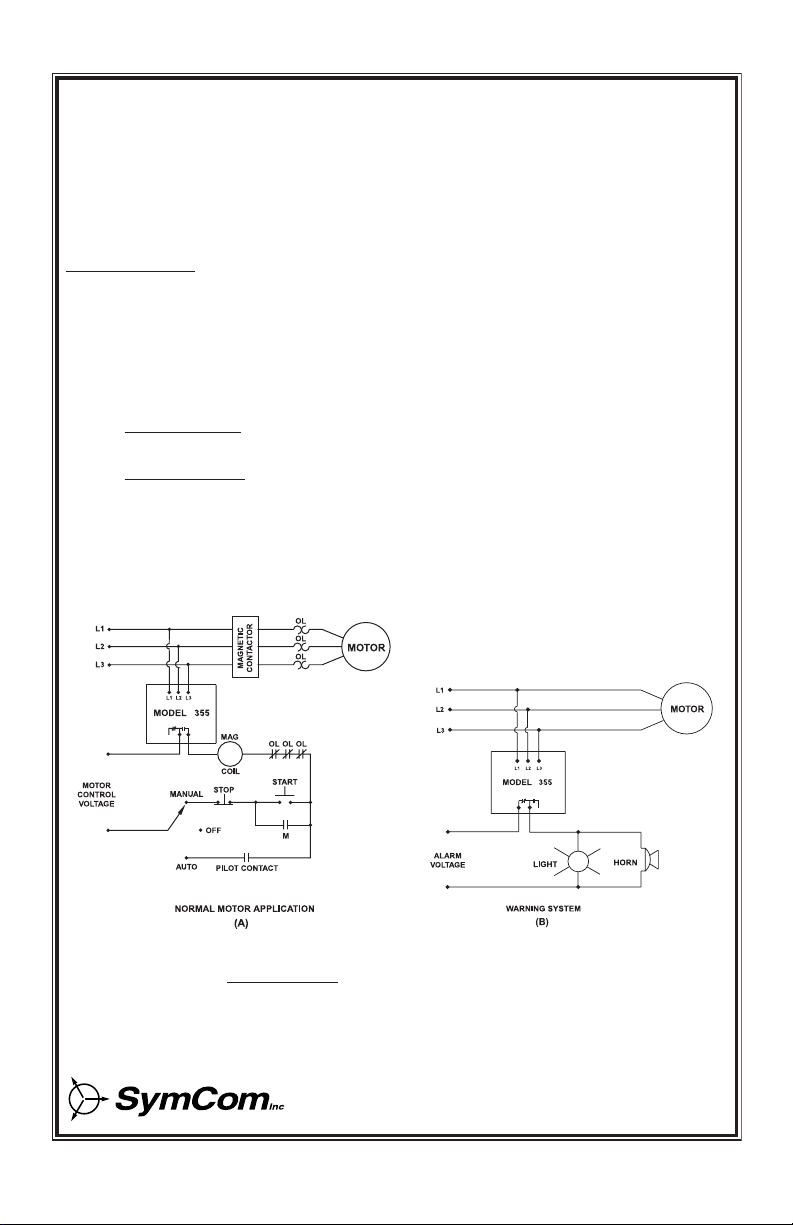
POWER-UP
Turn on the power to the motor. The green RUN LIGHT will blink during the RESTART delay. After the
RESTART delay, MotorSaver will energize its output contacts and the green RUN LIGHT will light. If the
contacts do not energize and the RUN LIGHT does not light, then see the Trouble-Shooting section.
VOLT. ADJ.
(VAC)
UNBALANCE
TRIP (NEMA %)
8
2
38 48
46
44416
4
5
3
3
1
2
2
15
SymCom. Inc.
Rapid City, SD
L1 L2 L3
38 -48 VAC, 3Ø, 5 /6 HZ
MODEL 355
OVER
VOLT.
PHASING
FAULT
UNDER
VOLT.
RUN
PILOT DUTY RATING
47 VA AT 6 VAC
MAN
TRIP
DELAY
(SEC)
RESTART
(SEC)
Phone: 800.894.0412 - Fax: 888.723.4773 - Web: www.clrwtr.com - Email: [email protected]
TROUBLESHOOTING
MOTPMYSNOITULOS
knilbtonseodTHGILNUR lladnapu-rewoplaitinino .noerasthgiltluafeerht
ottessiYALEDTRATSERehtfI.tnemtsujdaYALEDTRATSERkcehC TRATSERehtnruT.edomtratserlaunamnisi553ledoMeht,"NAM" .esolcstcatnoctuptuoehtlitnusdnoceslarevesrof"2"otYALED
tinuehT.tilerasDELoN .daedyletelpmocsmees
woleberasegatlovehtfoynafI.segatlovenil-ot-enileerhtehterusaeM stietarepootrewophguoneevahtonseod553ledoMeht,CAV051 ehtfI.metsysdesahp-elgnisanoruccoyamsihT.scinortcelelanretni .8488-348-008-1@moCmySllac,tcerrocerasegatlov
sithgilTLUAFGNISAHP laitininogniknilb .purewopnoitallatsni
ledoMehtgnirewopsdaelowtynapawS.rewopesahp-eerhtehtffonruT 3Ldna2L,1Lgnitcennocfoecnahc05-05aevahuoY.3Lro2L,1L:553 .rewopesahp-eerhtehtnonruT.emittsrifehtyltcerrocpu
sithgilTLUAFGNISAHP sahrotomehtretfagniknilb .gninnurylsuoiverpneeb
gnimocniowtynapawS.desahpesreverneebevahsenilgnimocniehT .rotcatnoccitengamehtotsenilrewop
thgilTLUAFGNISAHPehT tonlliwtinuehtdnanosi ehthguohtneveteser nitonsiYALEDTRATSER .noitisop"NAM"eht
ehtdeecxesegatlovehtfI.segatlovtcerrocrofsenilgnimocnierusaeM sahnoitidnocesahpelgnis/ecnalabnunaneht,gnittesecnalabnuAMEN llac,wodniwteserehtnihtiwsiecnalabnuegatlovehtfI.derrucco .8488-348-008-1@moCmyS
roTLOVREDNUehT .nosithgilTLOVREVO
eerhtehtfoegarevaehtetaluclaC.segatlovenil-ot-enileerhtehterusaeM ybtessaegatlovlanimonehtfo%7–foedistuosiegarevaehtfI.segatlov fI.ylreporpgninoitcnufsi553ledoMehtneht,TSUJDAEGATLOVENIL 8488-348-008-1@moCmySllac,wodniwteserehtnihtiwsiegatloveht
INDICATOR LIGHTS
ROTACIDNIDELNOITIDNOC
nOEGATLOVREDNU ENILehtnotessaegatlovlanimonfo%39nahtsselegatloV .TSUJDAEGATLOV
nOEGATLOVREVO ENILehtnotessaegatlovlanimonfo%701nahtretaergegatloV .TSUJDAEGATLOV
nOTLUAFGNISAHP PIRTECNALABNUfognittesehtnahtretaergsiecnalabnuegatloV .derruccosahtluafgnisahp-elgnisaro
gniknilBTLUAFGNISAHP.desahp-esreversirewopgnimocnI
REVO,EGATLOVREDNU GNISAHPdnaEGATLOV nOSTHGILTLUAF .noitisoptratserlaunamehtnipuderewopneebsahtinU
nOTHGILNUR.dezigrenesitcatnoctuptuO
gniknilBTHGILNUR.tuognimitsiYALEDTRATSER
Phone: 800.894.0412 - Fax: 888.723.4773 - Web: www.clrwtr.com - Email: [email protected]
SPECIFICATIONS MODEL 355
3-Phase Line Voltage 190 - 40, 380 - 480
(specify voltage range) or 475-600 VAC
Frequency 50* - 60 Hz
Operating Points
Low Voltage (% of set point)
Trip 90% ±1%
Reset 93% ±1%
High Voltage (% of set point)
Trip 110% ±1%
Reset 107% ±1%
Voltage Unbalance (NEMA)
Trip % - 8% Adjustable
Reset Trip Setting minus 1%
Trip Delay Time
Low Voltage, High Voltage and
Unbalance Faults -30 Seconds Adjustable
Single Phasing Faults (> 5% UB) Seconds Fixed
Restart Delay Time
After a Fault -300 Seconds Adjustable
After a Complete Power Loss -300 Seconds Adjustable
Output Contact Rating (Pilot Duty) 470VA @ 600VAC
SPDT (400 or 600V Range)
(DPDT Relay only available with 470AV @ 600 VAC) 15 Amps Gen. Purpose or
480VA @ 40VAC
( 00V Range)
Internal Transient Protection IEC 1000-4-5;1995
to a level of ±6 kV
Repeat Accuracy
Fixed Conditions ± 0.1%
Power Consumption 6 Watts (Max.)
Weight 1 lb.
*50 Hz units will increase all delay times by 0%
SymCom Warrants its microcontroller based products against defects in material or workmanship for a
period of five (5) years from the date of manufacture. All other products manufactured by SymCom shall
be warranted against defects in material and workmanship for a period of two ( ) years from the date of
manufacture. For complete information on warranty, liability, terms, returns, and cancellations, please
refer to the SymCom Terms and Conditions of Sale document.
Phone: 800.894.0412 - Fax: 888.723.4773 - Web: www.clrwtr.com - Email: [email protected]

This manual suits for next models

1

Other SymCom Diagnostic Equipment manuals

SymCom INFORMER User manual

SymCom

SymCom INFORMER User manual

SymCom INFORMER MS User manual

SymCom

SymCom INFORMER MS User manual

Popular Diagnostic Equipment manuals by other brands

NRF R-134a Instructions for use

NRF

NRF R-134a Instructions for use

Royal Enfield Himalayan owner's manual

Royal Enfield

Royal Enfield Himalayan owner's manual

BGS technic 6648 instruction manual

BGS technic

BGS technic 6648 instruction manual

DITEX CarScope VISO Getting started manual

DITEX

DITEX CarScope VISO Getting started manual

BT DieselWorks AutoSync installation guide

BT DieselWorks

BT DieselWorks AutoSync installation guide

Hella Gutmann mega macs ONE quick start guide

Hella Gutmann

Hella Gutmann mega macs ONE quick start guide

Foxwell GT75 user manual

Foxwell

Foxwell GT75 user manual

EFILive AutoCal V3 quick start guide

EFILive

EFILive AutoCal V3 quick start guide

ANCEL VD500 user manual

ANCEL

ANCEL VD500 user manual

Magnaflux MD-2030 Series installation guide

Magnaflux

Magnaflux MD-2030 Series installation guide

iCarsoft Multi-system Car Diagnostic Tool Series user manual

iCarsoft

iCarsoft Multi-system Car Diagnostic Tool Series user manual

Foxwell NT680 Series user manual

Foxwell

Foxwell NT680 Series user manual

Rapiscan Mobile Trace user guide

Rapiscan

Rapiscan Mobile Trace user guide

Xtool TP Series user manual

Xtool

Xtool TP Series user manual

Siemens Sonoline G20 installation instructions

Siemens

Siemens Sonoline G20 installation instructions

Royal Enfield NACS II-ROYAL user manual

Royal Enfield

Royal Enfield NACS II-ROYAL user manual

SW-Stahl 32290L instruction manual

SW-Stahl

SW-Stahl 32290L instruction manual

Mahr Pocket Surf EMD-1500-311 instructions

Mahr

Mahr Pocket Surf EMD-1500-311 instructions

manuals.online logo
manuals.online logoBrands
  • About & Mission
  • Contact us
  • Privacy Policy
  • Terms and Conditions

Copyright 2025 Manuals.Online. All Rights Reserved.