SymCom INFORMER MS User manual

INFORMER MS OPERATION
The Informer MS is a handheld diagnostic tool designed for use with MotorSaver®Model
455s equipped with infrared LED transmitters. The Informer MS receives and displays
MotorSaver®data to assist in monitoring and troubleshooting the system.
An auxiliary kit is available which allows the Informer MS to read data from a panel-
mounted Model 455 without opening the panel door.
Note: See page 7 for more information about the IR kit and to determine if a Model 455
is compatible with the Informer MS.
1. Verify power is applied to the system. Refer to the MotorSaver®installation
instructions for installing and operating the Model 455.
2. Press the ON button to activate the Informer MS and direct it toward the
MotorSaver®. The green COMM STATUS light will turn on, indicating data is being
received.
3. Use the SCROLL buttons to view the
MotorSaver’s operating parameters. If the
data signal is interrupted, the Informer MS
will hold the last values it received before
communication was lost.
4. The Informer MS will automatically power
off if the scroll buttons are not pressed for
2 minutes.
Note: A battery check is performed each time
the Informer MS is turned on. “Low
Battery!” will appear when the battery
needs replacing.
Figure 1.
Operating Instructions for SymCom’s
INFORMER MS EDITION
DIAGNOSTIC TOOL

OPERATING PARAMETERS
By using the scroll buttons, each of the MotorSaver’s operating parameters can be displayed.
The following are screen examples and descriptions of each parameter (shown in the order
they are displayed when using the scroll down button).
I n f o r m e r M S
V e r s i o n : 2 . 0 4
Power-up Screen: Momentarily displays the Informer model and the version number on
power-up before jumping to the Model Screen. To view this screen at any point during
operation, press both scroll buttons at the same time.
Sym C o m , I n c .
M o d e l : 4 5 5
Model Screen: Displays the model number of the MotorSaver®. Jump to this main
screen at any time by pressing both scroll buttons simultaneously. From here, the down
scroll button will lead to the real time data, settings and fault screens. The up scroll
button brings up the Motor Start Screens.
L i n e : V A B = 4 4 6
V B C = 4 1 4 V C A = 4 2 6
Voltage Screen: Displays the real-time, 3-phase, line-to-line voltages.
V U B : L o a d = 8 %
L i n e = 4 %S t P t = 7 %
Voltage Unbalance Screen: Displays the load-side voltage unbalance, the line-side voltage
unbalance and the voltage unbalance setpoint.
Load-Side Voltage Unbalance:The Informer MS displays the voltage unbalance
determined on the load side of the magnetic contactor.
Line-Side Voltage Unbalance:The Informer MS displays the voltage unbalance
determined on the line side of the magnetic contactor.
Voltage Unbalance Setpoint: The Informer MS displays the exact voltage unbalance
setting which corresponds to the position of the dial on the MotorSaver®.
T r p D l y : S t P t = 1 8 s
R e a l T i m e C n t = 0 s
Trip Delay Screen: Displays the trip delay setting and trip delay timer.
Trip Delay Setpoint:The Informer MS displays the exact trip delay setting which
corresponds to the position of the dial on the MotorSaver®.
Real-Time Counter: When the MotorSaver®determines the voltage is high, low or
unbalanced, it begins a trip counter that will be displayed by the Informer MS. Once this
counter reaches the trip delay setting, the MotorSaver®will trip off.

R s t D l y : S t P t = 2 s
R e a l T i m e C n t = 0 s
Restart Delay Screen: Displays the restart delay setpoint and restart delay timer.
Restart Delay Setpoint:The Informer MS displays the exact restart delay setting which
corresponds to the position of the dial on the MotorSaver®.
Real-Time Counter: When the MotorSaver®trips, the Informer MS will display the restart
delay counter in seconds. Once this counter reaches the restart delay setting, the
MotorSaver®will restart the motor.
H i T r p = 4 5 8 V V A v g
H i R s t = 4 4 5 V 4 2 8 V
High Voltage Screen: Displays the high voltage trip point and reset point as well as the real-
time average voltage.
High Voltage Trip Point:The MotorSaver®will trip off if the average voltage is greater
than this value for longer than the trip delay setting.
High Voltage Reset Point: The MotorSaver®will not reset until the average voltage is
lower than this value.
Average Voltage: The average voltage is conveniently displayed to easily compare it to
the high voltage trip and reset points.
L o T r p = 3 9 5 V V A v g
L o R s t = 4 0 9 V 4 2 8 V
Low Voltage Screen: Displays the low voltage trip point and reset point as well as the real-
time average voltage.
Low Voltage Trip Point:The MotorSaver®will trip off if the average voltage is lower than
this value for longer than the trip delay setting.
Low Voltage Reset Point: The MotorSaver®will not reset until the average voltage is
greater than this value.
Average Voltage: The average voltage is conveniently displayed to easily compare it to
the low voltage trip and reset points.

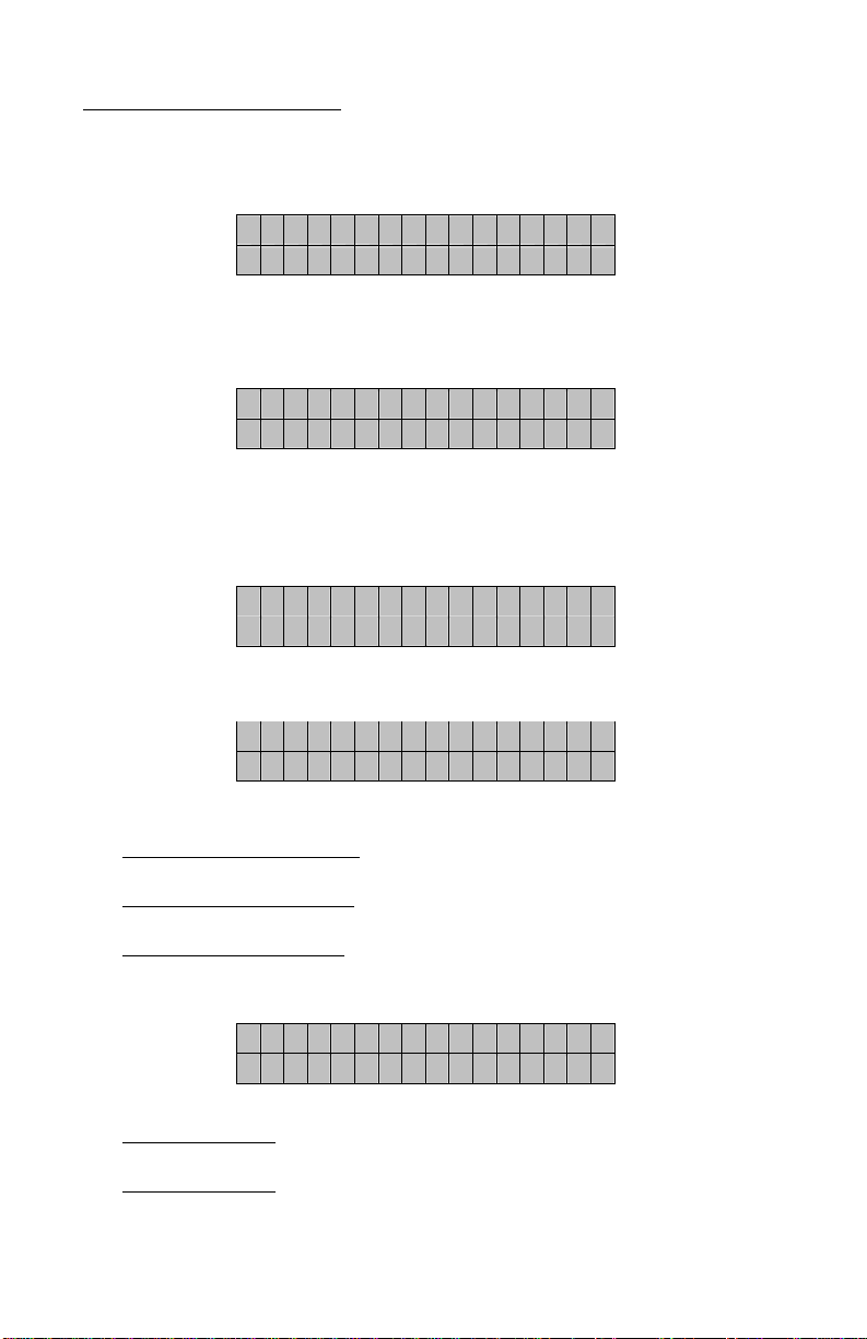
R u n T i m e : R u n n i n g
0 y 0 d 2 h 2 8 m
Run Time Screen: Displays the status of the MotorSaver®and the total motor run time.
MotorSaver®Status: The following codes may be displayed:
§Running - The MotorSaver’s contacts are energized and the motor is running.
§MotorOff - The MotorSaver’s contacts are energized, but the motor is not
running.
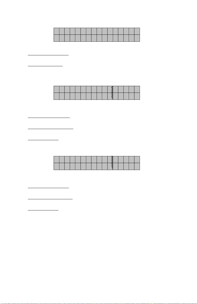
§Pend Flt - A fault is detected. The trip delay timer is incrementing—the
MotorSaver®will trip when the trip delay setpoint is met. If the fault
condition ends, the pending fault will clear and the trip delay timer
will decrement back down to zero.
§Tripped - The MotorSaver®tripped due to a fault condition. The fault can be
viewed on the following screen. Fault #1 is the last fault (most
recent), fault #2 the second to last fault, and so on.
§Restart - The MotorSaver®is timing through the restart delay on power-up.
This is a normal function.
OR
The MotorSaver®tripped due to a fault condition. The condition has
cleared and the MotorSaver®is timing through the restart delay
before energizing the contacts.
OR
The motor has been turned off and the MotorSaver®is timing
though the set restart delay to prevent rapid cycling.
§Manual - The MotorSaver®tripped, the fault condition has cleared, but the
restart delay is set to MAN (manual). Turn the restart delay out of
the manual position to allow the motor to restart.
OR
The MotorSaver®is set to MAN (manual) at power-up. Turn the
restart delay setting out of MAN to energize the contacts.
§CFLckOut - The MotorSaver®Model 455 has tripped due to a load-side problem
such as contactor failure, worn or pitted contacts, loose or broken
wires, etc. A manual reset is always required when this fault occurs.
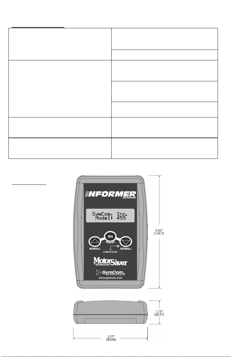
Run Time: The definition of run time is the total length of time a particular MotorSaver®
Model 455 has run a motor—also called “run hours.”
Note: To reset the Model 455’s run hours, first remove power. Make a note of each of
the Model 455’s adjustable settings. Turn all of the setpoint knobs to the
minimum position, i.e., VOLT. ADJ. and RESTART fully counter-clockwise;
UNBALANCE TRIP AND TRIP DELAY fully clockwise. Apply power momentarily,
then remove power again to readjust each setting back to the noted/desired level.
Reapply power.

F l t # 1 : H V
@
0 y 0 d 6 h 4 2 M
F l t # 1 : V U B = 4 %
A v g V o l t = 4 2 6 V
Fault Screens: There are three fault screens for each of the last 20 faults.
Fault: The first fault screen displays the type of fault and the time it occurred in year,
day, hour, and minute corresponding to the total motor run time. Fault codes include:
•HV – High Voltage
•LV – Low Voltage
•VUB – Voltage Unbalance
•SP – Single Phase
•RP – Reverse Phase
•CF – Contactor Failure
Fault Unbalance and Average Voltage: The second fault screen displays the line voltage
unbalance and average line voltage at the time of the fault.
Fault Line Voltage: The third fault screen displays each line-to-line voltage at the time of
the fault.
Motor Start Screen: There are 32 possible motor start screens. The Informer MS will display
the time of each of the last 32 motor starts with #1 being the earliest start and #32 being the
latest (most recent) start.
Motor Start: The motor start screen displays the time of each motor start in year, day,
hour, and minute corresponding to the total motor run time.
F l t # 1 : V A C = 4 2 6
V B C = 4 1 4 V C A = 4 4 4
M o t o r S t a r t 1
@
3 1 y 3 3 5 d 2 0 h 1 4 m

TROUBLESHOOTING
Battery Polarity Reversed – Verify the + and -
terminals on the battery match the markings
inside the battery compartment.
The Informer MS does not activate when the
ON button is pressed.
Low Battery – Replace the battery.
Weak Signal – Ensure the Informer MS is
aimed directly at the MotorSaver’s IR LED and
is within the operating distance (See Figure 1).
MotorSaver®Not Transmitting – Verify the
MotorSaver®is energized and the green RUN
light is illuminated.
The COMM STATUS light is off and all display
values remain at zero.
Sunlight – Make sure the sun is not shining
directly onto the Informer MS’s infrared receiver.
The COMM STATUS light is blinking and/or
the display values fluctuate radically.
Weak Signal – Ensure the Informer MS is
aimed directly at the MotorSaver’s IR LED and
is within the operating distance (see Figure 1).
The Informer MS displays values even after
communication is lost.
This Is Normal – The Informer MS holds the
last values it received before communication
was lost.
DIMENSIONS

INFORMER MS SPECIFICATIONS
Power
Input 9 Volts dc (requires one
9-volt alkaline battery)
Consumption 0.25 Watt (max.)
Automatic shut-off 2 min.
Communication
Signal Infrared
Range 1-8 ft.
Data Update 4 seconds
Accuracy
Voltage ±2%
Resolution
Voltage 1.0VAC
Voltage Unbalance 1%
Time 1 minute
Trip Delay 2 seconds
Restart Delay 2 seconds
Display (Liquid Crystal)
Size 2 rows x 16 characters
Keypad (Three 0.5” buttons)
Mechanical Life 50,000 actuations
Overlay Material Polyester
Enclosure
Dimensions 5.50” H x 3.6” W x 1.125” D
Weight 6 oz. (w/o battery)
Material Black polycarbonate
Operating Temperature 0° to 60°C
MODEL 455 COMPATIBILITY
In March 2006, an infrared LED
transmitter was added to all
MotorSaver®Model 455 units to
communicate with the Informer MS. If
your model 455 includes three small
holes to the left of the MotorSaver®
logo labeled “IR LINK,” it is
compatible with the Informer MS.
An auxiliary kit (3 ft. flexible light pipe)
attaches to the IR LINK holes on the
Model 455 and to the outside of the
panel to allow communication without opening the panel door.
The part number for this infrared kit is Informer MS IR Kit and is available at a nominal cost.
SymCom warrants its microcontroller-based products against defects in material or workmanship
for a period of five (5) years from the date of manufacture. All other products manufactured by
SymCom shall be warranted against defects in material and workmanship for a period of two (2)
years from the date of manufacture. For complete information on warranty, liability, terms, returns,
and cancellations, please refer to the SymCom Terms and Conditions of Sale document.
L1 L2 L3
190-480 VAC, 3Ø, 50/60 HZ
MODEL455
OVER
VOLT. PHASING
FAULT UNDER
VOLT.
PILOT DUTYRATING
480VAAT 240 VAC
RUN
VOLT. ADJ .
(VAC)
208
416 220
440
200
400 230
460
190
380 240
480
UNBALANCE
TRIP (NEM A %)
8
2
M1 M2 M3
SymCom. Inc.
300
100
2
MAN
RES TAR T
(SEC)
30
2
15
TRIP
DEL AY
(SEC)
IND. CONT. EQ.
LISTED
784X
Table of contents
Other SymCom Diagnostic Equipment manuals
Popular Diagnostic Equipment manuals by other brands

Volkswagen
Volkswagen VAS 5581/4 operating manual

Gossen MetraWatt
Gossen MetraWatt PROFITEST H+E BASE operating instructions

RIDGID
RIDGID NaviTrack Scout operating instructions

TECNOMOTOR
TECNOMOTOR RASTHER III quick guide

Stereo Optical
Stereo Optical OPTEC PLUS user manual

Hofmann Megaplan
Hofmann Megaplan megaline SSENCE Series installation manual