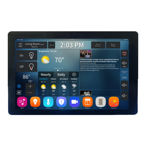
Symetrix T-10 Glass User manual

• The lightning ash with arrowhead
symbol within an equilateral triangle is
intended to alert the user of the presence
of uninsulated “dangerous voltage”
within the product’s enclosure that may
be of sufcient magnitude to constitute
a risk of electric shock to persons. The
exclamation point within an equilateral
triangle is intended to alert the user of
the presence of important operating and
maintenance (servicing) instructions in the
literature accompanying the product (i.e.
this Quick Start Guide).
• CAUTION: To prevent electric shock,
do not use the polarized plug supplied
with the device with any extension cord,
receptacle, or other outlet unless the
prongs can be fully inserted.
• User Serviceable Parts: There are no
user serviceable parts inside this Symetrix
product. In case of failure, customers
inside the U.S. should refer all servicing to
the Symetrix factory. Customers outside
the U.S. should refer all servicing to an
authorized Symetrix distributor. Distributor
contact information is available online at:
http://www.symetrix.co.
AVIS:
NE PAS OUVRIR
Il ne se trouve a l’interieur aucune piece pourvant entre reparée l’usager.
SEE OWNERS MANUAL. VOIR CAHIER D’INSTRUCTIONS.
S’adresser a un reparateur compétent.
RISQUE DE CHOC ELECTRIQUE
No user serviceable parts inside. Refer servicing to qualified service personnel.
CAUTION
WARNING:
TO REDUCE THE RISK OF FIRE OR
ELECTRIC SHOCK DO NOT EXPOSE
THIS EQUIPMENT TO RAIN OR MOISTURE
DO NOT OPEN
RISK OF ELECTRIC SHOCK
Important Safety Instructions
1. Read these instructions.
2. Keep these instructions.
3. Heed all warnings.
4. Follow all instructions.
5. Do not use this apparatus near water.
This apparatus shall not be exposed
to dripping or splashing and no objects
lled with liquids, such as vases, shall be
placed on the apparatus.
6. Clean only with dry cloth.
7. Do not block any ventilation openings.
Install only in accordance with the
manufacturer’s instructions.
8. Do not install near any heat sources such
as radiators, heat registers, stoves, or
other apparatus (including ampliers) that
produce heat.
9. Ensure proper ESD control and grounding
when handling exposed I/O terminals.
10. Protect the cord from being walked on or
pinched particularly at plugs, convenience
receptacles, and the point where they exit
from the apparatus.
11. Only use attachments/accessories
specied by the manufacturer.
12. Use only with the cart, stand, tripod,
bracket, or table specied by the
manufacturer, or sold with the apparatus.
When a cart is used, use caution when
moving the cart/apparatus combination to
avoid injury from tip-over.
13. Unplug this apparatus
during lightning storms
or when unused for long
periods of time.
14. Unplug this apparatus during lightning
storms or when unused for long periods
of time.
15. Refer all servicing to qualied service
personnel. Servicing is required when
the apparatus has been damaged in any
way, such as power-supply cord or plug
cord is damaged, liquid has been spilled
or objects have fallen into the apparatus,
the apparatus has been exposed to rain
or moisture, does not operate normally,
or has been dropped.
Note: This equipment has been tested and found to comply with the
limits for a Class B digital device, pursuant to part 15 of the FCC
Rules. These limits are designed to provide reasonable protection
against harmful interference in a residential installation. This equipment
generates, uses and can radiate radio frequency energy and, if not
installed and used in accordance with the instructions, may cause
harmful interference to radio communications. However, there is no
guarantee that interference will not occur in a particular installation. If
this equipment does cause harmful interference to radio or television
reception, which can be determined by turning the equipment off and
on, the user is encouraged to try to correct the interference by one or
more of the following measures:
• Reorient or relocate the receiving antenna.
• Increase the separation between the equipment and receiver.
• Connect the equipment into an outlet on a circuit different from that to
which the receiver is connected.
• Consult the dealer or an experienced radio/TV technician for help.
Modifications not expressly approved by the manufacturer could void
the user’s authority to operate the equipment under FCC rules.
Cet appariel numerique de la classe B respecte toutes les Exigences du
Reglement sur le materiel brouilleur du Canada.
1 of 6
QUICK START GUIDE: T-10 Glass Touchscreen
What Ships in the Box
• T-10 Glass touchscreen
• Universal flush mount wall bracket
• Two zinc-plated steel M3.5x0.6x25mm
Phillips head machine screws
• Four zinc-plated steel 1.25” 6-32 Phillips
head machine screws
• This Quick Start Guide
What You Need to Provide
Windows PC with 1 GHz or higher
processor and:
• Windows 10 or higher
• 250 MB free storage space
• 1280x1024 graphics capability
• 16-bit or higher colors
• Internet connection
• 8 GB or more of RAM as required by your
operating system
• Network (Ethernet) interface
• CAT5 cable or an existing Ethernet network
Getting Help
Composer™, the Windows software that
configures the T-10 Glass touchscreen
hardware, includes a help file which acts
as a complete User’s Guide for both hardware
and software. If you have questions beyond
the scope of this Quick Start Guide, contact
our Technical Support Group in the
following ways:
Tel: +1.425.778.7728 ext. 5
6:00 am to 5:00 pm PST
Monday through Friday
Web: https://www.symetrix.co
Email:
Forum: https://forum.symetrix.co
www.symetrix.co | +1.425.778.7728
PN 53-0088 Rev A 05/22

2 of 6
QUICK START GUIDE: T-10 Glass Touchscreen
Wall Mount Installation Instructions
www.symetrix.co | +1.425.778.7728
PN 53-0088 Rev A 05/22
Optional, if portrait mounting the touchscreen, remove the
4 screws on the T-10 Glass rear panel support bracket.
Rotate the support bracket 90 degrees so the RJ-45
points down in the desired orientation and ensure the
indicated notch in the support bracket is pointed down.
Take care not to disconnect or strain the internal cables
when rotating the bracket. Reattach with the same
screws. The same steps can be performed to convert a
portrait screen back to landscape.
Screw the universal ush mount wall bracket into the wall
mounted back box using the appropriate screws for US or
EU boxes as shown below.
1.
Connect the CAT5/6 cable to the T-10 Glass touchscreen.
3.2.
Attach the T-10 Glass touchscreen onto the universal
ush mount wall bracket by rst hooking the snaps on
the touchscreen rear panel onto the top tabs of the
wall bracket. Then press the bottom of the touchscreen
enclosure to snap the bottom hooks onto the tabs of the
wall bracket.
4.

3 of 5
QUICK START GUIDE: T-10 Glass Touchscreen
www.symetrix.co | +1.425.778.7728
PN 53-0088 Rev A 05/22
Tabletop Stand Installation Instructions
The instructions below describe how to mount the T-10 to the
optional tabletop stand (purchased separately).
Attach the four (4) included non-skid pads to the under-
side of either the upper or lower table mount bracket,
depending on which surface will be rested upon.
2.
Attach the universal ush mount wall bracket to the
upper and lower table mount stand sections using the
eight (8) included 6-32 x ¼” screws, as shown in the
image on the left.
1.
5. To remove the T-10 Glass from the universal wall
mount bracket, insert a pry-tool (e.g. at head
screwdriver) between the universal wall mount
bracket and the support bracket. Gently twist/rotate
the tool from one side to the other to disengage the
tabs on support bracket from the anges on the wall
mount bracket.

4 of 6
QUICK START GUIDE: T-10 Glass Touchscreen
Software Installation
ComposerTM is the software that provides real-time set-up
and control of the T-10 Glass touchscreen from a
Windows PC environment.
Use the following procedure to install ComposerTM on
your computer
1. Download the Composer™ software installer from the
Symetrix web site (https://www.symetrix.co).
2. Double-click on the downloaded le and follow the on-
screen directions to install.
After installing the software, refer to the Help File for full
connection and conguration information.
Network Setup
About DHCP
T-10 Glass touchscreen boots with DHCP enabled by default.
This means that as soon as you connect it to a network, it will
look for a DHCP server in order to obtain an IP address. If a
DHCP server is present, T-10 Glass touchscreen will obtain an
IP address from it. This process may take several minutes. With
your PC attached to the same network, and thus getting its IP
address from the same DHCP server, all will be ready to go.
If your network does not have a DHCP server, T-10 Glass
touchscreen will not be able to obtain an IP address. While
waiting, T-10 Glass touchscreen will default to a private IP
address in the range of 169.254.x.x where x.x is the last four
alphanumeric characters of T-10 Glass touchscreen’s MAC
address (MAC address hex value is converted to decimal for IP
address). T-10 Glass touchscreen’s MAC address can be found
on a sticker on the bottom of the hardware.
When there is no DHCP server present to assign IP addresses
to the T-10 Glass touchscreen, or your PC, you may need to
congure your PC with a static IP in the range of 169.254.x.x
with a Subnet Mask of 255.255.0.0 in order to communicate
with T-10 Glass touchscreen in a direct connect mode.
However, if your PC is using the default network settings, it
should also have automatically self-assigned a similar private IP
address in the range of 169.254.x.x, and if this is the case, you
should be able to connect to T-10 Glass touchscreen directly.
Even if the PC’s default settings have been changed, T-10
Glass touchscreen will try to establish communications by
setting up appropriate routing table entries to reach devices with
169.254.x.x addresses.
Connecting to T-10 Glass from a host computer
on the same LAN
The T-10 Glass and the host computer require the following
3 items:
1. IP Address - The unique address of a node on a network.
2. Subnet Mask - Conguration that denes which IP addresses
are included in a particular subnet.
3. Default Gateway (optional) - The IP address of a device that
routes trafc from one subnet to another. (This is only needed
when the PC and T-10 Glass are on different subnets).
Connect the CAT5/6 cable to the T-10 Glass touchscreen.
3.
Align and gently press the T-10 unit onto the wall mount
bracket by rst hooking the snaps on the touchscreen rear
panel onto the top tabs of the wall bracket. Then press the
bottom of the touchscreen enclosure to snap the bottom
hooks onto the tabs of the wall bracket. Ensure the device
is seated and ush to the tabletop stand.
4.
To remove the T-10 Glass from the universal wall mount
bracket, insert a pry-tool (e.g. at head screwdriver)
between the universal wall mount bracket and the support
bracket. Gently twist/rotate the tool from one side to the
other to disengage the tabs on support bracket from the
anges on the wall mount bracket.
5.
www.symetrix.co | +1.425.778.7728
PN 53-0088 Rev A 05/22

5 of 5
QUICK START GUIDE: T-10 Glass Touchscreen
www.symetrix.co | +1.425.778.7728
PN 53-0088 Rev A 05/22
- or -
- or -
Conguring IP Parameters
Locating Hardware
Discovery of, and connection to, T-10 Glass
touchscreen hardware is done with the Locate
Hardware dialog found under the Hardware
menu or by clicking the Locate Hardware icon
in the tool bar or on a particular T-10 Glass
touchscreen unit itself.
IP Conguration with ComposerTM
The Locate Hardware dialog will scan the network and list
available units. Select the T-10 Glass touchscreen unit you
wish to assign an IP address to and click the Properties
button. If you wish to assign a T-10 Glass touchscreen a
static IP address, select “Use the following IP address”
and enter the appropriate IP address, Subnet mask and
Gateway. Click OK when nished. Now, back in the Locate
Hardware dialog, ensure the T-10 Glass touchscreen
device is selected and click “Select Hardware Unit” to use
this T-10 Glass touchscreen hardware in your Site File.
Close the Locate Hardware dialog.
Reset Switch
To be used under the supervision of technical support, it has
the ability to reset the T-10 Glass touchscreen’s network
configuration and completely reset the unit to factory defaults.
Locate the reset switch through the vents on the bottom side
of the T-10 Glass rear cover.
1. Short press and release: Reboots the unit.
2. Long press and hold, release when unit reboots:
Resets network configuration, returns to DHCP.
3. Apply power while holding, release after unit boots then
reboots: Factory resets unit.
Declaration of Conformity
We, Symetrix Incorporated, 6408 216th St. SW,
Mountlake Terrace, Washington, USA, declare under our
sole responsibility that the product:
T-10 Glass
to which this declaration relates, is in conformity with the
following standards:
EN 55032
FCC Part 15 (EMC-USA),
EN 301 489-17 V3.2.4:2020-09
The technical construction le is maintained at:
Symetrix, Inc.
6408 216th St. SW
Mountlake Terrace, WA, 98043 USA
The authorized representative located within the European
Community is:
World Marketing Associates
P.O. Box 100
St. Austell, Cornwall, PL26 6YU, U.K.
Date of issue: January 15th, 2019
Place of issue: Mountlake Terrace, Washington, USA
Authorized signature:
Mark Graham, CEO, Symetrix Incorporated.
If you are putting T-10 Glass on an existing network, a network
administrator will be able to provide the above information, or
it may have been provided automatically by a DHCP server.
For security reasons, it is not recommended to put T-10 Glass
directly on the Internet. If you do, a network administrator or your
Internet Service Provider can provide the above information.
If you are on your own private network, directly or indirectly
connected to T-10 Glass, you may allow the device to choose
an automatic IP address or you may choose to assign it a static
IP address. If you are building your own separate network
with static assigned addresses, you may consider using an IP
Address from one of the ”Private-Use” networks noted in RFC-
1918:
1. 172.16.0.0/12 = IP Addresses 172.16.0.1 through
172.31.254.254 and a Subnet Mask of 255.240.0.0
2. 192.168.0.0/16 = IP Addresses 192.168.0.1 through
192.168.254.254 and a Subnet Mask of 255.255.0.0
3. 10.0.0.0/8 = IP Addresses 10.0.0.1 through 10.254.254.254
and a Subnet Mask of 255.255.0.0

6 of 5
QUICK START GUIDE: T-10 Glass Touchscreen
The Symetrix Limited Warranty
By using Symetrix products, the Buyer agrees to be bound by the terms of
this Symetrix Limited Warranty. Buyers should not use Symetrix products
until the terms of this warranty have been read.
What is Covered by this Warranty:
Symetrix, Inc. expressly warrants that the product will be free from defects
in material and workmanship for ve (5) years from the date the product
is shipped from the Symetrix factory. Symetrix’s obligations under this
warranty will be limited to repairing, replacing, or partially crediting original
purchase price at Symetrix’s option, the part or parts of the product which
prove defective in material or workmanship within the warranty period
provided that the Buyer gives Symetrix prompt notice of any defect or failure
and satisfactory proof thereof. Symetrix may, at its option, require proof of
the original date of purchase (copy of original authorized Symetrix Dealer’s
or Distributor’s invoice). Final determination of warranty coverage lies
solely with Symetrix. This Symetrix product is designed and manufactured
for use in professional audio systems and is not intended for other usage.
With respect to products purchased by consumers for personal, family, or
household use, Symetrix expressly disclaims all implied warranties,
including, but not limited to, warranties of merchantability and tness
for a particular purpose. This limited warranty, with all terms, conditions
and disclaimers set forth herein, shall extend to the original purchaser and
anyone who purchases the product within the specied warranty period
from an authorized Symetrix Dealer or Distributor. This limited warranty
gives the Buyer certain rights. The Buyer may have additional rights
provided by applicable law.
What is not Covered by this Warranty:
This warranty does not apply to any non-Symetrix branded hardware
products or any software even if packaged or sold with Symetrix Products.
Symetrix does not authorize any third party, including any dealer or
sales representative, to assume any liability or make any additional
warranties or representations regarding this product information on
behalf of Symetrix.
This warranty also does not apply to the following:
1.Damage caused by improper use, care, or maintenance or failure to
follow the instructions contained in the Quick Start Guide or Help File.
2. Symetrix product that has been modied. Symetrix will not perform
repairs on modied units.
3.Symetrix software. Some Symetrix products contain embedded software
or apps and may also be accompanied by control software intended to
be run on a personal computer.
4. Damage caused by accident, abuse, misuse, exposure to liquids, re,
earthquake, acts of God, or other external causes.
5.Damage caused by improper or unauthorized repair of a unit.
Only Symetrix technicians and Symetrix international distributors are
authorized to repair Symetrix products.
6.Cosmetic damage, including but not limited to scratches and dents,
unless failure has occurred due to a defect in materials or workmanship
within the warranty period.
7.Conditions caused by normal wear and tear or otherwise due to the
normal aging of Symetrix products.
8.Damage caused by use with another product.
9.Product on which any serial number has been removed,
altered or defaced.
10. Product that isn’t sold by an authorized Symetrix Dealer or Distributor.
Buyer Responsibilities:
Symetrix recommends the Buyer make backup copies of site les before
having a unit serviced. During service it is possible that the site le will be
erased. In such an event, Symetrix is not responsible for the loss or the
time it takes to reprogram the site le.
Legal Disclaimers and Exclusion of other
Warranties:
The foregoing warranties are in lieu of all other warranties, whether oral,
written, express, implied or statutory. Symetrix, Inc. expressly disclaims
any IMPLIED warranties, including tness for a particular purpose or
merchantability. Symetrix’s warranty obligation and Buyer’s remedies
hereunder are SOLELY and exclusively as stated herein.
Limitation of Liability:
The total liability of Symetrix on any claim, whether in contract, tort
(including negligence) or otherwise arising out of, connected with,
or resulting from the manufacture, sale, delivery, resale, repair,
replacement or use of any product will not exceed the retail price
of the product or any part thereof which gives rise to the claim. In
no event will Symetrix be liable for any incidental or consequential
damages including but not limited to damage for loss of revenue, cost
of capital, claims of Buyers for service interruptions or failure to supply,
and costs and expenses incurred in connection with labor, overhead,
transportation, installation or removal of products, substitute facilities or
supply houses.
Servicing a Symetrix Product:
The remedies set forth herein shall be the Buyer’s sole and exclusive
remedies with respect to any defective product. No repair or
replacement of any product or part thereof will extend the applicable
warranty period for the entire product. The specic warranty for any
repair will extend for a period of 90 days following the repair or the
remainder of the warranty period for the product, whichever is longer.
Residents of the United States may contact the Symetrix Technical
Support Department for a Return Authorization (RA) number and
additional in-warranty or out-of-warranty repair information.
If a Symetrix product requires repair services outside of the United
States please contact the local Symetrix dealer or distributor for
instructions on how to obtain service.
Products may be returned by Buyer only after a Return
Authorization number (RA) has been obtained from Symetrix.
Buyer will prepay all freight charges to return the product to the
Symetrix factory. Symetrix reserves the right to inspect any products
which may be the subject of any warranty claim before repair or
replacement is carried out. Products repaired under warranty will be
returned freight prepaid via commercial carrier by Symetrix, to any
location within the continental United States. Outside the continental
United States, products will be returned freight collect.
www.symetrix.co | +1.425.778.7728
PN 53-0088 Rev A 05/22
Table of contents
Other Symetrix Touchscreen manuals