Wiggly-Amps Engage User manual

Wiggly-Amps Ltd
40, Market Place
North Walsham
Norfolk
NR28 BT
Web: www.wiggly-amps.com
e-mail: info@wiggly-amps.com
Telephone: +44 (0)1263 834648
Engage Touchscreen
Installation instructions
27/11/13 JW Initial release for compact screens

Overview
These instructions are intended to allow anyone with a basic level of DIY skills to install the Engage
Touchscreen system in a safe and secure fashion. If you are unsure of anything or just need to
confirm your understanding, please contact Wiggly-Amps and we'll be pleased to help.
Specification
Dimensions: 440 x 373 x 75
Weight: 7.75 Kg
Power: 35W
Choosing a location
There are a number of things to consider when siting your screen, some obvious and some less so.
Think first about the flow of people around your surgery:
•Will it be easily seen by patients on arrival?
•Is it going to be obscured by people queuing at reception?
•Is a patient likely to be easily overlooked when using the system?
You should also consider the physical aspects of the installation:
•How are the power and network cables going to be routed?
•Is it going to be in direct sunlight at any time of year?
•Is it clear of any direct heat source such as a radiator or heater?
•Is it going to have 50mm clear at the top and bottom to allow airflow for cooling?
Installing the Screen
There are three methods that you can use to mount your system:
•Desktop
•VESA mount
•Direct to wall
Detailed instructions are available in the Annexes to this document.
Setting up the software
The last step is to configure your screen to talk to your Clinical system. Once the screen is powered
up and connected to your network, please give us a call on 01263 834648 and we'll finish off the
setup process and give you a run through of the system, and it's features. This involves the
installation of a small piece of software on one of your workstations (Ideally reception) to allow you
to control the screen remotely.

ANNEX A – Desktop Mount
The optional Desktop mounting bracket lets you place the screen on a table or low counter top.
Fitting the mount is a simple process, requiring a medium sized cross-head screwdriver.
Start by placing the screen face down on the table, you may want
to place a towel or similar under it to protect the display and the
work surface.
Next, unscrew the 4 screw bolts highlighted opposite and put
them to one side.
Place the mount on the screen as shown, then replace all 4
screw bolts loosely with your fingers (Don't forget the washers on
the top two bolts)
Tighten the BOTTOM pair of bolts first.
Finally, tighten the top two screw bolts. You may need to slightly flex
the mount to get the washers to sit flush.
Your screen is now ready for putting in position.

ANNEX - VESA mount
The optional VESA mounting bracket allows
you to use any commercial VESA100 mounting
system, such as a pedestal or wall arm mount.
If your screen does not already have the mount
fitted, it's a simple process, requiring a medium
sized cross-head screwdriver.
As you can see in the picture opposite, the
VESA mount comes along with a fan guard.
This is to prevent patients accidentally placing
their fingers in the fan if they “Hold” the screen
whilst using it. For direct wall and desktop
mounted screens, this isn't an issue as the fan
is inaccessible.
Start by placing the screen face down on the table, you
may want to place a towel or similar under it to protect the
display and the work surface.
Next, unscrew the 4 screw bolts highlighted opposite and
put them to one side.
Take the VESA mounting bracket and peel off the
protective cover from the anti-vibration foam strip at
the top.

Place the mount on the back of the screen. If your
chosen mounting system allows you to route the
cables through the middle, now is the time to run
the power and network leads through the hole in the
middle.
Next, replace all 4 screw bolts loosely with your
fingers (Don't forget the washers on the top two
bolts).
Tighten the BOTTOM pair of bolts first, then the top
pair.
Finally, we fit the fan guard. Remove TWO screws
only from diagonally opposite corners, then re-fit
them with the fan guard as shown.
Please don't be tempted to unscrew all 4 screws, as
the fan will fall into the case!
Your screen is now ready for attaching to your
chosen mounting system.

ANNEX C - Wall Mount
The screen is designed to attach directly to a suitable wall. It is possible to
route the cables from behind and keep them completely hidden, making for a
very tidy installation. You will need a medium sized cross-head screwdriver
and whatever tools are required to screw in the 5 fixings the screen requires.
We do not supply fixings with the screens, as it very much depends on the
construction of the wall you're attaching it to.
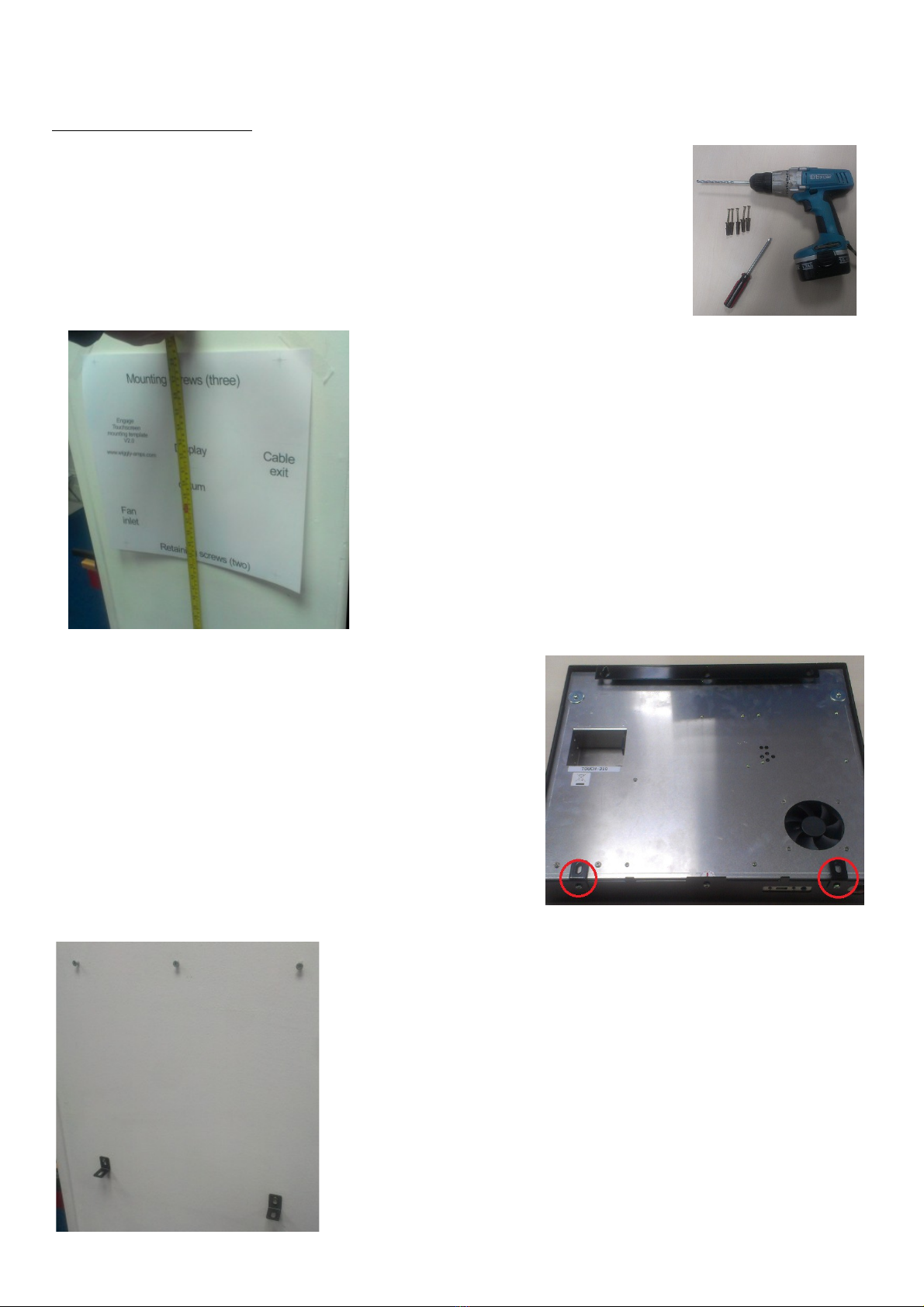
Start by offering up the template to your chosen location
and affixing it to the wall with a few pieces of tape at the
required height – don't forget to use a spirit level! We
suggest 130cm from floor to the “Display datum” cross in
the middle of the template.
Next, using a sharp object, mark the wall for the positions
of the 5 screws, 3 at the top and 2 at the bottom.
If you are planning an installation with cables coming from
the rear, note that the template includes the positions of
the Cable exit area and the fan to assist with the wiring.
Place the screen face down on the table, you may want to
place a towel or similar under it to protect the display and
the work surface.
Remove the two screw bolts at the foot of the screen that
are holding the screen retaining mounts.
Fit the screws - drive the top ones in first. The exact depth will
depend on the fixings you use,but aim to leave 3-4mm of shaft
exposed to allow the screen case to hang off them.
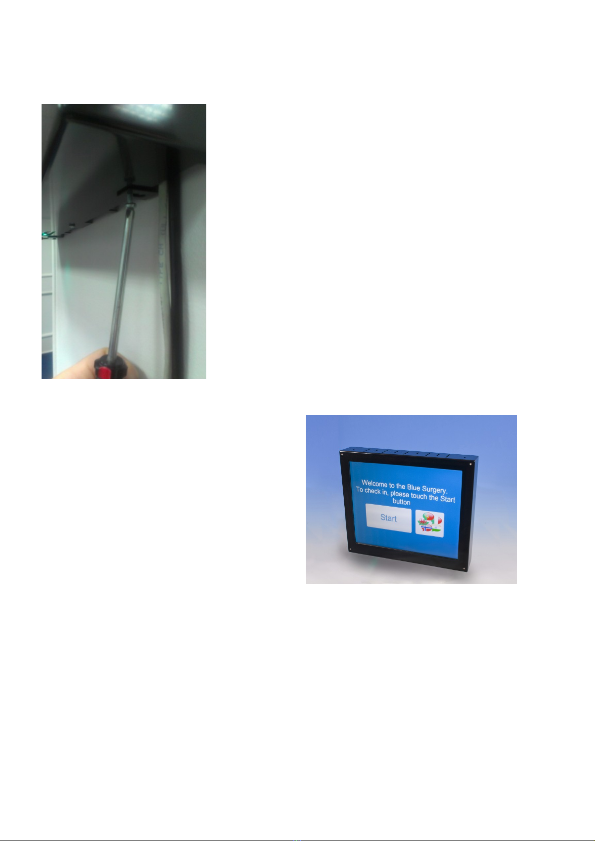
Next, fit the two screen retaining mounts to the bottom pair of
holes. Don't over-tighten these, you should aim for them to be
tight against the wall, but still be able to rotate them with light to
moderate pressure. Whilst you can mount the screen without
these, we would strongly advise against it as they are there to
stop people lifting the screen off the wall.

Now it's time to hang the screen. As a default, you can either
have the wiring come from behind or route it through the vent
slots at the bottom of the unit (as shown opposite). If you want to
have top-entry, there are a pair of press-out sections of the case
that can be removed as required by wiggling with a pair of pliers.
Offer up the screen to the screws – the centre, long slot at the top
of the case is in line with the middle of the three hanging screws
to assist your aim. Once the screen is flush to the wall, slowly
lower it so that it is hanging on the screws. You should find the
bottom of the case is lightly resting on the two screen retaining
mounts.
When you are happy, replace the screw bolts. Make sure the
screen is flush against the wall before finally tightening them.
Your screen is now ready for use.
Table of contents