Symtech BCA4 Use and care manual

VISUAL
HEADLAMP ALIGNMENT
SYSTEM
ASSEMBLY
OPERATION
CALIBRATION
524 S.E. Transport Drive
Lees Summit, MO 64081
888-884-8182
816-525-9263 FAX: 816-525-9283
www.symtechcorp.net
Safety by Design
System has not been
certified for vehicle
inspection programs
REV: 8/03/12

2

3
INDEX
1. GENERAL Pg. 3
1.1 “BCA 4 ISOCOLOR ” INTRODUCTION
1.2 SYSTEM COMPONENTS
1.3 LASER WARNING
1.4 WARNING, EXPOSURE TO DIRECT SUNLIGHT
2. ASSEMBLY Pg. 4
2.1 BASE / WHEEL ATTACHMENT
2.2 MAST / GLIDE PLATE / ROTATIONAL MAST MOUNT
2.3 OPTICAL ALIGNMENT HEAD
2.4 SIGHTING UNIT
2.5 SIGHTING UNIT CALIBRATION
2.6 FLOOR SLOPE LASER
3. OPERATION Pg. 6
3.1 ALIGNMENT BAY(s) PREPARATION
3.2 FLOOR SLOPE MEASUREMENT
3.3 VEHICLE PREPARATION, Prior to Alignment
4. HEADLAMP ALIGNMENT PG. 7
4.1 ALIGNMENT of OPTICAL HEAD TO VEHICLE
4.2 CENTERING on the HEADLAMP
4.3 SELECTING HEADLAMP PATTERN
4.4 ALIGNMENT of HEADLAMP PROCEDURE
5. LASER CALIBRATION / MAINTENANCE Pg. 8
5.1 LASER CALIBRATION
5.2 MAINTENANCE
6. FREQUENTLY ASKED QUESTIONS Pg. 9
WARRANTY Pg. 10
CUSTOMER SERVICE
888-884-8182

4
1. GENERAL
1.1 INTRODUCTION
The Model “BCA 4 ISOCOLOR” Visual Headlamp Alignment System is an economical optical alignment
tool that functions under the same principle for accuracy and dependability of an aiming screen, with the
added benefit of Symtech Corporation’s “BCA 4 ISOColor” technology, without the excessive use of
valuable shop space and the confusion of vertical and horizontal lamp placement. System design and
operation has been engineered with the technician in mind. The “BCA 4”” features ISOColor technology
that facilitates headlamp alignment, with profitability and customer satisfaction as the end result.
The Model “BCA 4 ISOColor” is designed, manufactured and serviced by Symtech Corporation, Lees
Summit, Missouri, the industry leader in headlamp alignment technology to the service and body repair
industries, the architect of the Model “LCA 2 EZ” Visual, “SCA 1 ISOColor” Visual, “CVA 3 EZ
ISOColor” Visual and the ”HBA 5” Electronic Headlamp Alignment systems along with the “AIM 200”
Headlamp Intensity meter.
System has not been certified for inspection programs.
We are confident that the “BCA 4 ISOColor” will provide you with years of exceptional service. Thank
you for selecting a Symtech “Safety by Design” product to address your headlamp alignment needs.
1.2 SYSTEM COMPONENTS
1.3 LASER WARNING
AVOID LOOKING DIRECTLY INTO LASER
LIGHT –POSSIBLE EYE INJURY CAN
OCCUR.
1.4 WARNING, EXPOSURE TO DIRECT SUNLIGHT
DO NOT PLACE OR POSITION “BCA 4” SO THAT DIRECT SUNLIGHT ENTERS
FRONT LENS. DOING SO WILL CAUSE DAMAGE TO ISOColor SCREEN AND
VOID WARRANTY. Front lens acts like an enlarged magnifying glass which will
concentrate direct sunlight into a destructive high intensity beam on the aim screen.
SIGHTING UNIT
Small Parts Package
2 Large Nylon Washers
2 5/16” Nylon Washers
2¼” x 1/8” (WHITE)Nylon
Spacers
2 ¼” x 3/16” (BLACK)Nylon
Spacers
2 5/16” Self-Locking Nuts
41/4” x 20 Machine Screws
4 ¼” x 20 Machine Screws
1 3/8” Self Locking Nut
1 3/8” Flat Washer
DANGER
LASER RADIATION
AVOID DIRECT EYE EXPOSURE
PEAK POWER < 5mW
WAVELENGTH 400-700nm
00-710nm
CLASS IIIA LASER PRODUCT
Large Parts Package
2 5/16” x 5 ½” Carriage Bolts
1 Floor Slope Handle
2 Wheels
1 Wheel w/Floor Slope
Eccentric
1 3” Rotational Bearing
BASE & WHEELS
GLIDE PLATE
MAST
Exploded
View
Rotational
Mount
FLOOR SLOPE
LASER
OPTICAL HEAD
FLOOR SLOPE
AXEL
OPTIONAL
DUST COVER
P/N: 040160000

5
2. ASSEMBLY
Inspect all components of the :BCA 4 ISOColor system to assure that no damage has occurred during shipment, compare
contents of package with that of the exploded view to make sure that no component has been inadvertently left out of
packaging. If a component is missing, contact our customer service department at 888-884-8182 for an immediate
replacement.
2.1 BASE / WHEEL ATTACHMENT
Place base of system on floor, or table with channel facing
downward.
Insert a 5/16” x 5 1/2” carriage bolt into each of the holes noted,
making sure that the square carriage bolt head seats securely into the
square hole placement.
Complete wheel assembly by placing in order a large nylon washer,
wheel, small nylon washer and self-locking 5/16” nut on carriage
bolt.
Tighten self-locking nut snug against wheel, but not so tight as to
hinder free wheel movement.
Insert floor slope eccentric and wheel into mounting block on base
(rear wheel). Tighten friction bolt until floor slope eccentric can be
moved, but not loose enough to move by itself.
2.2 MAST / GLIDE PLATE / ROTATIONAL MAST MOUNT
The Mast and Glide Plate are packaged as an assembly.
Place rotation bearing over mast stud and insert rotational mast stud
into base. Secure mast to base with 3/8” flat washer and 3/8” self-
locking nut. Tighten nut securely then back-off 1/8turn, or until
mast rotates freely with minor resistance.
Move glide plate up and down the mast through its full motion, by
depressing handle.
2.3 OPTICAL ALIGNMENT HEAD
Remove optical alignment head from shipping carton.
Inspect for any damage that may have occurred during
shipment i.e. lens, case, etc..
Attach optical alignment head to the mast glide plate by
aligning mounting holes of glide plate with the holes in
the optical head. Insert ¼” x 20 x ¾” phillips machine
screw through glide plate, place a ¼” x 1/8” (WHITE)
nylon spacer on each upper attachment screw, place a ¼”
x 3/16” (BLACK) nylon spacer on each lower attachment
screw and tighten securely.
Remove protective paper covering from viewing window
on top of optical head.
Move optical head through the full range of movement to
assure of smooth operation.
2.4 SIGHTING UNIT
Sighting unit is the “L” bracket assembly enclosed
in the accessories box.
NOTE: Mount sighting unit so that unit is
located directly over the optical head.
Insert the 5/16” x 2.5” phillips head machine screw
with 5/16” nylon washer into the sighting unit.
Tighten
this Bolt
Front of Base
Glide
Plate
Optical
Head
¼” x 1/8”
Nylon Spacers
(WHITE)
¼” x 3/16”
Nylon Spacers
(BLACK)
ROTATIONAL
BEARING
¼” x 20 x ¾”
Phillips Machine Screw

6
Place a thick nylon bushing on the screw and insert
screw through the holes provided at the top of the
mast, place a thick nylon bushing on screw and self-
locking nut.
Tighten to a tension that allows for movement of
sighting unit, but provides sufficient friction to hold
unit in place when unattended.
NOTE: Sighting unit must be calibrated to the optical head prior
to alignment of headlamps.
2.5 SIGHTING UNIT CALIBRATION
Calibration of sighting unit must be performed prior to alignment of
headlamps.
Raise optical head of BCA 4 ISOColor to the approximate center
of mast.
Turn the sighting unit until you can see the front edge of the optical
head while looking through the sighting unit lens. Line on lens
should line up with the front edge of the optical head.
If line does not line up with the front edge of optical head, loosen
the thumbscrews on the lens and move the lens into alignment.
Tighten thumbscrews.
It is important that periodical checking of calibration of the sighting
unit be performed, to assure customer satisfaction.
2.6 FLOOR SLOPE LASER
The floor slope laser assembly is factory calibrated, DO
NOT turn the level adjustment set screw.
The laser is used for floor slope measurement only. Remove
laser after floor slope measurements have been recorded.
Remove floor slope laser from packaging and insert front
fixture placement pin into hole on top and at front of the
rear area of the optical head, also there is an indentation
provided for the height adjustment screw to rest within.
Activate the laser by turning ON/OFF knob clockwise
(CAUTION: Excessive turning may damage laser
ON/OFF mechanism) to assure of functionality, turn off
laser. No further adjustment is required.
NOTE: Should calibration of the laser become necessary in
the future, Refer to “LASER CALIBRATION”.
Calibration, Section 5.1, Pg. 9.
Laser Battery Replacement
Unscrew back of laser and replace batteries with three (3), LR 44
button batteries or equivalent. Reverse process for assembly.
After battery replacement, CALIBRATION COULD BE REQUIRED.
Optical
Head
IN
Calibration
OUT of
Calibration
Adjustment
Thumb Screws
Optical
Head
On / Off
Knob
Level Adjuster
Set Screw
Fixture
Placement Pin
ON/OFF
Knob

7
3. OPERATION PROCEDURES
3.1 PREPARATION, ALIGNMENT BAY(s)
Prior to any headlamp alignment using the BCA 4 ISOColor, the floor slope of the bay, or bays must be
determined, this is done by using the floor slope laser assembly and noting the position of the rear floor slope
wheel.
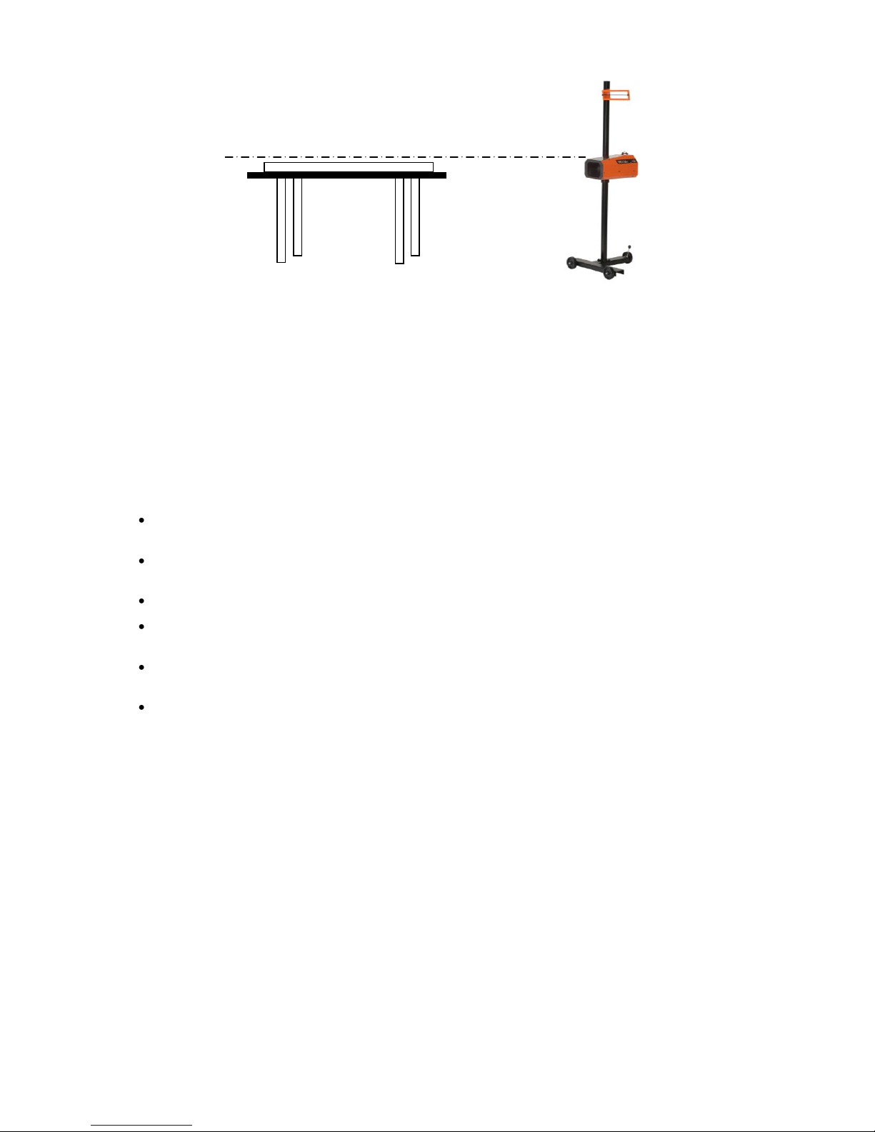
If the correct floor slope of the bay is not adjusted prior to any headlamp alignment, the technician will align
the headlamps in a higher, or lower position than what is correct. The BCA 4 ISOColor must be on the
same plain as the vehicle that is to be aligned, if the vehicle is positioned on a floor that has an upward slope
running from fore to aft of vehicle, then the BCA 4 ISOColor must be adjusted to have the same slope.
3.2 FLOOR SLOPE MEASUREMENT
Tool Required: Tape Measure or Ruler
Move the BCA 4 ISOColor to the service bay to be used for headlamp alignment and place the BCA 4
ISOColor at the front of the vehicle, off to one side. If multiple bays are to be used, procedure for
determining floor slope will need to be performed in each bay and recorded.
Lower the optical head to the bottom of the mast. Adjust optical head by rotating eccentric wheel at rear of
base until level vial registers level. Turn the laser on with the thumbscrew on the front of the laser assembly.
At the center point of the front wheel of the vehicle measure the distance from the floor to the point where the
laser strikes the tape measure, RECORD.
Move to the center point of the rear wheel of vehicle and measure the point where the laser strikes the tape
measure, RECORD.
If the measurements at the front and rear wheels are not equal, the
bay has a slope.
Rotate the floor slope handle on rear wheel until equal
measurements are registered at the front and rear wheels.
NOTE: When rotating eccentric axle on BCA 4 ISOColor, both
measurements will change at front and rear vehicle wheels,
to achieve equal measurements, more than one eccentric
axle adjustment may be required.
Note the number on the floor slope gauge and record that number
along with the bay designate on floor slope sticker provided. Repeat
procedure for other bays and record.
NOTE: After measurements have been taken, remove laser and
store in a secure place
3.3 VEHICLE PREPARATION
Remove ice or mud from under the fenders.
Set the tire inflation to the values recommended by the manufacturer.
See that there is no load in the vehicle unusual to normal driving conditions.
Check vehicle springs for sag or broken leafs.
Check function of any automatic leveling systems and specific manufacturers instructions pertaining to
vehicle preparation for headlamp alignment.
Clean lenses, check for bulb burnout, broken mechanical aiming pads, moisture in lens and proper beam
switching.
MEASURE
MEASURE
FLOOR SLOPE REGISTRY
Bay# Slope Date Bay# Slope Date
_____ _____ ______ _____ _____ ______
_____ _____ ______ _____ _____ ______
_____ _____ ______ _____ _____ ______
_____ _____ ______ _____ _____ ______
_____ _____ ______ _____ _____ ______

8
Stabilize suspension by rocking vehicle sideways.
4. HEADLAMP ALIGNMENT
4.1 ALIGNMENT OF OPTICAL HEAD TO VEHICLE
Place the BCA 4 ISOColor in front of the first headlamp to be
aligned. Once the BCA 4 ISOColor is in place, the lens of the
optical head should be approximately 12 inches (+/- 6 inches) from
the face of the headlamp.
Set the floor slope of the eccentric wheel for the bay in which the
vehicle has been parked.
Rotate the sighting unit so that the front of the vehicle can be seen
through the sighting unit. Locate two (2) common points on or
under the hood to align the line in the sighting unit on.
NOTE: Points can be hood stops, radiator support (s), points
of fender, etc.
While looking through the sighting unit, align the line of the
sighting unit on the two common points by rotating the optical head
of the machine.
The BCA 4 ISOColor is now aligned with the vehicle. Repeat the
alignment process for each lamp.
4.2 CENTERING on the HEADLAMP
Turn headlamps on. Move optical head up, or down to the center of the
headlamp. Position of center of the headlamp is approximate; a 1.5”
allowance is acceptable.
TRICK: A method of determining if position is greater than 1.5” is by
observing the illumination that appears on the front of the optical lens
housing when moving the optical head left/right and up/down.
Position aimer until illumination is of equal proportion around lens.
4.3 SELECTING HEADLAMP PATTERN
Not all headlamps are created alike and different vehicles
may have different design patterns. To be certain of the
lamp pattern, a designate is located on the lamp at the
bottom of the lens. Patterns of lamps that may be aligned
with the BCA 4 ISOColor are;
SAE HIGH BEAM: All high beam lamps. Highest
intensity point is centered on the Horizontal /
Vertical axis.
SAE LOW BEAM: All low beam lamps
manufactured prior to 1999, selective manufacture
after 1999. The high intensity area is located in the
lower right hand quadrant.
FOG/DRIVING LAMPS: All fog/driving lamps the
top of the high intensity area is located 4” down and
centered on the Vertical axis.
SAE LOW BEAM “VOR” (Visual Optical Right):
Low beam lamps manufactured after 1999, some
vehicles. The high intensity area is located in the
lower right hand quadrant and the beam pattern is
aligned by placing the right upper portion of the
beam pattern on the Horizontal axis.
H
V
High Beam
H
V
US Low Beam
V
H
Fog / Driving
Lamp
US Low Beam
VOR
Aim Area
V
H
Common Points

9
SAE LOW BEAM “VOL” (Visual Optical Left):
Low beam lamps manufactured after 1999, some
vehicles. The high intensity area is located in the
lower right hand quadrant and the beam pattern is
aligned by placing the left upper portion of the beam
pattern on the .4 Degree (2.096”) Down Horizontal
axis.
4.4 ALIGNMENT OF HEADLAMP PROCEDURE
1. Locate BCA 4 ISOColor approximately 12 inches
from in front of the lamp to be aligned. Placement can
be 6” to 18” without jeopardizing alignment.
2. Position BCA 4 ISOColor in front of first lamp to be
aligned. Centering of system on headlamp is very
forgiving, as the fresnel lens provides a 1.5” widow
for centering.
3. Align BCA 4 ISOColor to vehicle by sighting
through the sighting unit and rotating optical head
until line in sighting unit intersects the two common
points selected.
4. Headlamps should be switched on to low beam as this
is the primary driving lamp.
a. In compound lamps, where the Low Beam
and the High Beam are in the same lamp,
you only align one pattern, as by law, the
other pattern must be within 1.5” of perfect
alignment.
5. While viewing aim screen, adjust headlamp to position
that appears as graphic illustration of headlamp pattern
selected. The most inner portion of color is the high
intensity zone and this is what you center over the white
designated for the lamp pattern selected.
NOTE: Graphics on aiming screen denote position
of lamp position in inches.
6. Repeat steps for remaining lamps.
6. LASER CALIBRATION / MAINTENANCE
5.1 FLOOR SLOPE LASER CALIBRATION
“LASER IS CALIBRATED AT THE FACTORY PRIOR TO SHIPMENT”
“Calibration Required ONLY if Rear- LASER Adjustment Set Screw has
been tampered with”
Tools Required: Elevated Surface (wheel alignment, frame machine)
Level (carpenters level or other means)
6‘ Straight Edge (board or other means)
5/64” Allen Wrench
H
V
US Low Beam
VOL
.4 Degree Down
(2.096 Inches)
Aim Area
1. Position “BCA 4” in Front of first
lamp to be Aligned.
2. Adjust Floor Slope to Recorded
Bay Setting.
3. Square BCA 4 to Vehicle by
Looking Trough Sighting Unit.
Headlamp Alignment Procedure
4. Aligning Two Common Points with
Line in Sighting Mirror.
5. Select Lamp Beam Type. While
viewing Lamp Patten, Adjust
Lamp to Pictorial Position
6. Move BCA 4 to Next Lamp and
Repeat Steps 3 Through 5.

10
Locate an elevated surface and lay the straight edge on surface facing away from
optical head. Check straight edge for level, shim if necessary.
Move BCA 4 ISOColor to end of straight edge, turn on the laser and adjust
height of optical head so that the mounted laser will shoot down the straight edge.
Adjust the rear floor slope wheel until the level in the optical head is centered. Readjustment of
height of optical block may be necessary.
Adjust the rear height adjustment set screw of the laser assembly (Lock Tight has been installed
on screw at factory, minor pressure should break seal) till laser is viewed at both ends of straight
edge equally.
Laser is now calibrated, installing lock tight or other adhesive to adjustment screw is
recommended.
5.2 MAINTENANCE
The BCA 4 ISOCOLOR will provide years of trouble free operation with minimum maintenance, however,
care should be taken in the day-to-day usage of this service instrument. Following are areas that should be
periodically checked and serviced;
Check wheel axles nuts for tightness, minor lubrication is
recommended.
Check the optical head mounting bolts for tightness and tighten as
required.
Check all other mounting screws, bolts and nuts for tightness.
Clean the mast area where the brake rides with a mild detergent to
assure of secure holding.
Clean the front lens, sighting unit and viewing window with a mild
detergent being careful to use a non-abrasive soft cloth.
Visually inspect alignment screen for burn holes that could have been
caused by exposure to direct sunlight. Caution should always be
exercised in storing of BCA 4, a placement of a dust cover on unit is
recommended during storage.
6. FREQUENTLY ASKED QUESTIONS
Question: Level in optical head is not centered during alignment procedure?
Answer: Level vial is used ONLY when checking the calibration of the FLOOR SLOPE LASER.
Question: The high intensity (hot spot) area of the headlamp is of a different color that
the other lamp?
Answer: All lamps are legislated to be created equal, but this has proven not to be the case. Lamp intensities
will vary from lamp to lamp. The intensity of the lamp will determine the color of the high intensity
zone.
Question: Do I have to check for floor slope every time I perform a headlamp
alignment?
Answer: Floor slope need only be performed one time in each bay that the BCA 4 ISOColor is to be used.
When determining the floor slope, record the reading of the rear eccentric wheel on the sticker

11
provided, Each time you are in that bay, refer to the sticker and adjust the rear eccentric to that
measurement.
Question: I cannot attain equal readings at the front wheel and the rear wheel areas when determining the
floor slope.
Answer: The only time that this can occur is when the shop bay has an abnormally excessive angle of slope.
The most frequent problem with determining floor slope is patience in adjusting until the
measurements are equal. A TRICK to assist in making this measurement is to first measure the height
of the laser at the optical head. Then turn the eccentric wheel until the laser reading matches the
measurement of the optical head at the rear wheel area. Check readings at front and rear wheel areas
and make, if any, minor adjustments to equal measurements. RECORD READING OF ECCENTRIC
WHEEL FOR FUTURE REFERENCE.
Question: What do I use as reference when squaring the BCA 4 ISOCOLOR to the vehicle and do I need
to square again when moving from one lamp to another?
Answer: It is always recommended to check the alignment of the sight unit to the vehicle for every lamp to be
aligned. Some reference points that are prominent on most vehicles are the grill, hood line, radiator
support, hood bumpers, strut tower bolts and common assembly point bolts. Always pick two points
that are of equal proportion.
Question: Why is the aim screen not as colorful when I align Xenon headlamps?
Answer: Xenon lamps do not generate the IR (infrared) of incandescent lamps and therefore less color will
appear on screen. In most instances, a minimal amount of color will appear and that is the high
intensity zone (hot spot) of the lamp. If no color appears at all, then alignment should be performed
by viewing the overall pattern of the lamp and positioning it as the illustration of lamp patterns notes.
WARRANTY
All Symtech Corporation products are warranted to be free from defects in material and workmanship under
normal user service for a period of one year after the sale of the product. Exception to this policy will be
individually evaluated and must be approved by Symtech Corporate.The sole obligation under this warranty shall
be to repair, or replace any defective products or parts thereof, which upon examination are deemed to the
seller’s satisfaction to be defective.
The warranty shall not apply to any product, which has been subject to misuse, negligence, or accident. The
seller shall not be responsible for any special or consequential damages and the warranty as set forth is in lieu
of all other warranties, either expressed or implied. However, the seller makes no warranty of merchantability in
respect to any products for any particular purpose other than that stated in literature and any applicable
manufacturer shop or service manuals referred to therein, including any subsequent service bulletins.
The BCA 4 ISOColor System meets all criteria of the Society of Automotive Engineers (SAE) recommended
practices for headlamp alignment, with the exception of placement of incremental measurement marks on the
horizontal and vertical axis of the alignment plane within the optical head. System designed specifically for the
service and body repair shops that do not perform state regulated inspections.
The seller makes no claims or warranties of any kind that the Symtech Corporation Optical Headlamp
Alignment Systems will align headlamps that do not conform to Society of Automotive Engineers recommended
practices described in j599, j600, j1383, and j1735.
Safety by Design
Table of contents