Q141 Oscillator Aid
Aug 2014
Testing
No calibration is required on this module.
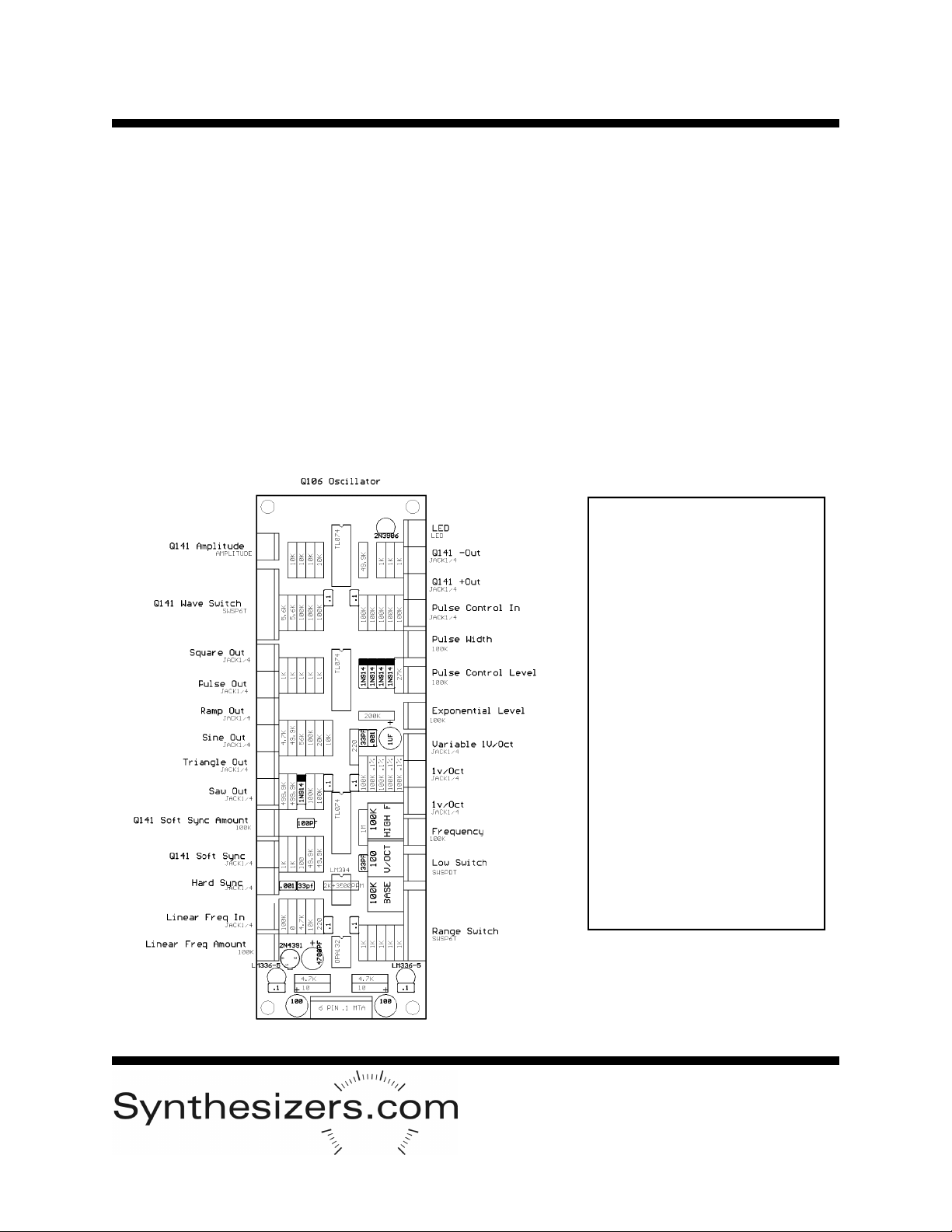
1. Connect the cables from the Q141 to the Q106 oscillator per the PCB drawing.
2. View the waveforms present at the +OUTPUT and –OUTPUT connectors while switching the
Waveform selector switch, and while adjusting the output level.
3. Apply a triangle waveform from another oscillator to the Soft Sync Input connector. Mix the
outputs of both oscillators (any waveforms). There should be no affect when the Soft Sync Amount
control is at 0, and various syncing results as the control is turned clockwise. Detuning the oscillators will
also result in various effects.
PC Board Layout
Q141 Installation
First, power down the system.
Remove the oscillator that the
Q141 will aid. It’s not necessary
to remove the power connector
if there is enough cable length.
There must be a single-width
blank opening to the left or to
the right of the Oscillator’s loca-
tion in which to mount the Q141.
There are 6 cables on the Q141
oscillator aid that must be con-
nected to the Q106 Oscillator.
Use the PCB drawing to locate
the connectors and attach the
cables.
Mount the modules in the cabi-
net.
*
*
* *
*
*