manuals.online logo
Brands
  1. Home
  2. •
  3. Brands
  4. •
  5. Synthesizers.com
  6. •
  7. Recording Equipment
  8. •
  9. Synthesizers.com Q109 User manual

Synthesizers.com Q109 User manual

Q109 Envelope Generator
Aug 2014
The Q109 Envelope Generator is one of the basic modules every synthesizer
must have. It generates a voltage envelope in response to a gate signal from a
keyboard, oscillator or other source. The envelope is used to control amplifiers,
filters, oscillators and other modules. The operator has complete manual control
over Attack time, Decay time, Sustain level, and Release time. A manual gate
button can be used to trigger the Envelope Generator at any time, and an LED
gives a visual indication of the output level.
Specifications
Panel Size: Single width 2.125"w x 8.75"h.
Attack Time Range: 1ms - 7+ seconds
Decay Time Range: 1ms - 12+ seconds
Release Time Range: 1ms - 12+ seconds
Sustain Level Range: 0-5 volts
Output Level: 0-5 volts
Gate Threshold: 1.5 volts
Power: +15V@30ma, -15V@30ma, +5@5ma.
Waveforms
Q109 Envelope Generator
Aug 2014
LED indicates the
output voltage
This controls the length
of the Attack phase
of the envelope.
The Attack phase
goes from 0 to 5 volts.
This controls the
sustain voltage level
after the Decay phase.
This voltage remains as
long as the Gate is on.
The Release phase
begins when the Gate
signal turns off.
Manual Gate button
is mixed with the
gate signal.
This controls the length
of the Decay phase
of the envelope.
The Decay phase drops to
the voltage level set by the
Sustain level control.
This controls the length
of the Release phase.
The Release phase
finishes at 0 volts.
Envelope output.
Typically 0-5 volts.
Can be jumpered for
different levels/ranges.
Gate input.
0 volts = off, 5 volts = on.
Typically comes from
a keyboard controller
or a sequencer.
Q109 Envelope Generator
Aug 2014
Usage and Patch Tips
Basics
The envelope generator is usually triggered from the keyboard gate signal and creates a voltage that
changes over time (envelope). Envelope signals are used to change sound parameters over time - usu-
ally filters, amplifiers, and oscillators but really any voltage controllable parameter can be controlled.
Study the waveform pictures to understand what each control does to affect the envelope's shape. When
a gate signal goes high (key is pressed), the Attack phase begins. The time it takes for this attack phase
to complete is determined by the Attack control. The voltage will rise slowly until it reaches +5 volts. At
that time the Decay phase begins and its time it determined by the Decay control. The voltage will decay
to the voltage set by the Sustain level control and will stay there as long as the gate signal is high (key
pressed). When the gate signal goes low the release phase begins and its time is set by the Release con-
trol. If you turn the sustain level full clockwise, there will be no decay phase.
Routing
Since you often need a separate envelope generator for filters and amplifiers, use a Q124 Multiple to
route a single gate signal from the keyboard to several envelope generators.
Inverted, Amplified, Attenuated Envelopes
Some module's inputs have inverters and attenuators that allow you to modify the envelope's affect on the
parameter, but some do not due to space constraints. Use a Q125 Signal Processor to invert, amplify,
attenuate, or offset an envelope signal.
Voltage Levels
The output of the envelope generator is 0 to 5 volts. The Q108 Amplifier responds well to this voltage
range (0 volts = off, +5 volts = full on) so you can patch the envelope directly into the control input of the
amplifier. If you need the envelope to span a larger range such as -5 to +5 volts, simply use a Q125
Signal Processor to amplify the signal by 200% then offset it by -5 volts. This expanded envelope voltage
range can be useful when you want to sweep the Q107 Filter its entire range.
Gates and Triggers
A gate signal stays on as long as a key is pressed, but a trigger signal is a very short pulse that only oc-
curs at the beginning of a keypress. The envelope generator can be started by a gate or a trigger with
different results. When using a gate signal to start the envelope generator, all controls act upon the wave-
form as you would expect, but when using a trigger signal to start it you'll loose the attack and decay con-
trol (Set them to 0). The Sustain and Release controls will work as expected. The result will be the same
regardless of how long you hold down a key.
Starting Envelopes from other Sources
Envelopes are usually started from keyboard gate signals, but you can use an oscillator or a sequencer to
start them too. When using an oscillator to continuously start an envelope generator, you essentially are
creating an oscillator with a customized waveform. Any of the gate signal outputs or the Done output on
the Q119 Sequential Controller can be used to start an envelope generator too. You can start an enve-
lope at a certain stage of a sequence by using a bank's (in 3x8 mode) output signal. Set all of the controls
for the bank to 0 except the stage that you wish to fire which should be set to +5.
Delaying Envelope Triggering
You can delay the triggering of the Q109 using the Q105 slew limiter. Simply run your gate signal
through the Q105. Setting the direction to Up will let the Amount control adjust the delay of the beginning
of the output gate. Setting the direction to Down will let the Amount control adjust the extension of the
output gate. Setting the direction to Both will let the Amount control adjust both the beginning delay and
the
extension resulting in a shifting of the entire gate signal.
Combining Delayed Envelopes to Create Complex Patterns
Using 2 Q109's, trigger one from an unmodified gate signal (possibly from a keyboard or sequencer),
and also patch the gate into a Q105 to create a delay for the second Q109. Combine the outputs of the 2
Q109 Envelope Generator
Aug 2014
Calibration and Testing
This module requires no calibration.
1. Turn the Attack, Decay and Release controls to 0.
2. Apply a 10hz 10v PP square wave to the Gate input.
3. View the output on an oscilloscope.
4. Turning Attack clockwise should make a longer attack
section of the waveform.
5. Turning Decay clockwise should make a longer decay
section of the waveform.
6. Turning Sustain clockwise should make a higher sustain
level of the waveform.
7. Turning Release clockwise should make a longer release
section.
8. Remove the Gate input, set all controls to 0 except
Sustain to 10.
9. Pressing the Gate button should cause the LED to come
on.
PC Board Layout
Power Connector
6 pin .1” MTA type connector made
by AMP. Available from Mouser
Electronics or Digi-Key. Modules
have a male PCB mount connector
and cable harnesses have a female.
Part Numbers:
Female cable mount: #6404416
Male PCB mount: #6404566
Pinout:
1 = +15v
2 = key (pin removed)
3 = +5v
4 = gnd
5 = -15v
Not all voltages are used on all mod-
ules.
J4 J5

Other Synthesizers.com Recording Equipment manuals

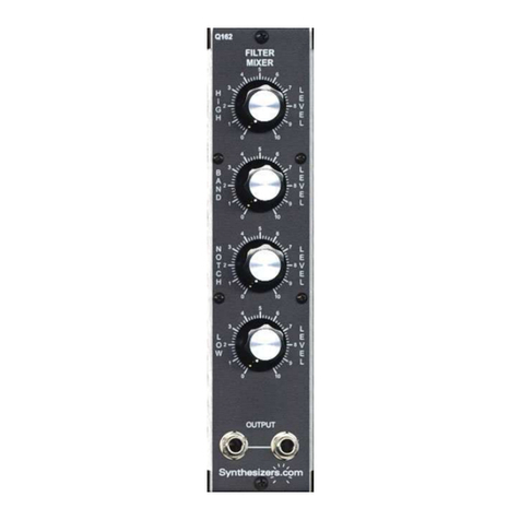
Synthesizers.com Q162 User manual

Synthesizers.com

Synthesizers.com Q162 User manual

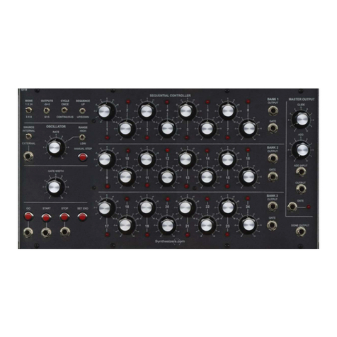
Synthesizers.com Q106 User manual

Synthesizers.com

Synthesizers.com Q106 User manual

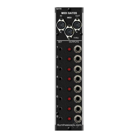
Synthesizers.com Q170 MIDI Gates User manual

Synthesizers.com

Synthesizers.com Q170 MIDI Gates User manual

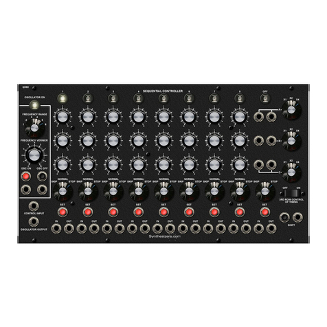
Synthesizers.com Q119 User manual

Synthesizers.com

Synthesizers.com Q119 User manual

Synthesizers.com Q150 User manual

Synthesizers.com

Synthesizers.com Q150 User manual

Synthesizers.com Q960 User manual

Synthesizers.com

Synthesizers.com Q960 User manual

Popular Recording Equipment manuals by other brands

Worthington DIATROL Installation & operation instructions

Worthington

Worthington DIATROL Installation & operation instructions

Tekbox TBS06 manual

Tekbox

Tekbox TBS06 manual

Alesis NanoVerb Stereo Amplifier Reference manual

Alesis

Alesis NanoVerb Stereo Amplifier Reference manual

SOMFY Connect UAI quick start guide

SOMFY

SOMFY Connect UAI quick start guide

Shure PS9 quick start guide

Shure

Shure PS9 quick start guide

midiplus miniEngine USB owner's manual

midiplus

midiplus miniEngine USB owner's manual

Sony WX-C55 Service manual

Sony

Sony WX-C55 Service manual

Qstarz BT-Q1000eX user manual

Qstarz

Qstarz BT-Q1000eX user manual

Kvaser USBcan R v2 user guide

Kvaser

Kvaser USBcan R v2 user guide

Aiwa CSD-A510 Service manual

Aiwa

Aiwa CSD-A510 Service manual

Roland Rhythm Composer TR-505 owner's manual

Roland

Roland Rhythm Composer TR-505 owner's manual

Panasonic WJHD100 - DIGITAL DISC RECORDE operating instructions

Panasonic

Panasonic WJHD100 - DIGITAL DISC RECORDE operating instructions

Cochlear Baha 5 SuperPower user manual

Cochlear

Cochlear Baha 5 SuperPower user manual

Akai MPC 5000 datasheet

Akai

Akai MPC 5000 datasheet

Paia 4712 Assembly and using manual

Paia

Paia 4712 Assembly and using manual

Mitsubishi Electric MR-J3-B user manual

Mitsubishi Electric

Mitsubishi Electric MR-J3-B user manual

Fostex R8 owner's manual

Fostex

Fostex R8 owner's manual

Dedicated Micros SD Range Installation and operation guide

Dedicated Micros

Dedicated Micros SD Range Installation and operation guide

manuals.online logo
manuals.online logoBrands
  • About & Mission
  • Contact us
  • Privacy Policy
  • Terms and Conditions

Copyright 2025 Manuals.Online. All Rights Reserved.