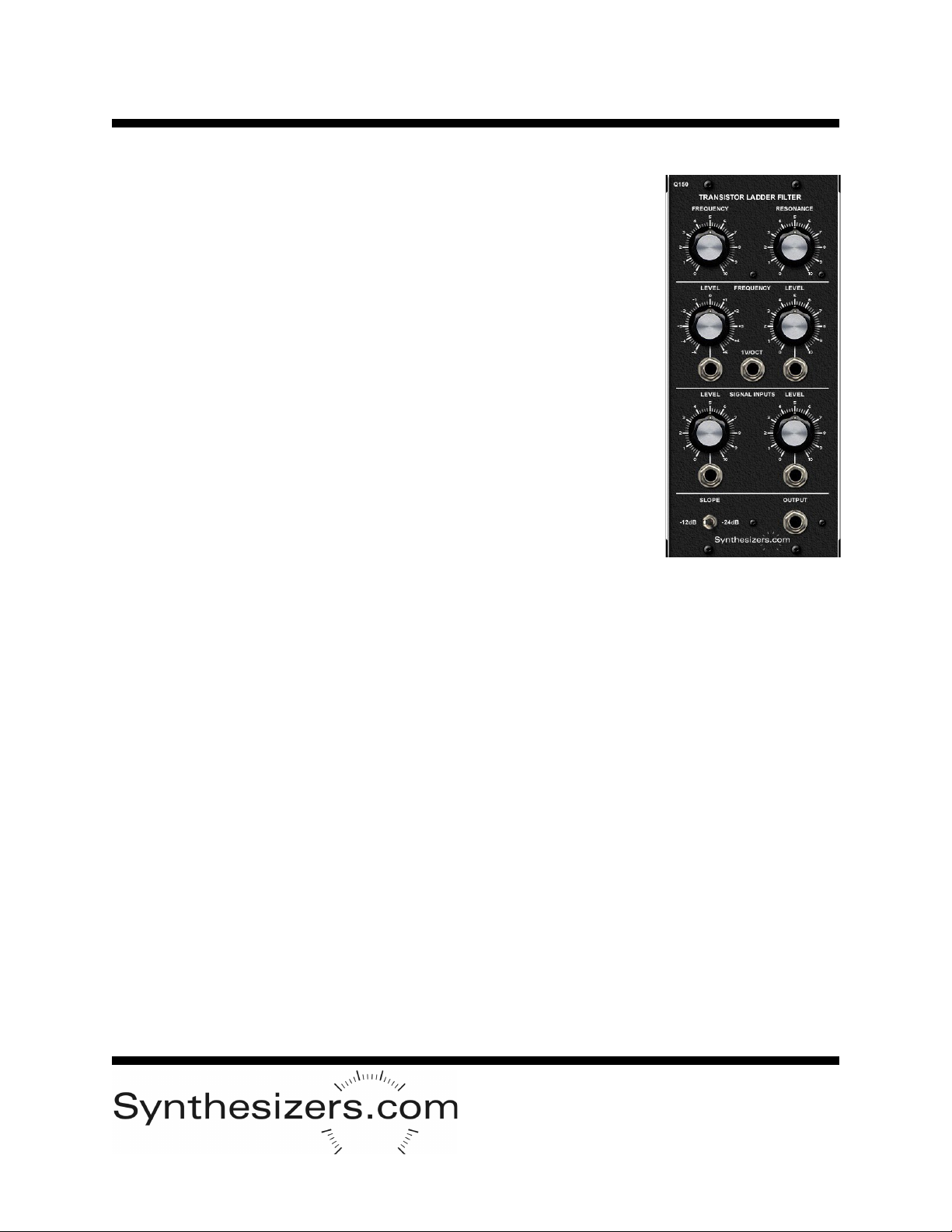
Q150/Q150A Transistor Ladder Filter
Usage and Patch Tips
Basics
Most waveforms contain many different frequencies. When an oscillator produces a sawtooth waveform, it
can be thought of as a single sine wave, and additional sine waves which are at multiples of the funda-
mental frequency and are at lower amplitudes. These additional frequencies are called harmonics and
different waveforms have different amounts. The Q150 Filter changes the way a waveform sounds by
attenuating (lowering the amplitude) of these harmonics. This effect is especially useful when changing
over time. The frequency at which attenuation starts (or close enough) is called the cutoff frequency. Cut-
off frequency can be controlled manually or by voltage control. Resonance (also known as Q, Regenera-
tion, or Emphasis) has the affect of enhancing frequencies near the cutoff frequency.
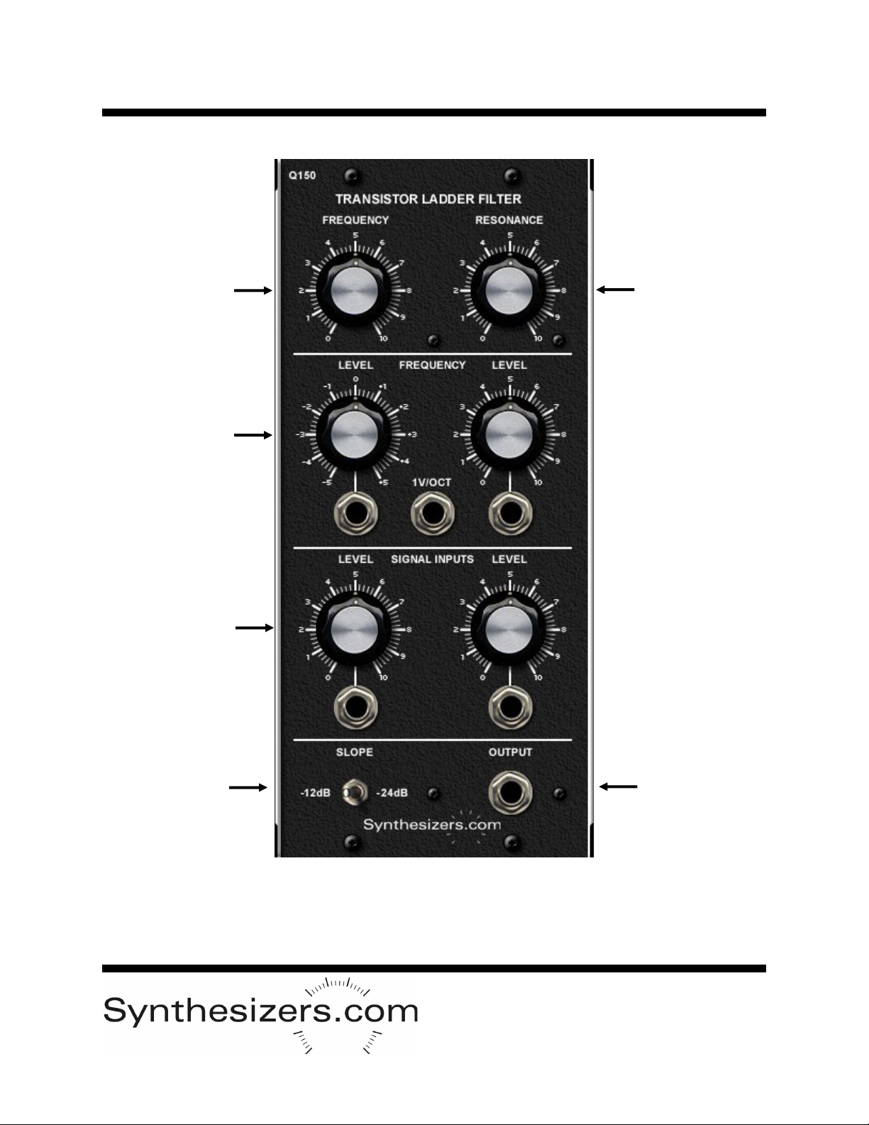
Frequency Control
The frequency control gives you about 10 octaves of cutoff frequency response. The control inputs are
added to the manual control's value to create the final cutoff frequency. All of these signals work together
at the same time to set the filter's cutoff frequency.
It's very common to have your filter track the keyboard so that the response is the same over all frequen-
cies. This is accomplished by using the 1V/Octave frequency control input. Simply patch your keyboard
pitch voltage into a multiple then out to your oscillators and to the filter.
The other frequency control inputs normally come from an Envelope Generator or from an Oscillator. You
can attenuate, amplify or invert the incoming control signal right on the filter instead of having to use an-
other module. The 0 to +5 volt outputs of the Q109 Envelope Generator will give you a total of 10 octaves
of range when the attenuator is full on.
The Sequential Controller can also be used to control the filter frequency. You could use one bank to con-
trol an oscillator and another to control the filter at the same time.
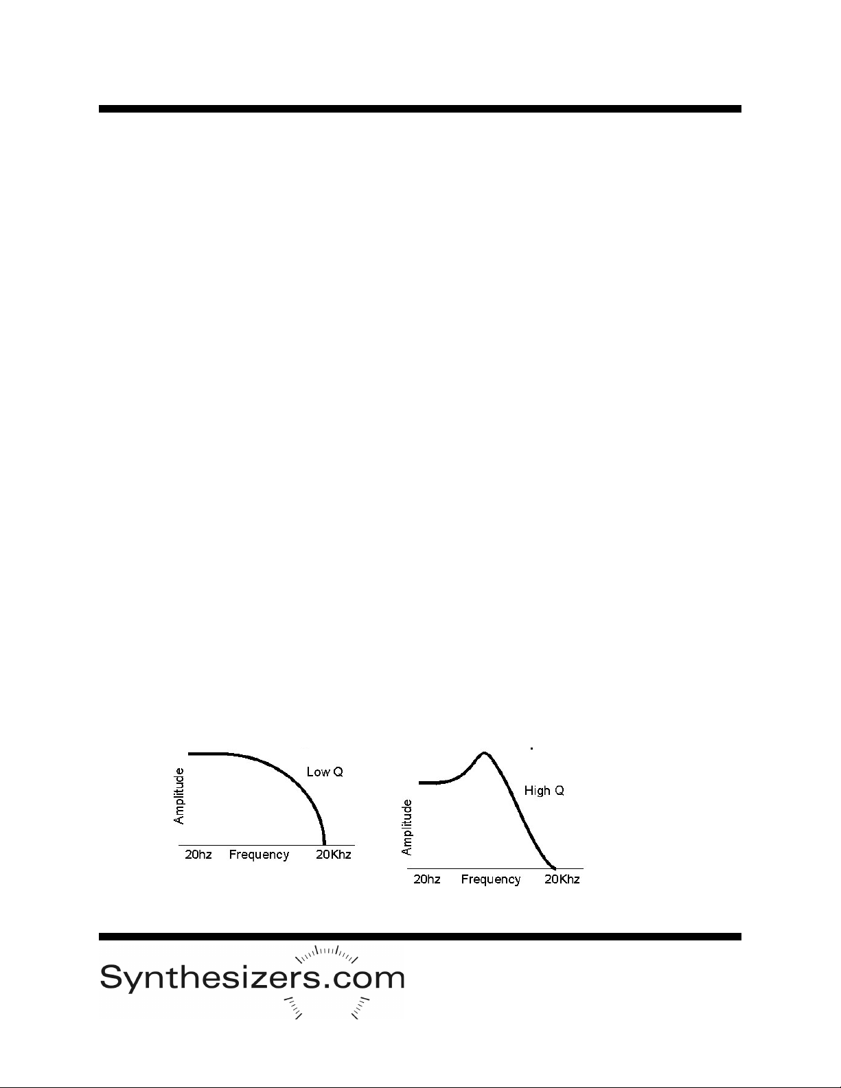
Resonance Control
Resonance is the emphasis of frequencies near the cutoff frequency and has a great affect on the sound.
The range of the resonance control is very large. If you have too much resonance the filter might oscillate
and clip. We let you decide if this is good or not. You can increase the maximum resonance possible by
turning down the input signal level control so that there is more room for resonance without clipping.
Self-Oscillation
Turning the resonance to maximum without an input signal will cause the filter to self-oscillate. This allows
the filter to act like an oscillator creating a very pure sine wave. Oscillation works best in –24dB mode.
Signal Inputs
There are 2 signal inputs which are mixed together - both are adjustable. Normally you will adjust the
input levels to 50% or less to allow larger resonance peaks.
Outputs
The output is available at the bottom of the module. A switch allows selection of -12dB or -24dB slopes.
Traditionally ladder filters have had -24dB slopes but we are also offering the -12dB slope to give you
even more sound possibilities.
A sine wave has almost no harmonics and will only respond to the filter by lowering its amplitude. Saw-
tooth and Ramp waveforms have the most harmonics and respond quite nicely to filtering. Square and
Pulse waveforms also have a great deal of harmonics and respond well to filtering.
Dec 2018