Synthesizers.com Q960 User manual

Q960 Sequential Controller
Sep 2014
The Q960 is an 8 stage, 3 row sequencer with an internal oscillator. Each row can control any volt-
age-controlled module such as an oscillator, filter, etc. A 9th stage provides a place for the se-
quencer to stop. A lamp for each stage indicates when it's active.
The front panel is divided into 3 sections: Oscillator, Stages, and Output. Each stage has 3 knobs
which determine the voltage at the 3 row outputs (A, B, C). The row outputs can be scaled using the
'X' switches (X1, X2, X4). A mode switch for each stage selects Skip, Normal, or Stop. A trigger
(Gate) input signal will select a particular stage, as does the manual push button. A trigger (Gate)
output signal is available when a stage is active.
The oscillator has 6 ranges and a variable control. A lamp indicates when the oscillator is on.
Both manual and Triggers (Gates) can control the oscillator's on/off condition. Voltage control of the
oscillator frequency is also available with an accurate temperature compensated 1V/Octave re-
sponse. An external shift input and manual button provide additional control of stage activation.
Specifications
Panel Size: Single width 17"w x 8.75"h.
Trigger, Shift, Control Input Signals: Fast rising 0-3 volts minimum, active high
Output Voltage Levels: 0 to 8V
Internal Oscillator: .1 to 2Khz +, 1V/Octave Response
External Oscillator Speed: 2Khz maximum
Power: +15V@120ma, -15V@30ma, +5@5ma.
The Q960 Sequential Controller is a recreation of Bob Moog's famous 960 module. Built using modern
components yet retaining the 960's unique functionality including the highly sought-after skip function, 3rd
row timing control, trigger in/out for each stage, etc. The Q960 consumes 8 spaces (17" wide) just as the
Moog 960, and uses the standard Synthesizers.com power supply (+15,-15,+5).

Q960 Sequential Controller
Sep 2014
The Q960 Sequential Controller is an 8-stage sequencer with 3 rows. An internal oscillator can control
the shifting speed, or an external source. Stages can also be selected manually or from external gates.
The Q960 can be used a 24-stage sequencer using the Q962 Sequential Switch module.
Internal oscillator with
manual or voltage control
of start/stop and speed.
A lamp indicates which
stage is active. The
active stage knobs produce
voltage at the output. Sets range of the
voltage outputs.
Control Input is a
1V/Octave control of
the internal oscillator
so the sequencer can
be used as a waveform
generator.
Oscillator output is a
90% pulse that can
drive envelope
generators.
Each stage can be
activated by a gate
or by a button.
Each stage has a gate
output (100% duty cycle).
Manual shift or exter-
nal shift to next stage.
The 3rd row knobs can
be used to control how
long each stage stays
active.

Controls and Connectors
Oscillator Lamp
Indicates the on/off condition of the internal oscillator.
Oscillator Range
Selects one of 6 oscillator frequency ranges.
Range 1: .05Hz - .46Hz
Range 2: .13Hz - 1.2Hz
Range 3: .5Hz - 4.7Hz
Range 4: 2Hz - 19Hz
Range 5: 8Hz - 75Hz
Range 6: 31Hz - 280Hz
Frequency Vernier
Variable control of oscillator frequency. Approximately a 1 to 9 range.
Oscillator On/Off Buttons
Manual control of oscillator operation.
Oscillator On/Off Inputs
Voltage control of oscillator operation. Typically a gate (trigger) signal, Oscillator square wave, etc.
Oscillator Voltage Control Input
Voltage control of oscillator frequency. 1 Volt per octave, temperature compensated.
Oscillator Output
Pulse wave oscillator output with a 90% (Default) duty cycle. 0-5 volts.
Stage Lamp
Indicates a stage is active. Normally only one stage is active at a time.
Stage Control Knobs
The knobs of the active stage determine the voltage at the row outputs.
Stage Mode Switch
Selects Skip, Normal, or Stop modes. Normal: A stage comes on, stays on for the duration of the
oscillator cycle, then turns off and shifts to the next stage.
Skip: Removes the stage from the shifting sequence.
Stop: Prevents shifting to the next stage. The oscillator remains on.
Stage Set Buttons
Allows manual selection of a stage and resets the other stages.
Stage Trigger Inputs
Trigger (Gate) input signals cause stage selection and others to reset. This can be a keyboard gate,
a pulse from an oscillator, a trigger output from another stage or sequencer, etc.
Stage Trigger Outputs
When the stage is active, a trigger (Gate) output is available at this jack. The output stays on as long
as the stage is on.
Continued on next page…….
Q960 Sequential Controller
Sep 2014

Typical 24-Stage Patch
Stage 9
A special 'Stop' stage where zero volts is sent to row outputs. Stage 9 can be Skipped with the mode
switch, activated manually with the Set button or activated with a trigger input. Stage 9's trigger output
is available as long as the stage is active (Lamp on). Whenever stage 9 becomes active, the oscillator
is automatically turned off.
Row 'X' Switches
Determines the range of the control knobs for each of the 3 row outputs. X1 = 0-2 volts, X2 = 0-4
volts, X4 = 0-8 volts.
Outputs
2 outputs provide the voltage of the selected stage control knobs.
3rd Row Control of Timing Switch
Routes the output of the 3rd row to the oscillator to control frequency. When a stage knob is set to 0,
there will be no affect on the oscillator frequency. Each volt output will double the oscillator frequency
resulting in a halving of the stage On time. Row C's X switch does affect this.
Shift Input
Control of shifting from an external signal such as an oscillator, gate, trigger source. Can be used in
conjuction with the internal oscillator for unusual timing effects.
Shift Button
Manual control of shifting.
Q960 Sequential Controller
Sep 2014

Q960 Sequential Controller
Sep 2014
Usage and Patch Tips
The Synthesizers.com Q960 is functionally equivalent to the Moog 960 and any Moog documentation will
apply. The Q960 however, has a few features that go beyond the Moog module such as the optional Re-
set mode, and intuitive cross-trigger patching.
For starters, you may want to read over the original Moog 960 information at Roger Luther's Moog Ar-
chives From the menu on the left, select INSTRUMENTS, then select MODULES. Don't forget to send a
note to Roger Luther for his great website.
Triggers and Gates
In the Moog language, Triggers are what we call Gates today. Triggers and gates are On/Off signals that
indicate an on/off event such as a keypress or stage on. Learn more about gates and triggers in this arti-
cle.
Controlling Envelope Generators
Normally, the oscillator output of the Q960 is used to start an envelope generator on every stage activa-
tion. The oscillator output is fixed at 90% duty cycle (90% on, 10% off). You can also start Envelope gen-
erators using the individual stage trigger outputs. These trigger outputs are on for the entire time that a
stage is on (100% duty cycle). This means that 2 adjacent stages firing the same envelope generator will
create a single longer trigger when mixed together.
Combining Triggers with the Q961 Interface
Use the Q961 Interface to combine up to 12 triggers. Six trigger inputs are simply mixed together, and six
have an adjustable width. The adjustable width inputs allow adjacent triggers to create independent trig-
ger pulses.
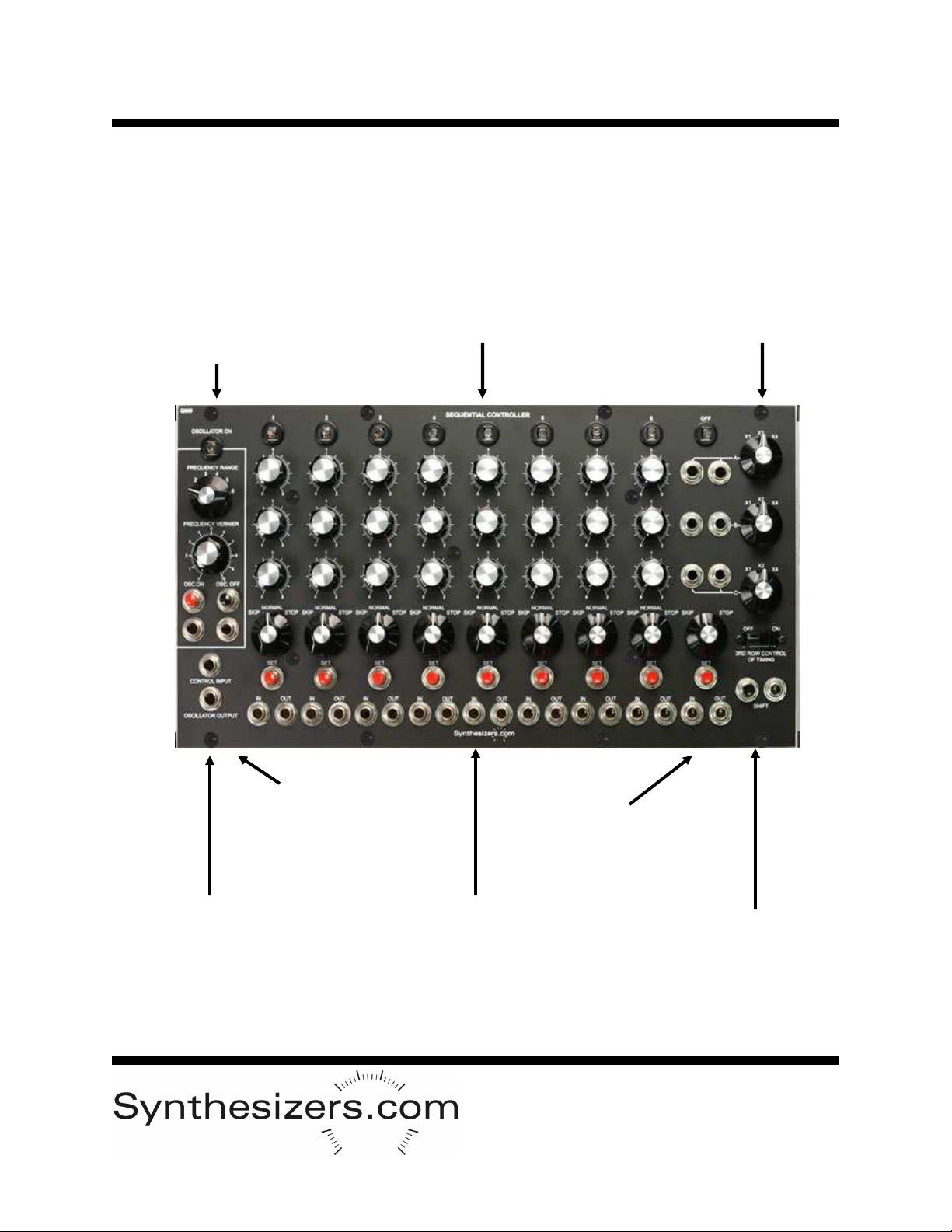
Row Control of Stage Timing
The timing of each stage can be controlled by the 3rd row of knobs (Row C) by simply switching the '3RD
ROW TIMING' rocker switch. This routes the voltage from the 3rd row back to the oscillators control volt-
age input. The oscillator's extra control voltage input can be used in addition to this. The X switch scales
the effect. Other rows can be used to control timing by simply patching the row output back to the oscilla-
tor's control voltage input.
When the X switch is set at X1, each knob produces 0-2 volts. Since the oscillator responds to the volt
per octave standard, setting the knob to the zero position causes no speed change, setting the knob to
the 1 position doubles the speed of that stage, and setting the knob to the 2 position quadruples the
speed of that stage. This makes timing settings easy to program.
Cross-Triggering
Cross-Triggering is the method of patching a trigger output from one stage to the trigger input of another.
Exotic, non-sequential patterns can be created using multiple patches. Patches can be enabled or dis-
abled using the Q962's switch section to create patterns that change from cycle to cycle.
Cross-Triggering carries with it unexpected results at times. For example, patching a trigger output to a
trigger input that has the mode switch set to skip, causes the sequencer to reset to stage 1. This is be-
cause triggering is not a shifting operation and a stage can not be selected via a shift pulse unless the
previous stage is active. A special circuit inside the Q960 resets to stage 1 when no stages are active.
In the same situation, the Moog 960 would cause multiple stages to come on at the same time resulting in
useless outputs and sequences. The Q960 varies from the Moog in this regard and the results are fun
and powerful.
It is possible to intentionally patch triggers so that multiple stages come on at the same time. The result is
that the voltages from each active stage is summed at the output stage.

Module Calibration
See the PCB Layout for location of each Trim Pot.
Oscillator Calibration
Calibration is done with 2 trim pots - base frequency and scale.
Attach a frequency counter to the oscillator output.
Attach a precision voltage source to the oscillator control input.
Set the voltage source to 0V.
Set the frequency vernier to 0.
Set the range switch to 5.
Adjust the base frequency trim pot to 8Hz.
Adjust scale trim pot so each 1V doubles the frequency.
Turn scale counterclockwise in 1/8 turn increments to bring the 2
frequencies together. Clockwise to move them apart.
Frequency at 6 volts should 512Hz within 1Hz.
Voltage Reference Calibration
Set Stage #1, Oscillator off.
Turn Row A X switch to X1.
Turn Row A, stage #1 pot full clockwise.
Adjust the trim pot to achieve exactly 2 volts at the row A output.
Power Connector
6 pin .1” MTA type connector made
by AMP. Available from Mouser
Electronics or Digi-Key. Modules
have a male PCB mount connector
and cable harnesses have a female.
Part Numbers:
Female cable mount: #6404416
Male PCB mount: #6404566
Pinout:
1 = +15v
2 = key (pin removed)
3 = +5v
4 = gnd
5 = -15v
Not all voltages are used on all mod-
ules.
24-Stage Operation using a Q962
One of the primary purposes of the Q962 sequential switch is to alternately select between the 3 row out-
puts of the Q960 to effectively create a 24 stage sequence. Patch the trigger output from stage 1 into the
shift input of the Q962. Patch 2 or 3 rows from the Q960 to the Q962's switch inputs. Now the Q962's out-
put will be the 24-stage sequencer output.
Multi-Sequencer Triggering
Of course, you can patch trigger outputs and inputs between multiple sequencers to achieve truely com-
plex and bizarre sequences.
Using the Q128 Switch to Select Cross Triggers
Use the Q128 Switch to select various triggering under voltage control. The Q128 can be controlled from
any source including a keyboard, another sequencer, a Q962 switch, an oscillator, etc. The results can be
amazing.
Pseudo-Random Stage Selection
Since the Q960 is a shifting style sequencer, the only way to get true random stage selection is to have a
source of multiple random triggers. A similar effect can be achieved by patching the output of a Q110
Noise module into the Q960 Shift input. The result is actually random shift timing but it acts similar to ran-
dom stage selection if tuned correctly.
Q960 Sequential Controller
Sep 2014

Q960 Sequential Controller
Sep 2014
PC Board Layout
Table of contents
Other Synthesizers.com Recording Equipment manuals

Synthesizers.com
Synthesizers.com Q119 User manual

Synthesizers.com
Synthesizers.com Q162 User manual

Synthesizers.com
Synthesizers.com Q109 User manual

Synthesizers.com
Synthesizers.com Q170 MIDI Gates User manual

Synthesizers.com
Synthesizers.com Q150 User manual

Synthesizers.com
Synthesizers.com Q106 User manual