
Synway Information Engineering Co., Ltd
Fit modules to board. Contacts on both sides greatly improve connection and ease
installation.
zModule Configurable
4 on-board dual-channel modules can be freely arranged in pairs or groups for various
complex, multi-functional applications.
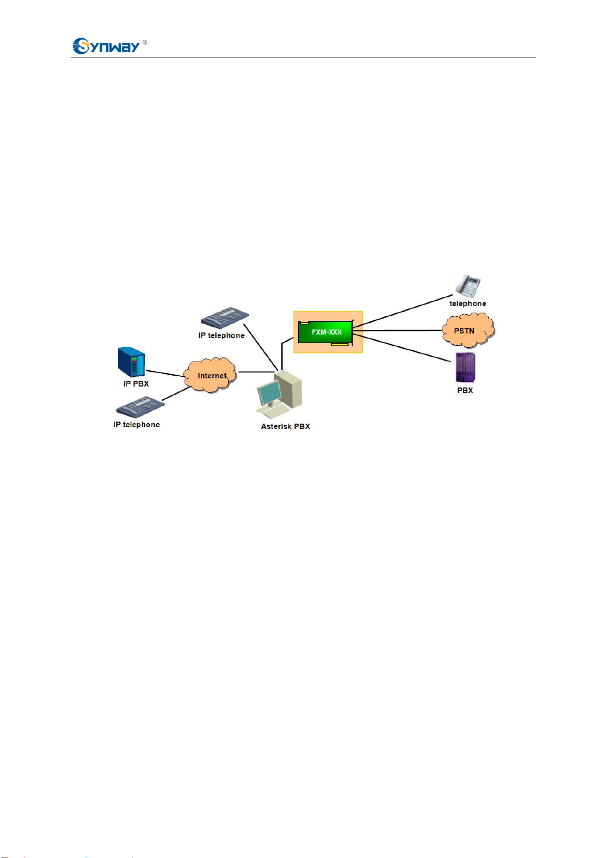
zRJ11 Jack
The on-board RJ11 jack can connect directly or via a proper 2-way hub with telephone lines,
making connection easy and malfunctions rare.
zExternal Ringing Current & Battery Feed Power Supply
Provides station modules with battery feed, and enables the phones which are linked to
station channels to ring.
zEcho Cancellation
The self-adaptive echo cancellation feature gives the board the capability of 128ms echo
cancellation so as to effectively eliminate echoes under various conditions, canceling out
the effect of voice playback on DTMF and busy tones detection, avoiding self-excited
oscillation and howling, and minimizing the possibility of registering wrong DTMF and busy
tones in a conference call, designed especially for VoIP application environments.
zVoice CODEC Support
Supports the hardware-based A-law, μ-law codecs. The recorded voice files can be edited
and played by audio tools such as Cooledit.
1.1.2 FXM-16A/PCIe Features
zPCI Express Bus Support
Includes PCI Express 1.0a bus with the single-way transmission rate up to 2.5Gb; supports
PCI Express X1, X2, X4, X8, X16 slots and DMA transfer.
zOn-board SIMM Slots
Fit modules to board. Contacts on both sides greatly improve connection and ease
installation.
zModule Configurable
8 on-board dual-channel modules can be freely arranged in pairs or groups for various
complex, multi-functional applications, such as call center and recording functions available
on a single board.
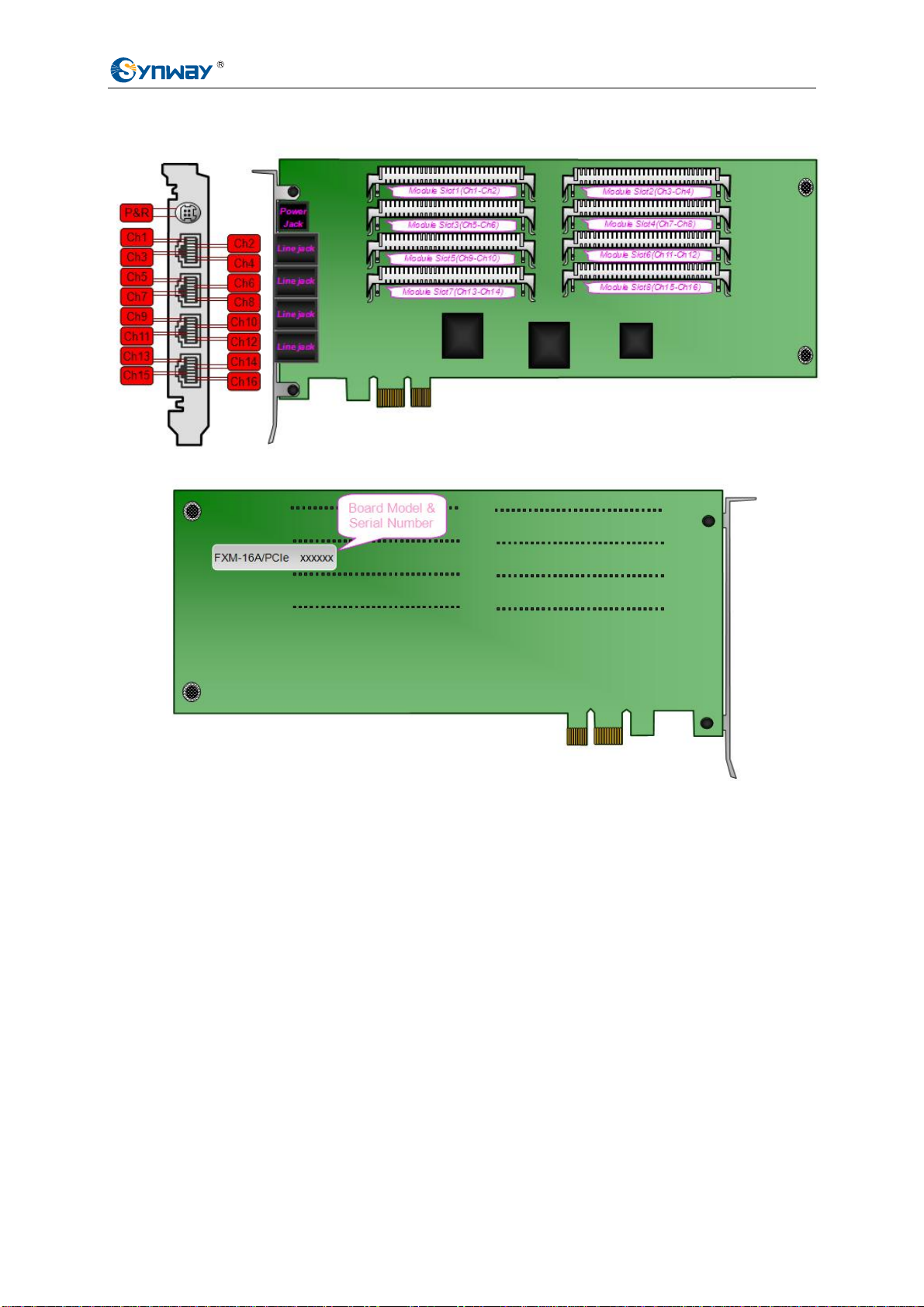
zRJ45 Jack
A single board has 4 8-pin RJ45 jacks, each of which can be converted to 4 2-pin RJ11
jacks via a four-way hub so as to connect with analog phone lines, making connection easy
and malfunctions rare.
Synway FXM series Hardware Manual
(
Version 1.0
)
Page 2


 User manual")


