2
1. Field of application
The SYR-Safe-T is an effective anti-leakage
system in compliance with recognized
international standards. It is adaptable to all
SYR anges from DN 20 to DN 32.
Fully automatic electronic anti-leakage system
with contacts for many different connection pos-
sibilities.
With two O-rings, a seal, small hexagonal so-
cket screws for the installation, a mounting key
and a oor sensor.
2. Model
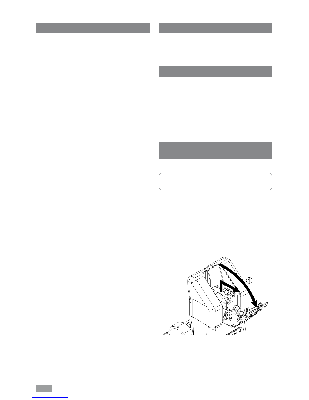
3. Inserting / Exchanging
batteries
Insert the batteries prior to using the Safe-T.
Open the upper battery door and remove the
battery block.
Table of contents
1. Field of application ................................... 2
2. Model ....................................................... 2
3. Inserting / Exchanging batteries ............... 2
3.1 Initial operation ................................ 3
4. General operation .................................... 3
4.1 Unlocking the keyboard ................... 3
5. User menu ................................................ 4
5.1 Leakage protection .......................... 4
5.2 Setting the leakage protection ......... 4
5.3 Deactivating the leak. protection ..... 5
5.4 Vacation leakage protection ............ 5
5.5 Setting the vacation leakage
protection ........................................ 6
5.6 Deactivating the vacation leakage
protection ........................................ 6
5.7 Stop valve ....................................... 7
5.8 Changing the stop valve‘s status .... 7
5.9 Re-opening the stop valve after
leakage ............................................ 7
6. Other settings ........................................... 8
6.1 48h-leakage .................................... 8
6.2 Changing the 48h-leakage mode .... 8
6.3 Time-based leakage (volume) ......... 8
6.4 Time-based leakage (ow rate) ....... 9
6.5 Unlocking the device ....................... 9
6.6 External alarm contact .................... 9
6.7 Buzzer ........................................... 10
6.8 Contact 1 ....................................... 10
6.9 Contact 2 ....................................... 10
6.10 Mounting conditions ...................... 11
7. System information ................................ 11
7.1 Serial number ................................ 11
7.2 Battery power ................................ 11
7.3 Alarm memory ............................... 12
8. Emergency unlock function .................... 12
8.1 Restart ........................................... 13
9. Technical specications .......................... 14
10. Connections ........................................... 14
11. Accessories ............................................ 14
12. Dimensions ............................................ 15
13. Messages ............................................... 16
Insert the battery block or exchange it (4 x LR
06) and put it back into place in the battery com-
partment.
Warning: The batteries have to be in-
serted even when using the mains plug!