SYR Safe-T Connect User manual

SYR Safe-T Connect
Operating manual
(translation of original version)

Imprint
Document type: Operating manual
Product: SYR Safe-T Connect
Target readership: authorised qualied technicians
Language: English
Document number_Version: 9.2421.32
Creation date: 20/2014
Issued/produced by
SYR Hans Sasserath GmbH & Co. KG
Mühlenstrasse 62
41352 Korschenbroich
© SYR Hans Sasserath GmbH & Co. KG
Copying of this manual, including of extracts, is only permitted with
the written permission of Hans Sasserath GmbH & Co. KG.
All product names mentioned in this manual
are the property of the
respective brand name
owners.
We reserve the right to make technical changes.

Contents
1. General ...............................................4
1.1. About this manual ..........................................4
1.2. Symbols used..............................................4
1.3. Copyright protection .........................................5
1.4. Warranty..................................................5
1.5. Applicable standards ........................................5
2. Safety.................................................6
2.1. Intended use ..............................................6
2.2. Fundamental risks ..........................................6
2.3. Risks from electrical energy ...................................6
2.4. Servicing and repair work.....................................7
3. Construction and operation ..............................8
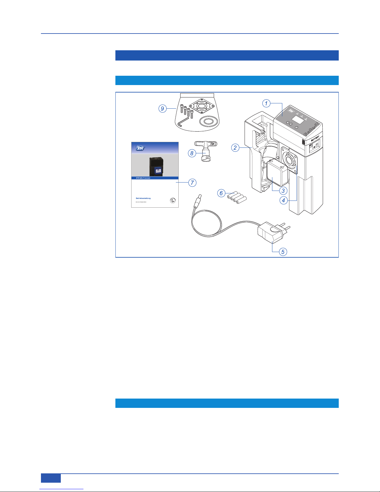
3.1. Contents of package ........................................8
3.2. Optionally available accessories ...............................8
3.3. Construction ...............................................9
3.4. Function .................................................10
4. Transport and storage ..................................10
4.1. Transport ................................................10
4.2. Storage..................................................10
5. Installation and commissioning ..........................11
5.1. Safety notices for installation and commissioning .................11
5.2. Installation ...............................................12
5.2.1. Fitting the universal ange ...................................12
5.2.2.Installation of the SYR-Safe-T Connect .........................12
5.3. Commissioning............................................14
6. Operation.............................................15
6.1. Controls on the Safe-T Connect...............................15
6.1.1. Congurable parameters ....................................17
6.1.2.Setting the presence leakage on the appliance
(without LAN cable plugged in) ...............................19
6.1.3.Emergency open function ...................................19
6.2. Control via SYR app........................................21
7. Service and maintenance ...............................22
8. Faults ................................................22
9. De-installation and disposal .............................23
9.1. Dismantling ..............................................23
9.2. Disposal .................................................23
10. Technical data .........................................24
10.1. Safe-T Connect ...........................................24
10.2. Flow performance .........................................24
10.3. Dimensions ..............................................25
3

General
1. General
1.1. About this manual
This operating manual enables you to operate your SYR Safe-T Connect leak-
age protection safely and efciently.
It is a supplied with the product and must always be kept accessible for the user.
Due to technical developments, images and descriptions in this operating man-
ual may differ from the Safe-T Connect leakage protection actually delivered.
We can accept no liability for damages caused by failure to comply with instruc-
tions in this manual.
1.2. Symbols used
All safety notices in this operating manual are marked with appropriate symbols.
The signal words at the beginning of the safety notice express the level of risk.
Danger!
This combination of symbol and signal word indicates a situation
that constitutes an imminent danger of death or serious injury if
it is not avoided.
Warning!
This combination of symbol and signal word indicates a situation
that constitutes a possible danger of death or serious injury if it
is not avoided.
Caution!
This combination of symbol and signal word indicates a situation
that constitutes a possible danger of minor injury if it is not avoided.
Note!
This combination of symbol and signal word indicates important in-
formation that will help to avoid material or environmental damage.
4

General
1.3. Copyright protection
The copyright for this operating manual and all documents supplied with this ap-
pliance remains the property of Hans Sasserath & Co. KG.
Their use in the context of using the appliance is both permitted and desired.
These documents may be neither reproduced nor made available to third par-
ties, in particular competing companies, without the express authorisation of
SYR.
Note that there is a patent protection for the SYR Safe-T Connect leakage pro-
tection.
1.4. Warranty
The manufacturer provides a warranty in accordance with the conditions of sale
and delivery.
Warranty claims become void if:
• damage arises from incorrect operation,
• repairs or modications are undertaken by unauthorised persons,
• original SYR accessories and spare parts are not used,
• defective components are not maintained promptly in or-
der to minimise the extent of damage and avoid compromis-
ing the safety of the appliance (maintenance obligation).
1.5. Applicable standards
The following European and national standards were applied during the devel-
opment and design of the SYR Safe-T Connect leakage protection:
• DIN EN 806
• DIN 1988
• DVGW VP 638
5

Safety
2. Safety
2.1. Intended use
The SYR-Safe-T Connect is an effective leakage protection in accordance with
DVGW VP 638 for dwellings. The appliance is adaptable to all SYR anges from
DN 20 to DN 32. A 100 % protection against water damage cannot be guaran-
teed for every possible system.
Any use other than or going beyond this is not an intended and proper use.
Intended use also includes compliance with this operating manual.
2.2. Fundamental risks
Certain risks are inherent in working with electrically operated equipment. You
should therefore observe the legal regulations for the protection of health and
safety (in Germany, VSG), any other generally recognised rules of health and
safety at work and the regulations of the professional associations (in Germany,
BGV).
Do not attempt to modify the SYR-Safe-T Connect. The manufacturer is not lia-
ble for damages arising from improper modications.
2.3. Risks from electrical energy
Warning!
Risk of crushing injury!
A soon as voltage is applied (mains adapter, battery), the system
moves to the closed position.
►Do not insert any body parts or objects into the valve opening.
Observe the prescribed values for voltage and current (see technical data) dur-
ing installation.
Work on electrical installations or the controller may be carried out only by qual-
ied electricians.
Before starting work, disconnect the network adapter and remove the batteries.
Regularly check the mains adapter and, if damaged, have it replaced by an
electrician.
Note:
Observe the technical
rules for safety installa-
tions such as re extin-
guishing lines, emergen-
cy showers, etc.
6

Safety
2.4. Servicing and repair work
Servicing and repair work may only be carried out by trained and authorised
specialists. These are persons who, on the basis of training, instruction or expe-
rience, have been authorised to carry out the required work and can recognise
and avoid the possible risks involved. They must be able to show that they know
the relevant safety standards, regulations and legal provisions and have read
the operating manual.
7

Construction and operation
3. Construction and operation
3.1. Contents of package
Fig. 1: SYR-Safe-T Connect package contents
Legend
1 Electronics unit
2 Insulating casing
3 Blanking cap
4 Leakage protection valve
5 Mains adapter
6 Batteries (4x AAA)
7 Operating manual
8 Key for emergency shut-off function
9 Sealing pack
3.2. Optionally available accessories
The following accessories are available to expand the functionality of the system:
• DN 20-32 ange
• Dru +, FF, FR, DFF, DFR drinking water lters
8

Construction and operation
3.3. Construction
1
3
11
9
2
4
5
7
6
8
10
Fig. 2: SYR-Safe-T Connect construction
Legend
1 LCD display
2 LEDs for status indication
3 Control buttons
4 Battery compartment
5 Mains adapter connection (9 V DC)
6 Connection for humidity sensor
7 LAN connection
8 Flow sensor
9 Temperature sensor
10 Pressure sensor
11 Insulating casing
9

Transport and storage
3.4. Function
SYR Safe-T Connect is an effective leakage protection system that complies
with DVGW VP 638. It is adaptable to all SYR anges from DN 20 to DN 32.
Thanks to continuous monitoring, a leak is recognised early and water damage
is limited by automatically shutting off the water supply.
The Safe-T Connect with integrated LAN connection has electronic water me-
tering (by means of a turbine), an electrically actuated shut-off, a pressure sen-
sor to monitor the smallest leakage quantities and a multifunctional display.
When installed, it has a permanent encoded link to a server, which polls it to ob-
tain data from the drinking water installation such as: volumetric ow, total ow
per unit time, duration of the volumetric ow, pressure drop and temperature.
The maximum permissible parameters can be congured or changed directly
on the Safe-T Connect or via software on a smartphone or PC. Even if there is a
loss of Internet connectivity, the parameters will continue to be monitored. How-
ever, there will be no communication with the server during this time.
Energy is supplied via the mains adapter. Batteries to provide a short-term back-
up in the event of a power cut are supplied.
4. Transport and storage
4.1. Transport
The unit is delivered pre-assembled.
Its weight is approx. 1,720 g.
Note!
Possible material damage by improper transport!
The packaging provides transport protection.
► If there is signicant damage to the packaging, do not install
the appliance.
►After heavy impacts or blows, exchange the plastic part affect-
ed even if there is no visible damage.
4.2. Storage
Store the appliance only under the following environmental conditions:
• Temperature: +4 to +60°C, Relative humidity: max. 80%
Note!
Possible material damage by improper storage!
►Protect valves and electronics from frost.
10

Installation and commissioning
5. Installation and commissioning
5.1. Safety notices for installation and commissioning
Installation and commissioning of the SYR Safe-T Connect may only be carried
out by authorised trained and instructed specialists, who have the appropriate
knowledge.
Compliance is required with the applicable safety provisions for drinking water
installations. These include (for Germany):
• TRWI - DIN 1988-200, EN 806, EN 1717,
• The regulations and provisions of the local water supply authority.
Note!
Possible material damage due to improper drinking water instal-
lation!
Improper installation of the SYR universal ange can lead to leak-
age in the drinking water supply system.
► Fit the universal ange in accordance with the instructions for use.
Test the connection for leaks.
►Avoid water hammer effects, e.g. from downstream solenoid
valve.
Note!
Contaminants in the drinking water can cause corrosion prob-
lems and lead to malfunctions of the valves.
► We recommend the installation of a lter (e.g. Dru + DFR) to
protect the downstream installation.
Note!
Possible material damage by improper drinking electrical instal-
lation!
►Connect the unit to the mains supply only with the mains adapt-
er supplied.
11

Installation and commissioning
5.2. Installation
►Shut off the water supply before starting installation work.
5.2.1. Fitting the universal ange
►Install only in drinking water installations in accordance with DIN 1988, im-
mediately after the water metering system.
►Fit in accordance with the instructions for use of the SYR universal ange.
5.2.2. Installation of the SYR-Safe-T Connect
The SYR-Safe-T Connect is adaptable to all SYR anges from DN 20 to DN 32.
If a SYR DRUFI + pressure reducer-lter combination is already installed, this
installation must not be altered.
The Safe-T Connect should be installed between the lter and ange.
►Mount the Safe-T Connect (2, g. 3) on the ange (1) with the four Allen
screws and gasket.
►Close off the front ange connection with a blanking cap (3, art. No.
2320.00.901) or connect a SYR DRUFI + (4) at this point.
Fig. 3: Safe-T Connect installation
►Open the water supply.
►Test all valve connections for leaks.
Note:
Fit the universal ange
free of applied stress!
It is essential to observe
the ow direction!
Note:
In the case of continu-
ous drawing (e.g. lling
a swimming bath) and in
combination with safe-
ty valves (e.g. thermal
run-off protection 3065)
a branch separate from
the Safe-T plus must be
made!
12

Installation and commissioning
►Insert four batteries (2; size AAA) in the battery compartment. Observe the
correct polarity!
2
Fig. 4: Battery insertion
►Connect a network cable (1, g. 5) and the mains adapter (2) to the Safe-T
Connect.
1
2
Fig. 5: Connections to the Safe-T Connect
►Plug the network cable and the mains adapter into the sockets provided.
►Optional: connect the humidity sensor.
Note:
The batteries must be
changed after no more
than two years.
Do not use rechargea-
ble batteries!
Inform the owner-opera-
tor accordingly!
Note:
When
using a Power-
Line or similar for the
Internet connection, the
appropriate manufactur-
er’s information is to be
observed!
13

Installation and commissioning
►Replace the insulating casing shells.
Fig. 6: Replacing insulating casing
5.3. Commissioning
The Safe-T Connect starts working as soon as voltage (mains adapter, batter-
ies) is applied.
The system goes into the “closed” position.
►Press the button.
The system goes into the “open” position and changes to the normal operating
state.
You can make all the required settings directly on the Safe-T Connect, with the
SYR app on your smartphone or via a PC.
The SYR app is available free of charge from the App Store.
Other operating systems can use an app-like application with their Web browser
from http://syrconnect.de or http://syrconnect.com.
Over Internet connections, settings can be made only using the SYR app or a
web browser.
Note:
Dynamic Host Cong-
uration Protocol (DH-
CP) must be available
and enabled on the In-
ternet router so that the
Safe-T Connect is auto-
matically assigned an IP
address.
Note:
If batteries are insert-
ed but the mains adapt-
er is not connected, the
notice “Please connect
mains adapter” will ap-
pear.
14

Operation
6. Operation
6.1. Controls on the Safe-T Connect
The user interface of the appliance consists of a four-line LCD display, three
LEDs for status indication (pulse, fault and SYR Connect) and three control but-
tons ( , and ).
PulseFault
Fig. 7: User interface with display, LED and control buttons
Symbol Button/LED Meaning
Enter Conrm and save the data entered or change menu.
Decrease for changing values
Increase for changing values
yellow LED Pulse indicates ow (LED ashes)
red LED Fault indicates fault (LED lights up)
green LED SYR Connect Connection made to server (LED ashes)
The following graphic shows sections of the menu structure of the Safe-T Connect:
15

Operation
Basic Safe-T plus menu
Leakage at 100 L
Shut-off OPEN
P = 3,2 bar
Operating states that are shown in the basic menu
Q = 380 l/h Temporarily off 0:59 h Valve closes… No mains voltage Battery change No SYR-Connect
Flow > 3500 l/hRun-off sensor/LP of Micro-leakage test Alarm/fault
Basic settings menus
PARAMETER/INFO
Basic setting
Expert setting
Appliance info Shut-off
100 L 20 LNoOPEN
MODE MODE…
Menus for the extended user settings
PARAMETER/INFO
Basic setting
Expert setting
Appliance info
Back German
°F/psi/US.lig.gal
2 hour(s)
1
min. ON OFF
MODE, DOWN MODE…
Expert settingExpert settingExperteneinstellungExpert settingExpert setting Expert setting
Expert setting Expert settingExpert settingExpert settingExpert settingExpert setting Expert setting
Ext. input
Ext. leakage sensor monatlich 45% 90%
Language UnitsLeakage time Leakage flow Auto-unlockExt. fault alarmAlarm buzzer
Shut-off OPEN
Shut-off OPEN
Shut-off OPEN Shut-off OPEN Shut-off ? Shut-off OPEN Shut-off OPEN Shut-off OPEN
Shut-off OPEN Shut-off OPEN Shut-off OPEN Shut-off OPEN
Back
ON
ON
Pulse (push button)
OFF
Leakage at 100 L Leakage at 400 L Leakage at 10 L Leakage at
- -
Leakage at
100 L
Leakage at
100 L
Leakage at
100 L
Leakage at
100 L
Leakage at
100 L
Leakage at
100 L
Leakage at
100 L
Leakage at
100 L
PRESENT PRESENT PRESENT PRESENT PRESENT PRESENT PRESENT
PRESENT PRESENT PRESENT PRESENT
PRESENT
ABSENT
PRESENT, level 400 lWater drawing Absent, level 20 l
Leakage protection
temporarily off
Shut off Mains adapter missing Batteries flat No Internet
Max. flow Run-off sensor activeML test activeFault (leakage)
Away level
Basic setting Basic setting Basic setting Basic setting
Present level Leakage protection off
Floor sensorMicro-leakage test
LCD contrast LCD brightness
Fig. 8: Sections of the menu structure of the Safe-T Connect
16

Operation
6.1.1. Congurable parameters
The following table shows the congurable parameters.
Parameter Adjustment range Factory setting
Start menu
Presence leakage
(at home level) 100 l ... 1,500 l 400 l
Absence leakage
(away level) Off, 10 l ... 100 l Off
Leakage protection
temporarily off 0 .. 8 hrs No
Shut-off Open, closed Open
Extended settings (expert level)
Sprache/Language German, English German
Units °C/bar/litre German
Leakage time Off, 0.5 ... 25 hours 1.5 hrs
Leakage ow 1 ... 99 minutes 1 min.
Auto-unlock On, off Off
External error message Off, NO, NC, Pulse, Ext. valve
control Off
Alarm buzzer On, off On
Floor sensor On, off On
External input Off;
Pulse (push button) Ext. leak-
age sensor;
NC (switch) Ext. leakage sensor;
NO (switch) Ext. leakage sensor;
pulse (push button) remote-
ly actuated open/closed; NC
(switch) remotely actuated
open/closed; NO (switch) re-
motely actuated open/closed
Off
Micro-leakage test
Off, message only, shut-off
Off
LCD contrast 0 ... 100% 45%
LCD brightness 0 ... 100% 90%
17

Operation
Parameter Adjustment range Factory setting
System and device information
Firmware Safe-T Connect VX.X
Serial number 12345678
Code number 123456789
Battery voltage 0 ... 6 V.
Temperature
Error log
Some important terms in the menu are explained in the following table with
examples.
Function Explanation
Presence leakage Maximum possible water ow after opening a drawing point without
time limitation
Example:
The drawing with the highest ow is the bathtub. The capacity of the
bathtub is about 120 litres. Set the presence leakage value to 200 li-
tres
Absence leakage More stringent monitoring of the maximum possible water ow when
the user is away for a longer period (holidays, etc.).
Example:
If the user is absent for a longer period, the absence leakage value
setting should be relatively low. For an occasional drawing, e.g. wa-
tering the house plants, a value of 10 litres is sufcient.
Leakage ow
If a water ow > 3,500 l/h is detected, the system assumes that there
is a leak.
Example:
After a factory time setting of 1 minute, the appliance shuts off.
This fault usually arises from a pipe breakage or similar problem.
Leakage time If a drawing is detected that lasts longer than the time setting at a de-
ned volume, the appliance shuts off.
Example:
After each volume setting, a time setting can be individually pro-
grammed. If this is then exceeded when a drawing is detected al-
though the volume is not reached, the appliance shuts off.
Presence and absence
function
Dened via the monitoring stringency of the Safe-T.
The desired function can be selected directly from the main menu
with the UP and DOWN buttons.
The limit values for “present” and “absent” must already be dened.
18

Operation
6.1.2. Setting the presence leakage on the appliance
(without LAN cable plugged in)
The menu settings are explained using the presence leakage by way of example.
Proceed as follows:
►Press the button.
In the rst line of the display, “Parameter/Info” will appear.
►Press the button again.
In the rst line of the display, “Basic setting” will appear.
The line below will show “at home level - 100 l”.
►With the and buttons, you can change the value (from 100 l to 1500 l
in steps of 50 l).
►Conrm the setting with the button.
6.1.3. Emergency open function
The emergency open function enables the valve to be opened in the event that
the SYR Safe-T Connect shuts off at the same time as a power cut (no batteries
inserted or batteries at).
The access to the emergency open function is underneath the control unit.
►Unplug everything from the side and disconnect the 7-pin adapter (1, g. 9).
►For manual opening, remove the two insulating casing halves sideways.
The key for manual opening is stored inside the left half of the insulating casing.
►Pull out the controller clips (2) and lift off the controller (3).
Note!
Possible material damage through improper removal of the con-
troller!
►Pay attention to the wiring layout!
2
3
1
Fig. 9: Removing controller
Note:
All other parameters are
congured in a similar
way.
19

Operation
►Insert the key and rotate in the direction of the arrows until water ows again.
Fig. 10: Opening shut-off valve
Note!
Possible material damage through improper assembly!
Because of the manual intervention, the control unit will no longer
t on the appliance!
►Do not insert the controller on the Safe-T Connect for recom-
missioning!
►Reconnect the controller to the mains or insert batteries.
►On the controller, select the open position and wait for the controller to reach
this position.
►Pull off the key.
►Then t the controller and secure it with the clips.
►Replace the two halves of the insulating casing.
The appliance is now ready for recommissioning.
20
Table of contents
Other SYR Protection Device manuals