Syris SYSR86N-HBX1 User manual

SYSR86N Standard TCP/IP Reader Operation Manual
1
I . Features & Specification
Feature:
Standard 86.0(W)x86.0(H) mm
Waving Hand / Touch Panel to Access Door
Support to read standard 13.56MHz RFI D card
Relay for door bell、light or EM lock
Quick Setup via Micro USB
Support Standard Wiegand interface
Door sensor detective ( Door Open Timeout、Forcible Entry Alarm )
Support Black card List
Support to access door via Bluetooth、Xtive RFID Tag
Specif ication:
Card Frequency 13.56MHz
Card Types ISO14443A/ B / ISO15693 / Mifare / NTAG203/ DESFire
Card Read Range 1~ 5 cm
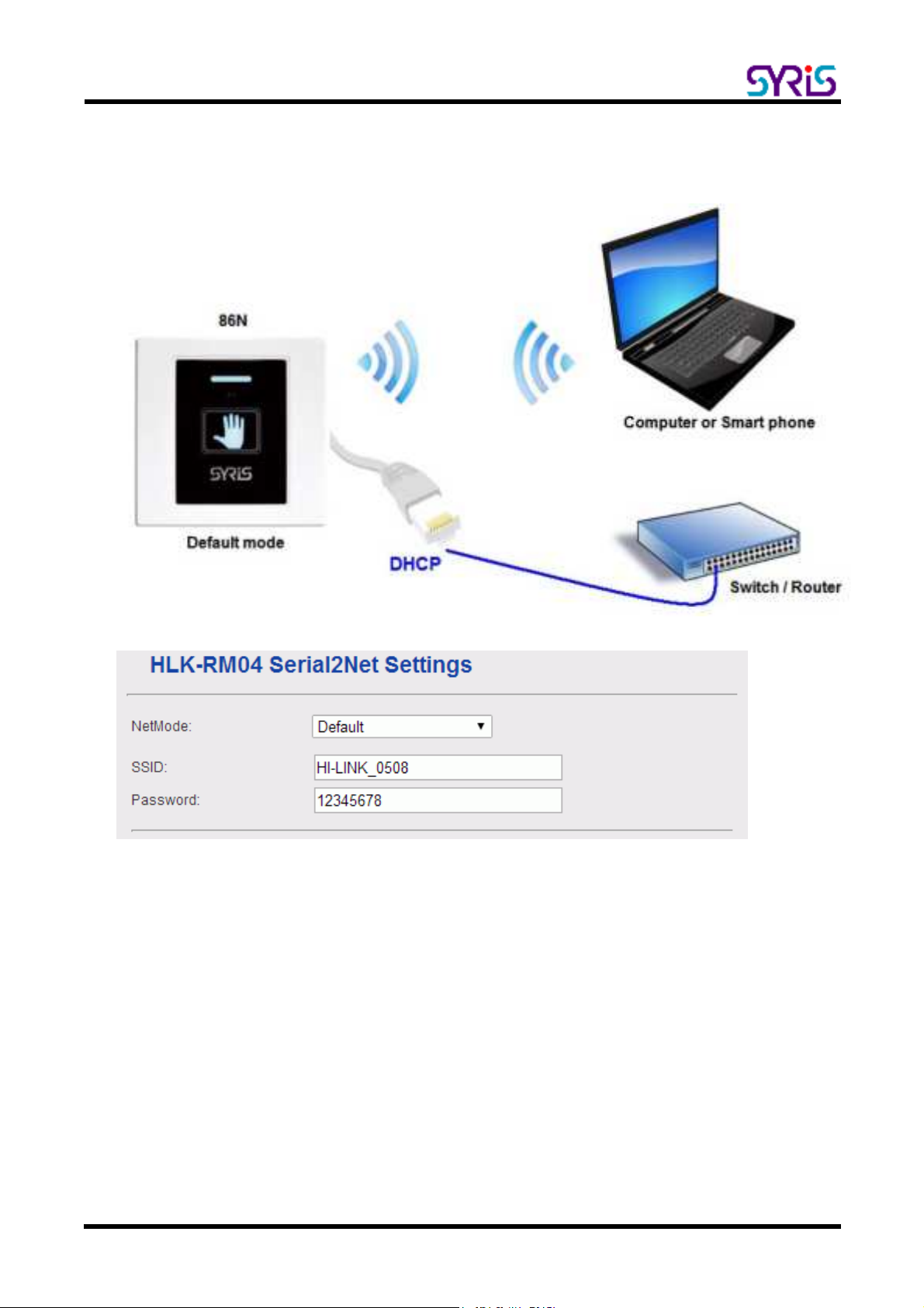
Ethernet 10/ 100 base-T Ethernet
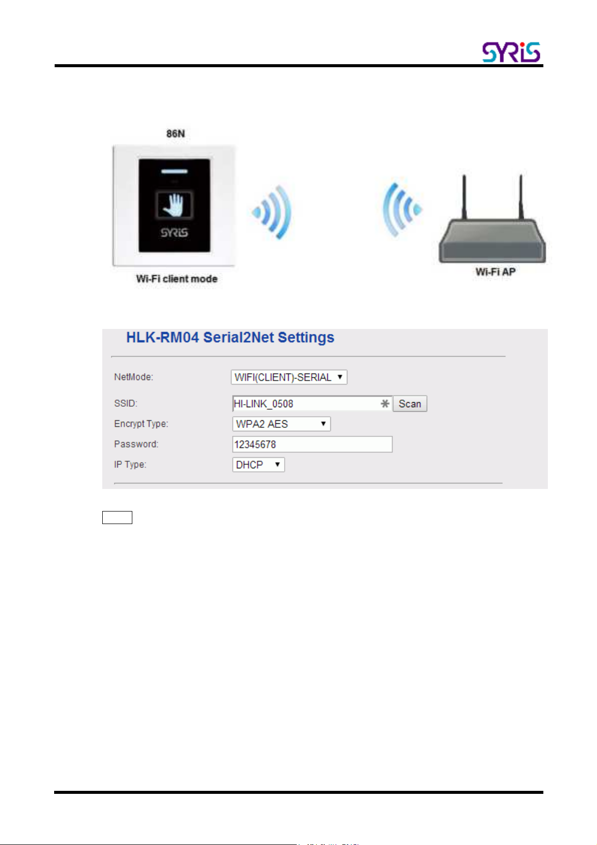
Wi-Fi 802.11 b/ g/ n
Black/ White List 500
Event Log 1180
Baud Rate 19,200 bps (4,800~ 230,400 bps)
Read Card Time 0.1 second
Keypad 1 Key (Capacitive Touch)
IR Sensor 1 I R Sensor, adjustable range 0-10 cm
Status Indicator Tricolor LED(RGB)
Touch Status I ndicator Tricolor LED(RGB)
Interface Ethernet, Wi-Fi, Wiegand, RS-485, USB
Device I D 0001~ 9999
Digital Input Up to 3 (1 no-voltage DI +2 no-voltage DI share the same port with
Wiegand)
Digital Output Up to 4 (2 Relay + 2 output share the same port with Wiegand)
Voice Output On-Board Buzzer
Operation/ Storage Temperature -10℃~+60℃ / -20℃~+70℃
Power 8V ~ 28V DC / 1W ~ 6W
Size(mm) 86(W) x 86(H) x 41.6(D) mm (No Wire I ncluded)

SYSR86N Standard TCP/IP Reader Operation Manual
2
II. Wiring Diagram

SYSR86N Standard TCP/IP Reader Operation Manual
3
III. Network Parameter Setting
1. Execute “NET_Discover_V0110.exe” and press to search SY86N series product.
2. Factory default I P is “192.168.1.101”. User can check the MAC address from product sticker with IP
to conf irm the device.

SYSR86N Standard TCP/IP Reader Operation Manual
4
3. Double click IP (192.168.1.101) to open the web configure page(http:/ / 192.168.1.101)
Default login I D / Passw ord : admin / admin

SYSR86N Standard TCP/IP Reader Operation Manual
5
4. Default Net Mode is the same as the following. User can modify Net Mode and other parameters. If
device cannot communicate properly after setting, user can reset NET module via Micro USB.
Communication Parameter Factory Default
Serial Configure 230400,8,n,1
Serial Framing Length 1050
Locale/ Remote Port Number 5001

SYSR86N Standard TCP/IP Reader Operation Manual
6
I V. Network Mode Switch
86N series device support 4 network modes: Dual mode、ETH(Ethernet)、Wi-Fi AP、Wi-Fi client.
Default Ethernet (DHCP) + Wi-Fi AP mode
ETH-SERI AL Ethernet only (Factory Default)
WI FI (CLIENT)-SERI AL Wi-Fi client mode
WI FI (AP)-SERI AL Wi-Fi AP mode
1. ETH-SERI AL:Factory default is ETH-SERI AL. ( Standard TCP/ I P Reader )
When user modify the I P and click on Apply button, device will reboot and apply the setting after 30
seconds.

SYSR86N Standard TCP/IP Reader Operation Manual
7
2. Wi-Fi client mode:86N can be set to communicate via Wireless AP without Ethernet.
SSI D: Enter the SSI D from AP you will connect to network.
Scan : User can scan AP in range of 86N and select one to connect. But user cannot scan the AP
after changing default network mode (Ethernet only) to Wi-Fi (Client). 86N need to power off / on to
enable the scan function.
Encrypt Type : Select Encrypt type for AP connection.
Passw ord: Enter password for AP.
I P Type: DHCP is default mode. I f user have to setup a static I P, please select Static.
PS: Wi-Fi MAC address is Ethernet MAC subtract 1.
Ex. Ethernet MAC : AC:A2:13:B5:5A:B5, Wi-Fi MAC : AC:A2:13:B5:5A:B4

SYSR86N Standard TCP/IP Reader Operation Manual
8
3. Wi-Fi AP mode:Setup 86N as AP(Wireless Access Point) for client device to communicate. This mode is
usually for setting device.
SSI D: Setup 86N device’s SSI D.
Encrypt Type : Select Encrypt Type for the AP.
Passw ord: Setting 86N device’s Wi-Fi password.
I P address: Setting 86N device’s Wi-Fi IP address.
Subnet Mask: Setting 86N device’s Wi-Fi subnet mask.

SYSR86N Standard TCP/IP Reader Operation Manual
9
4. Default mode:Ethernet (DHCP) + Wi-Fi AP mode.
It’s Dual-Mode ( Ethernet and Wi-Fi AP,but Ethernet only support DHCP.)
SSI D: Setup 86N device’s SSI D.
Passw ord: Setting 86N device’s Wi-Fi password.

SYSR86N Standard TCP/IP Reader Operation Manual
10
V. USB Connection
Setup 86N parameter via Micro USB.
1. I nstall USB driver ”CDC_USB_Driver_VCP_V1.4.0_Setup.exe”
2. System will generate a virtual COM port.
For example. Check port in device manager.(below picture is COM 3)
Micro USB

SYSR86N Standard TCP/IP Reader Operation Manual
11
User also can update driver manually. The driver is saved in the folder that is same as following.
3. Get device Model information and serial number by using V7 Tools with correct COM port.
4. V7 Tools also provides Ethernet mode. User only needs to fill-in correct I P and Port and click
to setup.
1 2
3 4

SYSR86N Standard TCP/IP Reader Operation Manual
12
VI . V7 Tools Tool Parameter Setting
1. Basic:
Basic: Get device serial number、device I D and f irmware version
Warm Start: Reboot 86N
Initial: Restore 86N to factory default (I t is NOT including network setting).
NET Initial (6 sec): Restore network parameter of 86N to Default mode. User has to setup by referring the
following information after restore device to factory default.
Communication Parameter Factory Default
Serial Configure 230400,8,n,1
Serial Framing Length 1050
Locale/ Remote Port Number 5001

SYSR86N Standard TCP/IP Reader Operation Manual
13
2. Reader
Set I nterface: Setup reader’s communication interface. Default is “Wiegand & RS485”.
Set Message Mode: Click on the option active to enable message mode setting. User can setup 86N
message display on panel.
Card LED: Time for read card LED ON, default is 30 x 10ms
Card Beep: Time for read card beep on, default is 30 x 10ms
I SO14443A/ B/ I SO15693 :
Same Card Delay: Setup time gap for reading the same card, default is 10 x100ms (1 second)
Green Mode: Slow down the card read speed to power saving.
Reset: Reset RF I C aft er read card.
Card Type: Choose card type to enable 86N read specif ic card.
UID(A): Read ISO14443A Card UID.
Block: Read Block data (Must disable other card type).
UID(B): Read I SO14443B Card UID.
GUID(B): Read the China second generation of resident ident if ication card.
ISO15693: Read ISO15693 Card UID
7 byte: Read 7byte format Card UID
Car d Te st : Test t h e r ea de r f u n ct i on .

SYSR86N Standard TCP/IP Reader Operation Manual
14
86 Series-Touch I R Sensor:
HF/ LF Read : Setup read card mode
Auto:Read card automatically. Users do not have to touch 86N panel or trigger I R sensor.
Touch Key:Only read card when device panel is touched. Flash card time is within 10 seconds. The LED
indicator will turns red in the period.
IR Sensor:Only read card when I R is triggered. Flash card time is within 10 seconds. The LED indicator
will turns red in the period.
Touch Key or I R Sensor:Users can flash card when device panel is touched or I R is triggered. Flash card
time is within 10 seconds. The LED indicator will turns red in the period.
Off:Turn off read card function.
Touch Key: Setup output mode when Touch Key is triggered.
I R Sensor: Setup output mode when I R is triggered.
I R Power: Setup I R sensor power. It’s related working range. (100% is farthest,10% is closest).
3. 86 Series-Bluetooth:
Bluetooth Mode : Setup receiving mode for Bluetooth signal.
Auto:Receive Bluetooth signal automatically.
IR Sensor:Receive Bluetooth signal after triggering I R sensor. I nitial time is 10 second. (the time is fixed)
Off:Turn off Bluetooth.
Bluetooth PI N: Default pin is 8888
BT3.0+ 4.0 : Setup Bluetooth working mode. Default is BT3.0+ 4.0.(Auto detect)
BT Name: Setup device Bluetooth name. Default is SYBT_(+ S/ N). I t’s the name for searching with
Bluetooth.
BT Same: Setup Bluetooth Open Door time of same card. Default is 50 (50 x 0.1= 5 second).

SYSR86N Standard TCP/IP Reader Operation Manual
15
4. 86 Series-Xtive TAG
Xtive TAG: Setup read mode for xtive RFID tag.
Key:Only receive signal from xtive RFID tag that pressed button.
Auto :Receive xtive RFID Tag signal automatically.
IR Sensor:86N only receive xtive RFI D Tag signal when IR is triggered. Start read time is about 10
seconds.
Off:Turn off the function to read Active RFID tag
Exciter I D: This parameter should use with SYRIS exciter, default values are “0” means disable. If this
function enable, reader will only receive tag’s signal which include set exciter ID.
Same: Same card time. Default is 50 (50 x 0.1= 5 second)
Gain: Set Gain (1~13) to control reader’s read range.
Level 13 is the max range (default setting), Level 1 is the shortest read range.
RSSI : Adjust RSSI level (0~250) to filter TAG which have low RSSI signal in reader.
Ex. Set RSSI Level to 120, Reader will receive tag which RSSI are stronger than 120.
5. 86 Series-DI / DO Mode
DI / DO Mode Setting- RS485 Mode ( Communication interface have to sw itch into RS485)
DO1 : Setup DO1 motion parameter
RS485:Control DO1 motion via RS485.
Touch Key:To activate DO1 by using touch panel keypad.
IRSensor:To activate DO1 by using I R sensor.
Touch Key or IR Sensor:To activate DO1 by using touch panel keypad OR IR sensor. (Default)
DI 2/ DO3 : Setup the contact mode ( DI2 or DO3 )
DI2:Setup the contact does work as DI 2 (Default)
DO3 RS485:Setup the contact does work as DO3. It is triggered via RS485.
DO3 Touch Key:The contact does work as DO3. I t is triggered by touch key.
DO3 IRSensor:The contact does work as DO3. I t is triggered by I R.
DO3 Touch Key or I R Sensor:The contact does work as DO3. It is triggered by touch key or I R.

SYSR86N Standard TCP/IP Reader Operation Manual
16
DI 3/ DO4 : Setup the contact mode ( DI3 or DO4 )
DI3:Setup the contact does work as DI 3 (Default)
DO4 RS485:Setup the contact does work as DO4. I t is triggered via RS485.
DO4 Touch Key:The contact does work as DO4. I t is triggered by touch key.
DO4 IRSensor:The contact does work as DO4. I t is triggered by I R.
DO4 Touch Key or I R Sensor:The contact does work as DO4. It is triggered by touch key or IR.
PS. DO3 and DO4 need connect extra Relay module ( MDRL02) t o w ork.
MDRL02 W D0 connects DO3( 8 6N) . MDRL02 WD1 connects DO4( 86N) .
DI / DO Mode Setting – Wiegand Mode ( Communication int erface have to sw it ch int o W iegand )
DO1 : Setup DO1 motion parameter
Touch Key:To activate DO1 by using touch panel keypad.
IRSensor:To activate DO1 by using I R sensor.
Touch Key or IR Sensor:To activate DO1 by using touch panel keypad OR IR sensor. (Default)
MESSAGE→Setup contact motion mode
LEDGI:MESSAGE contact is grounding, reader indicator green on (Default).
LEDRI:MESSAGE contact is grounding, reader indicator red on.
BEEPI :MESSAGE contact is grounding, reader buzzer on.
DO1:MESSAGE contact is grounding, reader DO1 on.
DO2:MESSAGE contact is grounding, reader DO2 on.
DO Time : DO outputs activate time
Setup activated time to each DO point. DO1、DO2 are reader Relay. DO3、DO4 are extra Relay module.
All of the default time is 50 x 0.1 sec (5 seconds).
Other manuals for SYSR86N-HBX1
1
Table of contents
Other Syris Card Reader manuals
Popular Card Reader manuals by other brands

RaidSonic
RaidSonic IB-863-B Brochure & specs

Kingston Technology
Kingston Technology MobileLite Wireless user manual

NT-ware
NT-ware uniFLOW Release Station Configuration manual

Kantech
Kantech KT-MUL-MT-KP instruction manual

Infinite Peripherals
Infinite Peripherals INFINEA BLUEPAD user manual

Davis Instruments
Davis Instruments 8105 user guide