NOTE: If any items are missing or damaged, contact the dealer immediately.
Powerful New
Experience with
Voice Dialing!
Quick Setup Guide
Wherever Business Grows
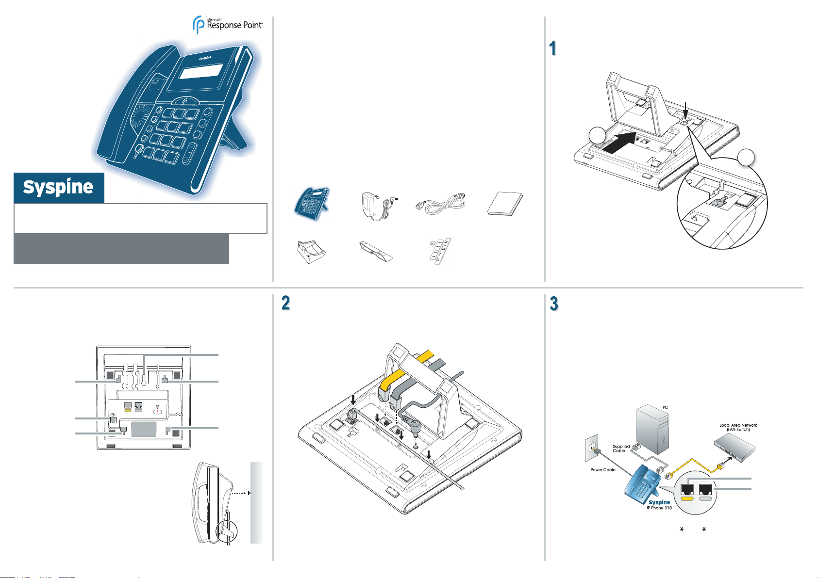
Package Contents
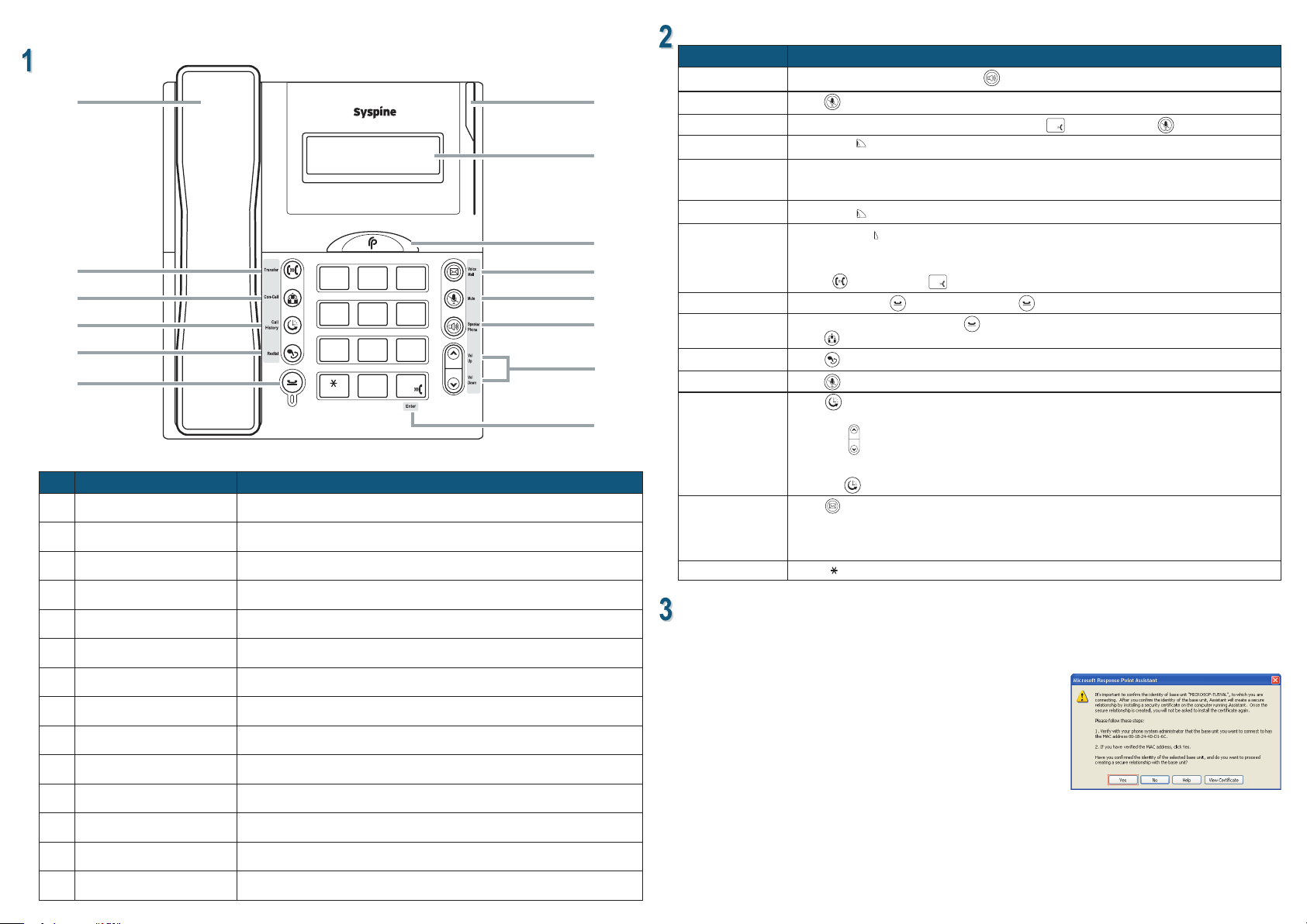
IP Phone 310, handset and
handset cable Power adaptor 2m Ethernet Cable Quick Start Guide
Desktop Phone Stand Wall Mount Stand Labels
Locating the IP Phone 310
Desktop Installation
1. Insert the two locating tabs into the sockets as shown.
2. Push the stand toward the top of the IP Phone 310 until it clicks into place.
Wall Mount Installation
For installation ease, use the following illustrations to correctly wall mount the
Syspine IP Phone 310.
NOTE: The handset hook is supplied in the upright position, suitable for desktop or
wall mounting. If the phone is installed on a desktop without the stand, remove
the hook and install it point down.
Hardware Setup
The section that follows describes how to install the Syspine IP Phone 310.
Syspine IP Phone 310
A Microsoft®Response Point™ Phone System
Important notIce: please read carefully
•Power, network or telephone service outages: If there is an outage, disruption, or other degradation
of the power, network or telephone services at your location, Response Point will not work.
•How to dial 911: Please inform all of your employees, visitors, and Response Point users that they can
either dial 911 or 9-911 to access 911 emergency services.
•Maintain an alternative means of calling 911: You should maintain a backup means of calling 911
emergency services (for example, by using a phone plugged into a standard telephone line or a cell
phone) in case of a power failure, telephone service outage, or other problem that may inhibit you from
using Response Point.
•811 feature: By dialing 811, you can call back the last phone that was used to dial 911. This information
will be stored for only 24-48 hours after 911 is dialed. NOTE: this feature may not work if the phone has
not been registered with the Response Point base unit by your system administrator.
•911 location obligations that may apply to certain owners of Response Point: Your telephone
company may be required under applicable law to provide a telephone number and address associated
with that telephone number to emergency services when a caller dials 911. Please note that certain
U.S. (state and/or federal) and foreign laws may require the owner of a multi-line telephone system
(MLTS), such as Response Point, to provide emergency services with the physical location/address of
the phone that was used to call 911, in addition to the caller telephone number. Compliance with such
MLTS laws is your responsibility as the owner of Response Point. Response Point does not provide to
emergency services the physical location/address of a phone that is used to call 911.
Basic connections
Locate the rear view of the IP Phone 310 and make all the necessary connections
as follows.
Connecting the IP Phone 310
The IP Phone 310 supports daisy-chain connection for limited port access,
eliminating the need for extra Ethernet cables.
If port access is not a consideration and a daisy chain connection is not required,
attach the IP Phone 310 directly to the LAN switch with the supplied cable. Otherwise,
perform the following steps to connect the IP Phone 310 as part of a daisy-chain:
1. Disconnect the LAN cable from the PC and plug it into the LAN port on the
IP Phone 310.
2. Using the supplied Ethernet cable, connect the PC port on the IP Phone 310 to the
LAN port on the PC.
3. Using the supplied power cables for each phone, connect the IP Phones to a power
source.
4. Record the IP address for each phone as displayed on the LCD screen.
Important: The Syspine IP Phone 310 is designed specically to work in conjunction with the
Syspine Digital Operator System A50.
Connect to LAN
Connect to PC
Connect to power outlet
Connect to phone
handset
Connect to LAN
Connect
to PC
1. Insert the two stand locating tabs in to the sockets on
the phone.
2. Push the stand toward the bottom of the IP Phone 310
to until it clicks into place.
3. Locate a clean, even wall space with adequate room
for cabling.
4. Drill a hole and insert a suitable wall-xing plug.
5. Insert a suitable screw and tighten until approximately
5 mm (0.2 inch) is visible.
6. Align the wall-mounting slot on the underside of the
IP Phone 310 with the screw.
7. Place the IP Phone 310 on the wall and pull down to
locate the screw securely.
Desktop stand
socket
Handset
connection port
Wall mount
stand socket
Wall mount
socket
Desktop stand
socket
Wall mount
stand socket
NOTE: If the IP address is not displayed, enter # 47# (# IP#) on the keypad to display the IP
address.
NOTE: If the IP Phone 310 is connected through a PoE device, it is not necessary to
connect the power adapter.
TM