manuals.online logo
Brands
  1. Home
  2. •
  3. Brands
  4. •
  5. System Sensor
  6. •
  7. Switch
  8. •
  9. System Sensor Zonecheck Keyswitch ZCK-1 User manual

System Sensor Zonecheck Keyswitch ZCK-1 User manual

D770-31-00 1 I56-1610-001
©2000 System Sensor
Zonecheck Keyswitch
ZCK-1, ZCK-1E
INSTALLATION AND MAINTENANCE INSTRUCTIONS
A Division of Pittway
3825 Ohio Avenue, St. Charles, Illinois 60174
1-800-SENSOR2, FAX: 630-377-6495
www.systemsensor.com
Electrical Specifications
Key Switch Operating Voltage ZCK-1: 110V, 60 Hz; ZCK-1E: 220V, 50 Hz
Key Switch Mounting Options Includes back box for surface or flush mounting.
For pre-wiring, use a 4-11/16” x 4-11/16” back box
Key Switch Operation Modes Self-test: Wired locally
Group test: Interconnected
Key Switch LED Operation Ready state: No LED
Test initiation: Green LED
Flow switch activation: Red LED
WIRING DIAGRAM FOR STAND ALONE APPLICATION
}
}
FOR INTERCONNECTING MULTIPLE ZONECHECK UNITS
}
}
}
}
AC POWER AND PUMP WIRING
MUST CONFORM TO NEC OR
YOUR LOCAL CODES.
OR OTHER MONITORING DEVICE.
WATERFLOW
DETECTOR
KEYSWITCH OPERATION IF WATERFLOW
DETECTOR IS CONNECTED TO PANEL
WF INPUT NOT REQUIRED FOR
NOTE:
AC GROUND
AC POWER
GND
JUNCTION BOX
AC
PUMP
PUMP
AC
WF INPUT
WATERFLOW
DETECTOR
INTER-CONNECT
PUMP
TO EARTH GND.
OR ATTACH TO
JUNCTION BOX
OR ATTACH TO
JUNCTION BOX
OR ATTACH TO
INTERCONNECT
SWITCH FOR
ZONECHECK
TO NEXT
AC GROUND
AC POWER
GND
AC
PUMP
PUMP
AC
TO EARTH GND.
PUMP
WF INPUT
INTER-CONNECT
PUMP
AC POWER
AC GROUND
TO EARTH GND.
PUMP
PUMP
AC
AC
GND
INTER-CONNECT
WF INPUT
WATERFLOW
DETECTOR
D770-31-00 2 I56-1610-001
©2000 System Sensor
Three-Year Limited Warranty
System Sensor warrants its enclosed keyswitch to be free from defects in
materials and workmanship under normal use and service for a period of
three years from date of manufacture. System Sensor makes no other ex-
press warranty for this keyswitch. No agent, representative, dealer, or em-
ployee of the Company has the authority to increase or alter the
obligations or limitations of this Warranty. The Company’s obligation of
this Warranty shall be limited to the repair or replacement of any part of
the keyswitch which is found to be defective in materials or workmanship
under normal use and service during the three year period commencing
with the date of manufacture. After phoning System Sensor’s toll free
number 800-SENSOR2 (736-7672) for a Return Authorization number,
send defective units postage prepaid to: System Sensor, Repair Depart-
ment, RA #__________, 3825 Ohio Avenue, St. Charles, IL 60174. Please
include a note describing the malfunction and suspected cause of failure.
The Company shall not be obligated to repair or replace units which are
found to be defective because of damage, unreasonable use, modifica-
tions, or alterations occurring after the date of manufacture. In no case
shall the Company be liable for any consequential or incidental damages
for breach of this or any other Warranty, expressed or implied whatsoever,
even if the loss or damage is caused by the Company’s negligence or fault.
Some states do not allow the exclusion or limitation of incidental or conse-
quential damages, so the above limitation or exclusion may not apply to
you. This Warranty gives you specific legal rights, and you may also have
other rights which vary from state to state.
Please refer to insert for the Limitations of Fire Alarm Systems
Pre-Operation Guidelines
Contact central monitoring station or appropriate fire safety
personnel prior to testing Zonecheck.
Zonecheck Testing: Self-Test Mode
To activate the Zonecheck wired locally to the ZCK-1 key
switch insert key and turn to the right. The green LED on
the ZCK-1 will illuminate to show that the pump has been
activated. The red LED on the ZCK-1 will illuminate once
the waterflow detector has been activated.
Note: The red LED will not illuminate if the waterflow
detector is not wired to the ZCK-1 key switch.
When testing has been completed, turn the key
back to the standby position.
WARNING
Only activate the Zonecheck ZCK-1 key switch when the
valves are opened and the sprinkler system is full.
Zonecheck Testing: Group-Test Mode
All Zonecheck systems whose ZCK-1 key switches are inter-
connected (refer to interconnecting wiring diagram), may
be activated from any ZCK-1 key switch. To initiate the
group test, insert key and turn to the left.
The LEDs on the key switch from where the group test was
initiated, only indicate the activity for the Zonecheck con-
nected directly to that key switch.
When testing has been completed, turn the key back to the
standby position.
This manual suits for next models

1

Other System Sensor Switch manuals

System Sensor EPS40EXP User manual

System Sensor

System Sensor EPS40EXP User manual

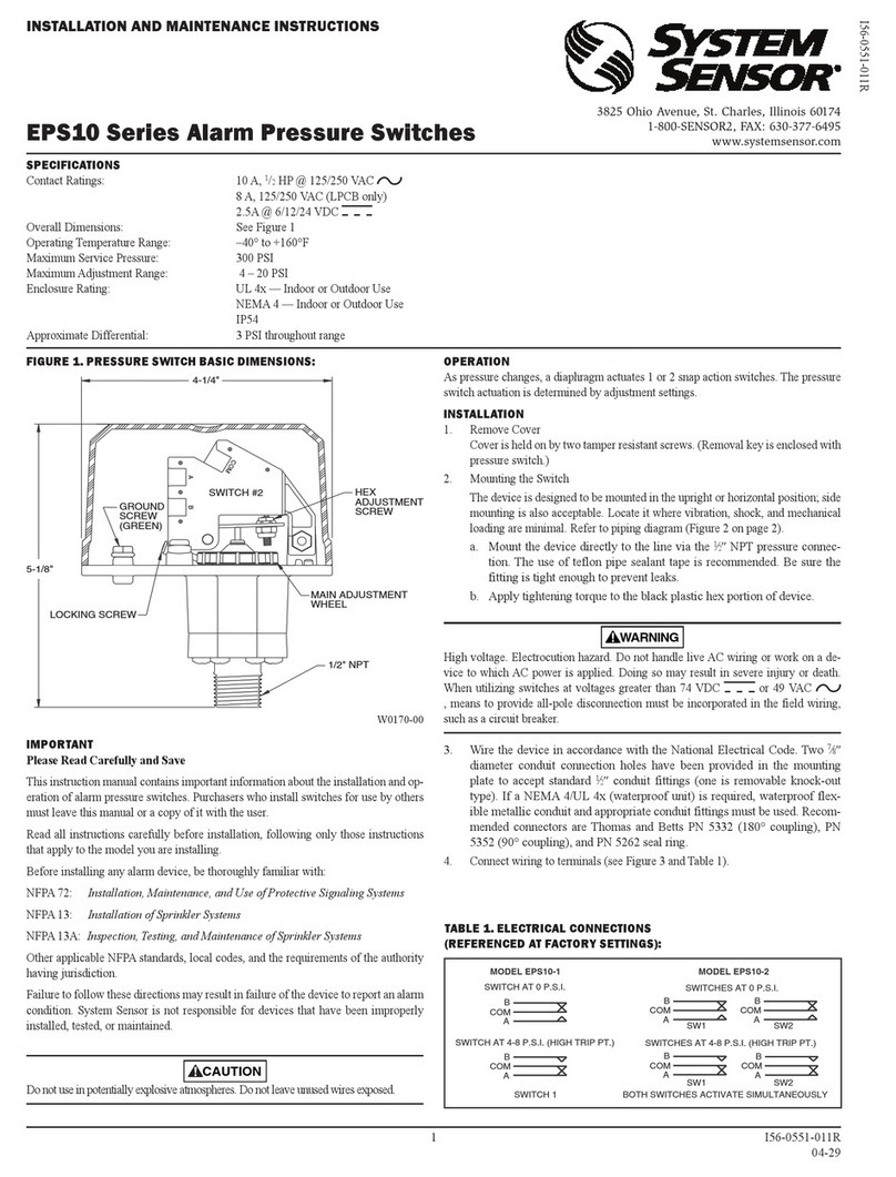
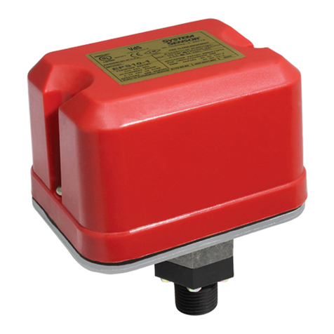
System Sensor EPS10 Series User manual

System Sensor

System Sensor EPS10 Series User manual

System Sensor PSP1 User manual

System Sensor

System Sensor PSP1 User manual

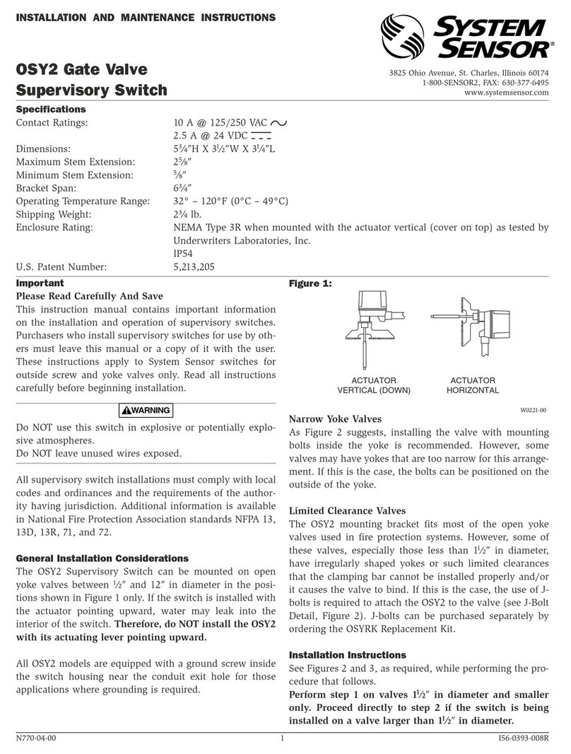
System Sensor OSY2 User manual

System Sensor

System Sensor OSY2 User manual

System Sensor EPS40 Series User manual

System Sensor

System Sensor EPS40 Series User manual

System Sensor OSY2 User manual

System Sensor

System Sensor OSY2 User manual

System Sensor PSP1 User manual

System Sensor

System Sensor PSP1 User manual

System Sensor EPS10 Series User manual

System Sensor

System Sensor EPS10 Series User manual

System Sensor EPS10 Series User manual

System Sensor

System Sensor EPS10 Series User manual

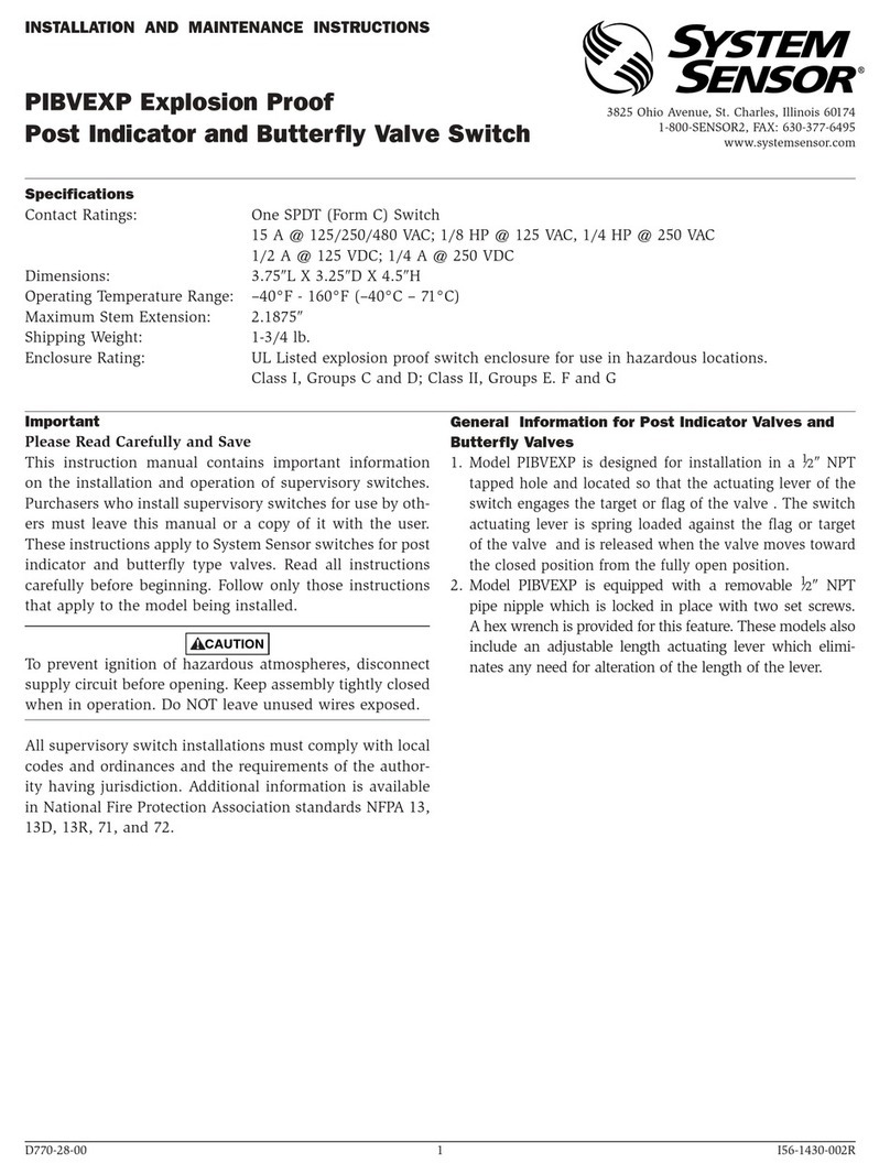
System Sensor PIBVEXP User manual

System Sensor

System Sensor PIBVEXP User manual

System Sensor EPS40 Series User manual

System Sensor

System Sensor EPS40 Series User manual

Popular Switch manuals by other brands

Uni-Fi USW-24-POE quick start guide

Uni-Fi

Uni-Fi USW-24-POE quick start guide

MyCableMart CE-HSWUH0201S user manual

MyCableMart

MyCableMart CE-HSWUH0201S user manual

Planet IGS-4215-4P4T Quick installation guide

Planet

Planet IGS-4215-4P4T Quick installation guide

8 Level FES-5D Installation guidelines

8 Level

8 Level FES-5D Installation guidelines

IR-Tec WallSenzr BBS-702 series installation instructions

IR-Tec

IR-Tec WallSenzr BBS-702 series installation instructions

MyCableMart CE-HSWUH0501S user manual

MyCableMart

MyCableMart CE-HSWUH0501S user manual

Little Giant RS-5 owner's manual

Little Giant

Little Giant RS-5 owner's manual

UseTECH FlowTimer+ operating manual

UseTECH

UseTECH FlowTimer+ operating manual

Black Box SW1020A manual

Black Box

Black Box SW1020A manual

Planet XGS-6350-12X8TR Quick installation guide

Planet

Planet XGS-6350-12X8TR Quick installation guide

Qlogic SANbox 5000 Series quick start guide

Qlogic

Qlogic SANbox 5000 Series quick start guide

Uni-Com SmartGST-801M Specifications

Uni-Com

Uni-Com SmartGST-801M Specifications

AirLive LIVE-GSH5T user manual

AirLive

AirLive LIVE-GSH5T user manual

C.P. Electronics ALC15 installation guide

C.P. Electronics

C.P. Electronics ALC15 installation guide

Ruby Tech GS-5124C Technical specifications

Ruby Tech

Ruby Tech GS-5124C Technical specifications

Speed Link SNAPPY user guide

Speed Link

Speed Link SNAPPY user guide

Tripp Lite U223-007-IND owner's manual

Tripp Lite

Tripp Lite U223-007-IND owner's manual

Qlogic SANbox 5000 Series installation guide

Qlogic

Qlogic SANbox 5000 Series installation guide

manuals.online logo
manuals.online logoBrands
  • About & Mission
  • Contact us
  • Privacy Policy
  • Terms and Conditions

Copyright 2025 Manuals.Online. All Rights Reserved.