Systems Trading Corporation GZ3D User manual

of 241
www.stcny.com
Systems Trading Corporation
450 7th Avenue Suite 2809, New York, NY 10123
Customer service: (877)782 4482
7’1” 9’4.7”
10’7”
10’7”
11’4.6”
11’4.6”
Assembly Instructions
Instrucciones de ensamblaje
Gazebo GZ3D
Aluminium Composite Roof Panels
Paneles de Techo de Aluminio Compuesto
5

of 242
www.stcny.com
Introduction
Thank you for purchasing the Gazebo GZ3D.
When properly assembled and maintained, this gazebo will provide many years of enjoyment!
These instructions include helpful hints and important information needed to safely assemble and properly
maintain the gazebo. Please read these instructions completely before you begin.
Our patented gazebo has been designed for easy assembly. All steps can be completed by a team of
four people. The assembly should take about two hours.
Before Starting Assembly:
CAREFULLY READ ALL THE INSTRUCTIONS BEFORE YOU BEGIN AND FOLLOW THE
STEPS IN THE ORDER THEY ARE PRESENTED.
1.Make sure you have all the necessary parts:
Compare the contents of the three cartons to the List of Parts. If any parts are missing or damaged, or
you have any questions, please contact Customer service: (877)782 4482 before beginning assembly.
2.Lay the parts out in separate staging areas:
The List of Parts has the corresponding step number referenced to each part. We recommend that
while you go through the list, make staging areas for each step and place the parts necessary for
each step in these areas. This will save you time and effort during assembly.
3.Select a Location:
When selecting a location for your gazebo, a flat level area is essential and if possible with proper
water drainage and easy access to power and water, if neccessary.
Choose a sunny, level position away from overhanging trees and power lines and protected from the
wind as much as possible. Locate underground pipes or cables before preparing the site or anchoring
the gazebo.
Note: You may assemble the gazebo on a hard level surface and move it to its final location when
finished. Make sure that there are no obstacles between the assembly area and the final position.
4. Prepare a Foundation:
After choosing a location, proper preparation of the site is recommended. The site must be level.
If the site is not level, create a base slightly larger than the outside dimensions of the gazebo using a
perimeter of two by fours filled with either soil, sod or gravel.
Make sure the base is square by measuring the diagonals from both directions and making sure
they are equal. The gazebo is secured with pegs into holes cast with concrete.
If you decide to have a concrete base, it is best to contact a reliable contractor to make sure it is flat
and level. Make sure you have checked with your local authorities regarding any required building
permits.
5. Make sure you have the proper tools:
• Tape Measure • 2 Small Step Ladders
• Work Gloves • Wooden Mallet
• Safety goggles • Scissors
• Phillips Screwdriver • Liquid soap or WD40 Lubricant
• Spirit Level • Hex Key (included)
NOTE: A cordless drill with Phillips head bit is highly recommended but not essential.

of 243
www.stcny.com
Introducción
Les agradecemos el haber adquirido el Gazebo GZ3D.
Al ser ensamblado y mantenido correctamente, disfrutarán del gazebo por muchos años.
Estas instrucciones incluyen consejos útiles e información importante y necesaria para ensamblar de modo segu-
ro y mantener de forma correcta el gazebo. Por favor lean estas instrucciones en su totalidad antes de empezar.
Nuestro gazebo patentado ha sido diseñado para un fácil ensamblado. Todos los pasos se pueden llevar a cabo
por un equipo de 4 personas. El ensamblaje debe tomar aproximadamente dos horas.
Antes de empezar el ensamblaje:
LEA CUIDADOSAMENTE TODAS LAS INTRUCCIONES ANTES DE EMPEZAR Y SIGA LOS PASOS
EN EL ORDEN QUE SON PRESENTADOS.
1. Asegúrese de tener todas las partes necesarias:
Compare el contenido de los tres cartones con la Lista de Partes. Si alguna parte falta o está dañada, o
si tiene alguna pregunta, por favor contacte a nuestro Servicio al Cliente: (877) 7824482 antes de empezar
el ensamblaje.
2. Coloque las piezas en zonas de preparación separadas:
La lista de piezas tiene el número de Paso correspondiente a cada pieza. Recomendamos que mientras usted
examina la lista, haga zonas de preparación para cada Paso y ponga las piezas necesarias para cada paso
en estas zonas.
3. Seleccione una ubicación:
Al seleccionar una ubicación para su gazebo, es esencial que sea un área plana y de ser posible con un dre
naje de agua adecuado y fácil acceso a energía y agua, de ser necesario.
Elija un lugar soleado, lejos de árboles colgantes y líneas eléctricas y protegido del viento tanto como sea
posible. Localice tuberías subterráneas o cables antes de preparar el sitio o el anclaje del gazebo.
Nota: Puede ensamblar el gazebo en una supercie dura nivelada y al terminarlo moverlo a su destino nal.
Asegúrese que no haya obstáculos entre el área de ensamblaje y la ubicación nal.
4. Prepare una base:
Luego de elegir la ubicación, se recomienda una correcta preparación del lugar. El lugar debe ser nivelado.
Si el lugar no está nivelado, haga una base ligeramente más grande que las dimensiones exteriores del gazebo
usando un perímetro de dos por cuatro relleno de tierra, césped o grava.
Asegúrese que la base es cuadrada midiendo las diagonales en ambas direcciones y asegurándose que son
iguales. El gazebo se asegura con clavijas en agujeros fundidos con concreto.
Si decide tener una base de concreto, es preferible contratar a un contratista conable para asegurarse que sea
plano y nivelado. Asegúrese de haber chequeado con las autoridades locales en relación a permisos requeridos
para construcción.
5. Asegúrese que tiene las herramientas correctas:.
• Cinta de medición • 2 Pequeñas escaleras de mano
• Guantes de trabajo • Mazo de madera
• Gafas de seguridad • Tijeras
• Desentornillador Phillips • Jabón liquido Lubricante WD40
• Nivel de aire • Llave hexagonal (incluida)
NOTE: Un taladro inalámbrico con cabeza Phillips es muy recomendable pero no esencial.

of 244
www.stcny.com
1
1
1
2
3
4
6
7
8
5
Safety Advice
• The gazebo must be positioned and xed on a at level surface.
• Dispose of all plastic bags safely. Keep them out of the reach of children.
• Keep children and pets away from the assembly area until the work is
completed.
• Always wear shoes, gloves and safety goggles when working.
• Take special care not to touch overhead power lines with the alumini-
um proles.
• Do not attempt to assemble the gazebo in windy or wet conditions.
• Do not position your gazebo in an area exposed to excessive wind.
• If using power tools or a ladder, always follow the manufacturers safety
instructions.
• Hot items such as recently used grills, blowtorches etc. must not be
stored in the gazebo.
• Make sure the gazebo complies with local building codes.
Consejos de seguridad
• El gazebo debe ser posicionado y jado en una supercie plana y nivelada.
• Deshágase de todas las bolsas plásticas de forma segura. Manténganlas fuera
del alcance de los niños.
• Mantenga alejados del área de ensamblaje niños y mascotas hasta que el trabajo
haya sido terminado.
• Siempre calce zapatos, guantes y gafas de seguridad al trabajar.
• Preste especial cuidado en no tocar líneas de energía aéreas con los perles de
aluminio.
• No trate de ensamblar el gazebo en condiciones de viento o mojadas.
• No coloque su gazebo en un áreaal viento excesivo.
• Si usa herramientas eléctricas o una escalera, siempre siga las instrucciones de
seguridad del fabricante.
• Objetos calientes, como una parrilla recién usada, sopletes, etc., no deben alma-
cenarse en el gazebo.
• Asegúrese de que el gazebo cumple con los códigos de construcción locales.
Table of Contents
I
ntroduction................................................................ 2
Table of Contents...................................................... 3
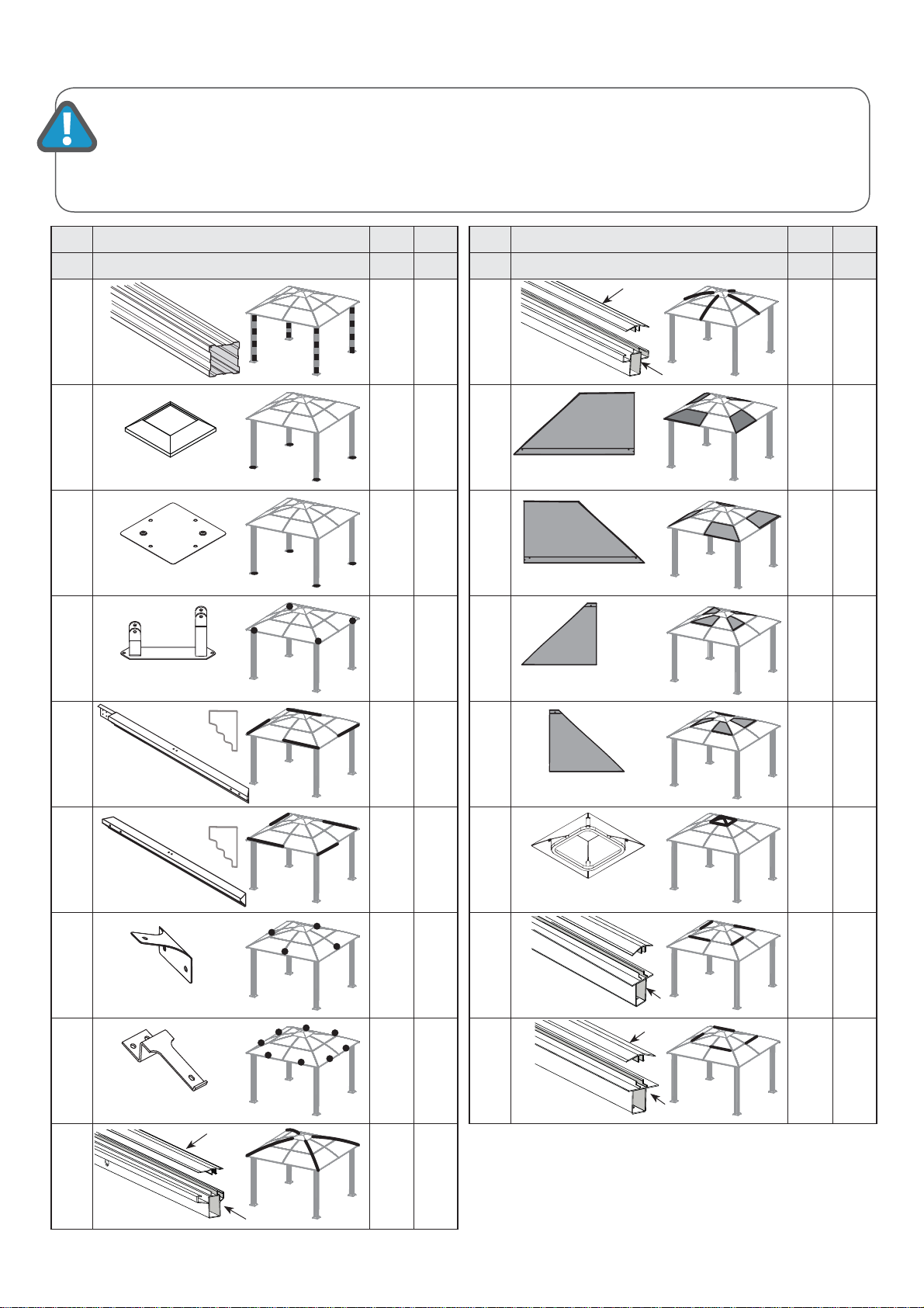
List of Parts.................................................................. 5
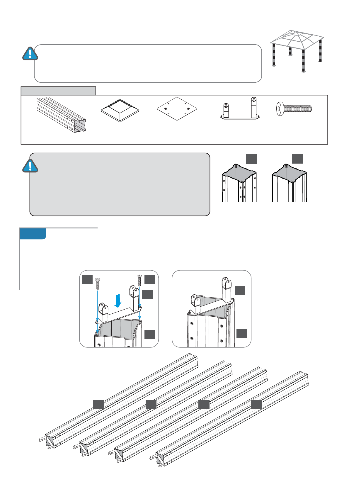
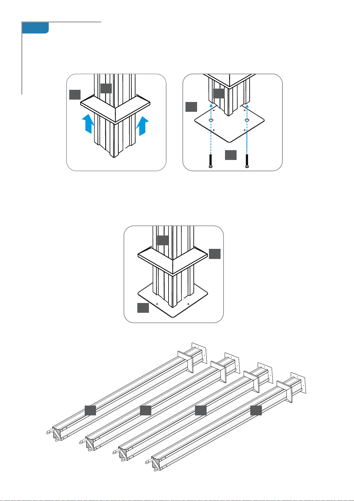
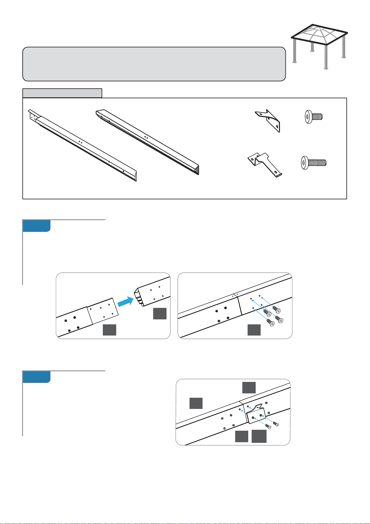
Step 1 Assembling the Corner Proles.................. 7
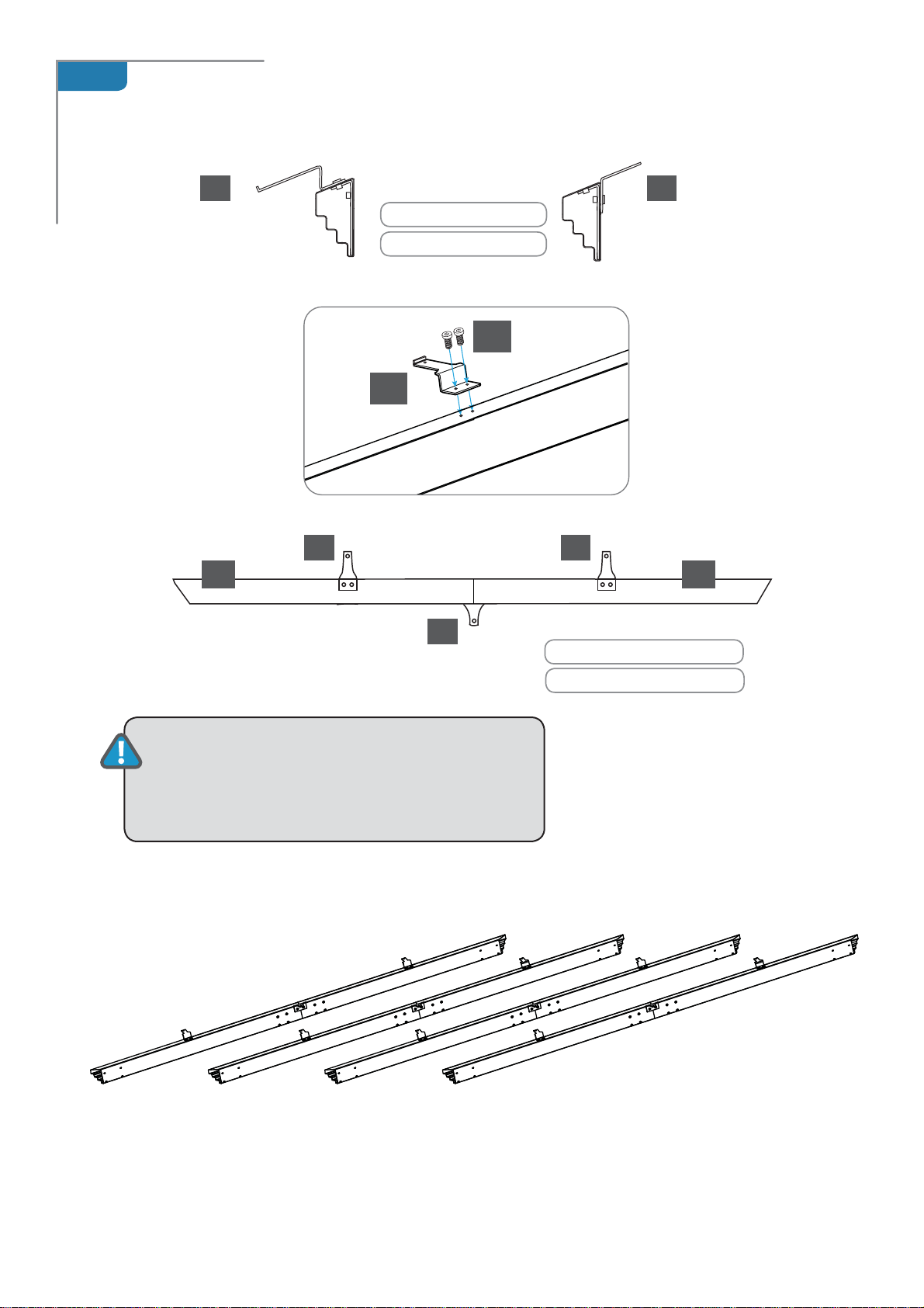
Step 2 Assembling the Rails........................................ 9
Step 3
Attaching the Rails to the Corner Prole
s...11
Step 4 Securing the Gazebo to the ground......... 13
Step 5 Installing the Lower Roof gable Proles.. 14
Step 6
Installing the Lower Horizontal Roof Proles
. 17
Step 7 Installing the Roof Panels and
Upper Roof Proles.......................................... 18
Step 8 Installing the Plastic Caps......................... 23
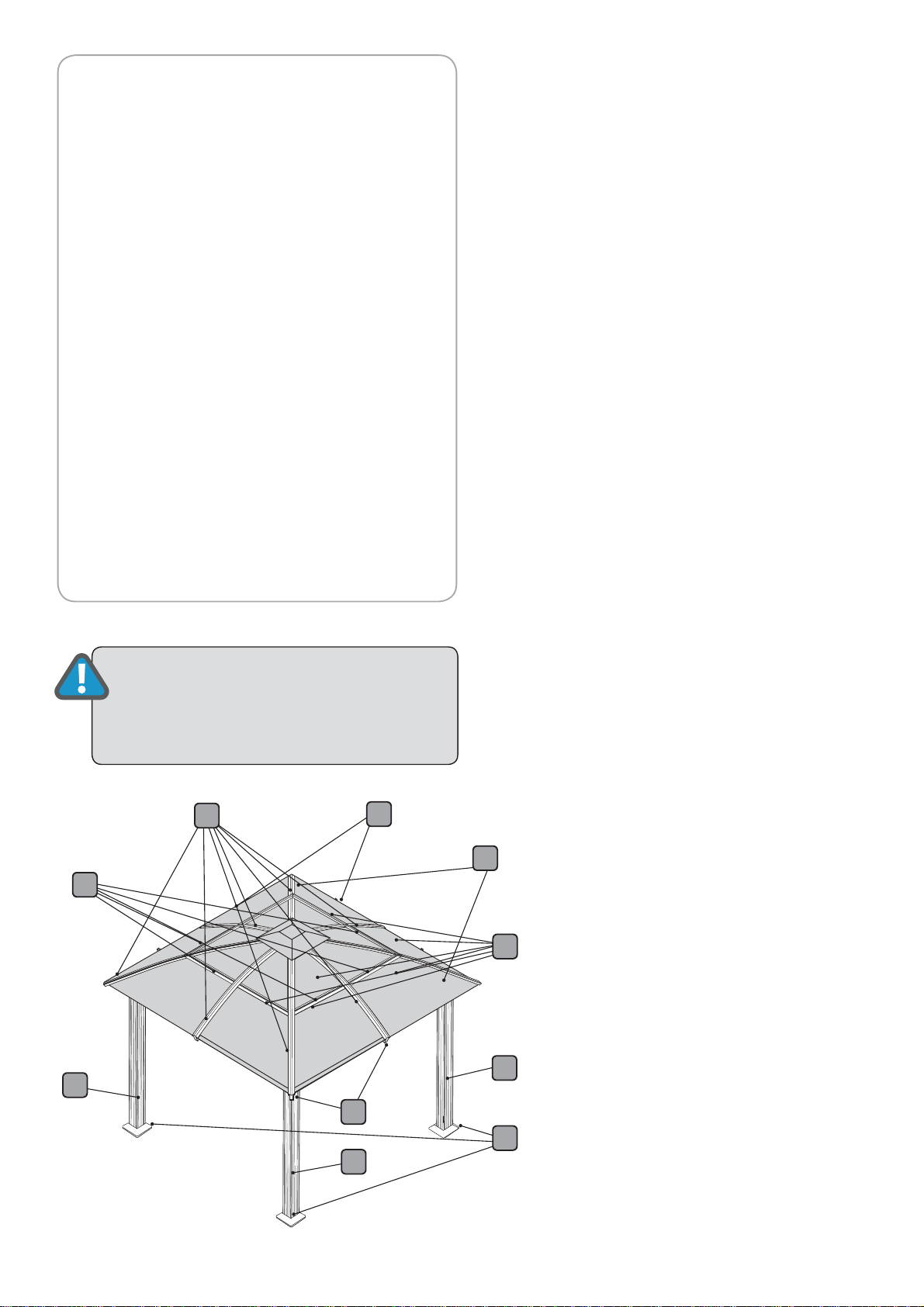
General Order of Assembly
Step 1: Assembling the Corner proles
Step 2: Assembling the Rails
Step 3: Attaching the Rails to the Corner Proles
Step 4: Securing the gazebo to the ground
Step 5: Installing the Lower Roof Gable Proles
Step 6:
Installing the Lower Horizontal Roof Proles
Step 7: Installing the Roof Panels and
Upper Roof Proles
Step 8:
Installing the Plastic Caps
ATTENTION:
DO NOT ATTEMPT TO
ASSEMBLE THE GAZEBO
ALONE!
ATENCION:
NO INTENTE ENSAMBLAR EL GAZEBO SOLO!
Tabla de contenidos
Introducción.................................................................................. 3
Tabla de contenidos ................................................................... 3
Lista de Partes................................................................................ 5
Paso 1 Ensamblaje de los perles de esquina........... ....... 7
Paso 2 Ensamblaje de los rieles............................................. 9
Paso 3 Juntando los rieles a los perles de esquina...... 11
Paso 4 Asegurando el Gazebo al suelo.............................. 13
Paso 5
Instalando los perles inferiores del techo a dos aguas
14
Paso 6
Instalando los perles inferiores horizontales del techo
17
Paso 7 Instalando los paneles del techo y los perles
del techo superior ........................................... ............... 18
Paso 8 Instalando los tapones de plástico......................... 23
Orden general de ensamble
Paso 1: Ensamblaje de los perles de esquina
Paso 2 : Ensamblaje de los rieles
Paso 3: Juntando los rieles a los perles de esquina
Paso 4: Asegurando el Gazebo al suelo
Paso 5: Instalando los perles inferiores del techo a
dos aguas
Paso 6: Instalando los perles inferiores horizontales
del techo
Paso 7 : Instalando los paneles del techo y los perles
del techo superior
Paso 8: Instalando los tapones de plástico

of 245
www.stcny.com
No. Prole Qty
Step
Núm.
Descripción Ctd.
Paso
10A
10
4
4
5,7
11
4
7
12
4
7
13 4
7
14 4
7
15 1
5
16A
16
4
4
6,7
17A
17
4
4
6,7
No. Prole Qty
Step
Núm.
Descripción Ctd.
Paso
14
1
24
1
34
1
44
1
54
2
64
2
74
2
88
2
9A
9
4
4
5,7
1808mm
1633mm
Corner
Prole
Support Frame
Support Plate
Corner Roof Connector
Rail
Rail
Outer Roof Connector
Roof
Gable Prole
Roof
Gable Prole
9A
2107mm
9
2175mm
Inner Roof Connector
Horizontal
Roof Prole
Horizontal
Roof Prole
Aluminium Composite Roof Panel
1562mm
black side
lado negro
black side
lado negro
black side
lado negro
black side
lado negro
Roof Top Cover
The gazebo is shipped in three cartons. These cartons are heavy. Be careful when lifting them.
Wear proper safety gear including work shoes, gloves and goggles. The parts are identied by removable stickers. Place all the parts for
each step in staging areas, checking that you have all parts as you go. If any parts are missing or damaged, contact STC customer service
List of Parts - Lista de Partes
El gazebo es enviado en tres cajas de cartón. Estas cajas son pesadas. Tenga cuidado al levantarlas. Use un equipo de seguridad adecuado incluyendo zapatos de
trabajo, guantes y gafas. Las partes están identicadas con etiquetas removibles. Ponga todas las piezas para cada paso en las zonas de preparación, revisando
que tenga todas las piezas a medida que avanza. Si cualquier parte falta o esta dañad, por favor póngase en contacto con servicio al cliente STC antes de empezar
Perl de
esquina
Marco de soporte
Placa de soporte
Conector de esquina del techo
16
16A
17
998mm
1008mm
1008mm
998mm
17A
10A
1537mm
10
Riel
Riel
Conector interior del techo
Conector exterior del techo
Perl de
techo a dos aguas
Perl de
techo a dos aguas
Panel de techo de Aluminio compuesto
Cubierta del techo superior
Perl de Techo horizontal

of 246
www.stcny.com
We included some extra screws and bolts for your convenience.
Screw ø 4*8
Tornillo ø 4*8
T- connector A
T- connector B
Screw M6*8
Screw M6*18
Screw M6*12
Screw M6*25
Screw M6*38
Plastic Cap #1
Plastic Cap #2
Nut M6
Plastic Cap #3
Ground Spike
Concrete Bolt
Spanner
Magnetic Hex Key
No. Profile Qty
Step
Núm.
Descripción Ctd.
Paso
28 16
4
29
16
4
30 1
31 1
32 4
6
33 4
6
34 8
5
No. Profile Qty
Step
Núm.
Descripción Ctd.
Paso
18 16
19 16
20 100
21 16
22 64
23 8
6,7
24 8
25 32
6,7
26 4
8
27 4
8
Roof top connector
Tornillo M6*8
Tornillo M6*12
Tornillo M6*18
Tornillo M6*25
Tornillo M6*38
Tapa plástica #1
Tapa plástica #2
Tuerca M6
Tapa plástica #3
Estaca
Perno de concreto
Llave
Llave hexagonal magnética
Conector- T A
Conector- T B
Incluimos unos tornillos y pernos adicionales para su conveniencia
Conector
superior del techo

of 247
www.stcny.com
1 1 1 1
11
4
21 21
4
x 4
1.A
11
Assembling the Corner Proles
Place all the parts on a level surface
.
Make sure the pieces are in the correct positions before
assembling.
Carefully follow the order of assembly to ensure an easy installation. Wear proper
safety gear including work shoes, gloves and goggles.
STEP 1
Components / Componentes
Corner prole (1)
Perl de esquina
(1)
x 4
Support plate (3)
Placa de soporte (3)
x 4
Roof connector (4)
Conector de esquina del techo (4)
x 4
Support frame (2)
Marco de soporte (2)
x 4
Screw (21)
Tornillo (21)
x 16
Place corner proles (1) parallel to each other the ground. Attach one roof connector (4) to each top
end as shown and fasten with screws (21).
ATTENTION:
The corner prole (1) has two screw holes to connect it to
the roof connector (4) and 8 pre-drilled screw holes to attach rails (5,6)
in step 3 at its top end. It has two screw holes to connect it to the sup-
port plate (3) at its bottom end.
Top end Bottom end
Ensamblando los perles de esquinas
Ponga todas las piezas en una supercie nivelada. Asegúrese que las piezas están en las posiciones
correctas antes de ensamblar. Siga cuidadosamente el orden de ensamblaje para asegurar una fácil
instalación. Use un equipo de seguridad adecuado incluyendo zapatos de trabajo, guantes y gafas.
Extremo superior Extremo inferior
ATENCION:
El perl de esquina (1) tiene dos oricios de tornillo para conec-
tarlo con el conector de techo (4) y 8 oricios de tornillo pre-perforados para
unir los rieles (5,6) en el paso 3 a su extremo superior. Tiene dos oricios de
tornillo para conectarlo a la placa de soporte (3) en su extremo inferior.
Coloque los perles de esquina (1) paralelos entre sí en el suelo. Adjunte un conector de techo (4) a cada
extremo superior como se muestra y sujete con tornillos (21).

of 248
www.stcny.com
3
21
1
21
1 1 1 1
3
2
1
x 4
1.B
Slide support frames (2) over lower end of corner proles (1).
Attach support plates (3) to corner proles as shown, using two screws (21) for each plate.
Leave support frames (2) about 10”over lower end of corner proles (1) until step 4 (
Securing the
gazebo to the ground)
Deje los marcos de soporte (2) a unas 10” sobre el extremo inferior de los perles de esquina (1) hasta el paso 4
(Asegurando el gazebo al suelo)
Deslice los marcos de soporte (2) sobre el extremo inferior de los perles de esquina (1). Adjunte las placas
de soporte (3) a los perles de esquina como se muestra, usando dos tornillos (21) para cada placa.

of 249
www.stcny.com
5
5
6
6
7
18
20
2.A
2.B
Assembling the Rails
Insert connecting part of rail (5) into blunt end of rail (6) as shown. Attach with four screws (18).
Repeat to create four sets of rails.
STEP 2
Rail (5)
Riel (5)
x 4
Rail (6)
Riel (5)
x 4
Screw (20)
Tornillo (20)
x 24
Screw (18)
Tornillo (18)
x 16
NOTE:
The Rails (5) have a preassembled connecting parts to be inserted into Rails (6).
Attach inner roof connector (7) to each
rail set as shown, using two screws (20).
Inner Roof Connector (7)
Conector interior del techo (7)
x 4
Outer Roof Connector (8)
Conector exterior del techo(8)
x 8
Ensamblando los rieles
NOTA: El Riel Largo (5) tien una parte conectora preensamblada para ser insertada dentro
del Riel (6)).
Components / Componentes
Inserte la parte conectora del riel (5) dentro del extremo romo del riel (6). Como se muestra. Adjúntelo
con cuatro tornillos 18). Repítalo para crear 4 juegos de rieles.
Adjunte un conector interior del techo (7)
a cada juego de riel en los oricios
pre-perforados, usando tornillos (20).

of 2410
www.stcny.com
5 6
20
8
8
8 8
7
7
ATENCION: Adjunte los conectores de techo
orientados exactamente en la dirección mostrada.
2.C
x 4
Attach two outer roof connectors (8) to each rail set at pre-drilled screw holes, using screws (20).
VIEW FROM SIDE
VIEW FROM THE TOP
ATTENTION:
Attach roof connectors facing
exactly in the directions shown.
Adjunte dos conectores exteriores del techo (8) a cada juego de riel corto en los oricios pre-perforados,
usando tornillos (20).
VISTA SUPERIOR
VISTA LATERAL

of 2411
www.stcny.com
20
20
20
25
25
1
1
1
1
6
5
5
5
3.A
3.B
x 2
Attach one roof prole set (5+6) to two corner proles
(1) as shown, using screws (20) and supplied magnetic
hex key (30) through holes in prole set.
Attaching the Rails to the Corner Proles
STEP 3
Repeat step 3.A and 3.B to
create two sets.
Screw (20)
Tornillo(20)
x 32
Plastic Cap #3 (25)
Tapa plástica #3 (25)
x 32
Magnetic Hex Key
(30)
Llave hexagonal
magnética (40)
x 1
Close holes in prole set with plastic
caps #3 (25).
Adjuntado los rieles a los perles de esquina
Adjunte un juego de perl de techo (5+6) a dos perles
de esquina (1) como se muestra, usando tornillos (20)
y la llave hexagonal magnética proporcionada (30) a
través de los oricios en el juego de perl.
Tape los oricios del juego de perl con
tapas plásticas #3 (25).
Repita los pasos 3.A y 3.B para
crear dos juegos.
Components / Componentes

of 2412
www.stcny.com
6
6
6
6
5
5
5
5
3.C
6
1
1
20 25
1
1
1
IMPORTANT: After this step you should place the
gazebo frame in its desired location.
Make sure all corners are squared at 90 degrees.
Using at least 3 people, attach the remaining two roof prole sets
(5+6) to corner proles (1), connecting all four corner proles (1).
Fasten with four screws (20) and supplied magnetic hex key (30) on
each side. Close holes in prole sets with plastic caps #3 (25).
Usando por lo menos 3 personas, adjunte los dos juegos de perles
de techo largos (5+6) a los perles de esquina (1), conectando los
cuatro perles de esquina (1). Ajústelo con cuatro tornillos (20) y la
proporcionada llave hexagonal magnética (30) en cada lado.
Tape los oricios en los sets de perles con tapas de plástico #3 (25).
IMPORTANTE: Después de este paso Ud. debe ubicar
la estructura del gazebo en la ubicación elegida.
Asegúrese que todas las esquinas están cuadradas a
90 grados.

of 2413
www.stcny.com
4.A
1
3
3
28
2
1
11 1
29
29
29
1
Fasten the gazebo frame to the ground, using four spikes (28) for each support
plate. Lower support frames (2) to cover support plates (3).
Ground spike (28)
Estaca (28
x 16
Securing the Gazebo to a Concrete Floor or Wood Deck
Optional
Concrete bolts, washers and nuts (29)
Perno de concreto, arandelas, tuercas (29)
x 16
Wood Bolts, washers x 16
NOT SUPPLIED
to be purchased by user
Concrete Floor:
1.
Using a concrete drill, drill holes into the concrete oor, corresponding to the holes in support plates (3).
2. Insert concrete bolts (29) into the holes and hammer into place, using a mallet.
3. Fasten concrete bolts with washers and nuts.
Wood Deck:
1. Using an electric wood drill, drill holes into the wood oor, corresponding to the holes in support plates (2).
2. Insert wood screws with washers (not supplied) into the holes and fasten, using an electric screw driver.
NOTE: After securing the gazebo to the ground, we highly
recommend lling the corner proles (1) with 2 bags (20LBs each)
of Pea Gravel each for extra stability, as shown.
Securing the Gazebo to the Ground
STEP 4
Components / Componentes
Asegurando el gazebo al suelo
Sujete la estructura del gazebo al suelo, usando cuatro estacas (28) para cada placa de
soporte. Baje las placas de soporte (3). marcos de soporte (2) cubren las placas de soporte
(3) en los perles de esquina (1).
NOTA:
Luego de asegurar el gazebo al suelo, nosotros recomendamos
llenar los perles de esquina (1) con dos bolsas de gravilla (de 20 libras
cada una) para una estabilidad adicional como se muestra.
Asegurando el Gazebo a un Piso de Concreto o Cubierta de Madera
Opcional
Piso de Concreto:
1. Usando un taladro para concreto, taladre oricios en el piso de concreto, correspondientes a
los oricios en las placas de soporte. (3).
2. Inserte pernos para concreto (29) en los oricios y martillee en el lugar, usando un mazo.
3. Sujete los pernos de concreto con arandelas y tuercas (29).
Cubierta de madera:
1. Usando un taladro de madera eléctrico, taladre oricios en el suelo de madera, correspondiente a los
oricios en las placas de soporte (3).
2. Inserte los tornillos de madera con arandelas (no suministrados) en los oricios y fíjelos, utilizando un
destornillador eléctrico.
Pernos de madera, arandelas
x 16
NO SUMINISTRADOS
A ser comprados por el usuario

of 2414
www.stcny.com
9 9
1010
10
10
9 9
1.
1.
1.
1.
2. 2.
2.
2.
STEP 5
Using at least three people, install the roof
gables (9,10) in the following order:
Usando por lo menos tres personas, instale los
hastiales del techo (9,10) en el orden siguiente:
Installing the Lower Roof Gable Proles
Nut M6 (24)
Tuerca (24)
x 8
Screw (20)
Tornillo (20)
x 28
Screw (19)
Tornillo (19)
x 16
Screw (22)
Tornillo (22)
x 8
Roof Gable Prole
(9)
Upper end Lower end
Roof Gable Prole
(10)
1562mm
2175mm
IMPORTANT:
Make sure that the roof gable proles (9,10) are installed exactly as shown so that the pre-drilled
screw holes will align properly with screw holes on the roof panels.
T- connector A (32)
Conector- T A (32)
x 4
T- connector B (33)
Conector- T B(33)
x 4
Roof top connector (34)
Conector superior del techo
x 8
VIEW FROM BELOW
(from inside gazebo)
ATTENTION: DO NOT ATTEMPT TO ASSEMBLE THIS ALONE !
ATTENTION:
Roof Proles, roof panels and gables must
be aligned properly during assembly to
minimize
any possibility of leaking.
Roof Top Cover (15)
Cubierta del techo superior(15)
x 1
Roof Gable Prole
(9)
Perl de techo a dos aguas (9)
2175mm
x 4
Roof Gable Prole
(10)
Perl de techo a dos aguas (10)
1562mm
x 4
Instalando los perles inferiores del techo a dos aguas
ATENCION: NO INTENTE INSTALAR ESTO SOLO !
Components / Componentes
IMPORTANTE:
Asegúrese que los perles del techo a dos aguas (9,10) sean instalados exactamente como se muestra
de modo que los oricios pre-perforados se alineen correctamente con los oricios de tornillos en los paneles de techo.
VISTA INFERIOR
(desde el interior del gazebo)
ATENCIÓN:
Asegúrese de que el perl de techo a dos
aguas está conectado con el perl de esquina,
para minimizar cualquier posibilidad de fuga.
BOTTOM VIEW OF PROFILES
VISTA INFERIOR DE LOS PERFILES
Perl de techo a dos aguas (9)
Extremo superior Extremo inferior
Perl de techo a dos aguas (10)

of 2415
www.stcny.com
9
9
1
4
22
20
15
34
34
34
34
3434
34
34
3434
34
34
19 19
19
19
15
15
24
34
34
5.B
5.A
Using screws (22) and nuts (24), connect roof gable proles (9) to roof connectors (4) on top of corner proles (1).
Using screws (20), connect roof gable proles (9) to roof top connectors (34) on the four corners of roof top cover (15).
VIEW FROM BELOW
Using screws (19), connect all eight roof top connectors (34) to
roof top cover (15) as shown.
VISTA INFERIOR
Usando tornillos (19), conecte todos los conectores de superior de
techo (34) a la cubierta superior de techo (15) como se muestra.
Usando tornillos (22) y tuercas (24), conecte los perles de techo a dos aguas (9) y los conectores de techo (34)
sobre los perles de esquina (1).
Usando tornillos (20), conecte los perles de techo a dos aguas (9) a las cuatro esquinas de la cubierta superior de
techo (15).
ILLUSTRATION
ILUSTRACION

of 2416
www.stcny.com
20
20
32
32
3232
32
33 33
33
33
10
5,6
33
10
9
10
15
20
34
5.C
5.D
20
7
9
Install roof gable proles (10).
Using screws (20) connect proles (10) to inner roof connectors (7) on prole sets (5,6)and the other
end to remaining connectors (34) on roof top cover (15).
Attach T-connectors A (32) to underside of roof gable proles (10), using screws (20) as shown.
Attach T-connectors B (33) to underside of roof gable proles (9), using screws (20) as shown.
ILLUSTRATION
VIEWS FROM BELOW
Instale los perles de techo a dos aguas (10).
Usando tornillos (20) conecte los perles (10) a los conectores del techo interior (7) en los juegos de perl de techo
(5,6) y el otro extremo a la viga conectora superior del techo (34) en
la cubierta superior de techo (15).
Adjunte los conectores T A (32) a la parte inferior de los perles del techo a dos aguas (10), usando tornillos (20) como se
muestra. Adjunte los conectores T B (33) a la parte inferior de los perles del techo a dos aguas (10), usando tornillos (20)
como se muestra.
ILUSTRACION
VISTA INFERIOR

of 2417
www.stcny.com
9
10
10
32
32
32
33
33
33
33 16
17
17
16
10
10
9
9
9
32
17
16
10
10
32
16
20 20
17
9
33 1716
2020
6.A
VIEWS FROM BELOW
Installing the Horizontal Roof Proles
STEP 6
VIEW FROM TOP
VISTA SUPERIOR
Fasten from inside the gazebo, using screws (20) as shown.
Sujete el gazebo desde el interior, usando tornillos (20) como es mostrado.
Attach roof gable proles (16,17) to T-connectors
A (32) and B (33), placing ends into cut-outs on
gutter proles 9 and 10 as shown.
Roof Prole (16)
Perl de Techo (16)
1008mm
x 4
Roof Prole (17)
Perl de Techo (17)
1008mm
x 4
Screw (20)
Tornillo (20)
x 16
VISTA INFERIOR
Instalando los perles inferiores horizontales del techo
Adjunte los perles de techo a dos aguas (16,17) a los
conectores-T A (32) y B (33), colocando los extremos en los
cortes en los perles de cuneta (9,10) como se muestra.
ATTENTION:
Roof Proles, roof panels and gables must be aligned prop-
erly during assembly to minimize
any possibility of leaking.
ATENCIÓN:
Asegúrese de que el perl de techo a dos aguas está conectado con
el perl de esquina, para minimizar cualquier posibilidad de fuga.
Components / Componentes

of 2418
www.stcny.com
8
23
9
11
10
Components / Componentes
Installing the Roof Panels and Upper Roof Proles
STEP 7
Fit roof panel (11) on top of roof proles(9,10 and 16) as shown and fasten
with one screw (23) from below to outer roof connector (8).
Fit roof panel (13) on top of roof proles (9,10 and 16) towards
the top of the gazebo as shown.
We recommend curving
the roof panels SLIGHTLY as
shown, to facilitate tting
them onto the curved roof
proles.
Screw (23)
Tornillo (23)
x 8
IMPORTANT: Remove protective plastic from both sides of roof panels. Place with
black surface toward the sun facing out when installing.
13
13
11
9
9
10
10
16
Aluminium Composite Roof Panel (14)
Panel de techo de Aluminio compuesto
(14)
x 4
Aluminium Composite Roof Panel (13)
Panel de techo de Aluminio compuesto
(13)
x 4
Aluminium Composite Roof Panel (10)
Panel de techo de Aluminio compuesto
(10)
x 4
Aluminium Composite Roof Panel (11)
Panel de techo de Aluminio compuesto
(11)
x 4
Instalando los paneles del techo y los perles del techo superior
IMPORTANTE: Retire el plástico protector de ambos lados de los paneles del techo. Colóquelo
con la supercie negra hacia el sol mirando hacia fuera al instalar.
black side
lado negro black side
lado negro
black side
lado negro black side
lado negro
white side
lado blanco
Le recomendamos que
curva los paneles del techo
LIGERAMENTE como se
muestra, para facilitar
ajustándolas a los perfiles
curvados del techo.
Fije el panel del techo (13) sobre los perles del techo (9,10 y 16)
como mostrado.
Fije el panel del techo (11) sobre losperles del techo (9,10 y 16) como se muestra y
sujete con un tornillo (232) desde abajo al conector exterior del techo (8).
ATTENTION:
Roof Proles, roof panels and gables must be aligned prop-
erly during assembly to minimize
any possibility of leaking.
ATENCIÓN:
Asegúrese de que el perl de techo a dos aguas está conectado con
el perl de esquina, para minimizar cualquier posibilidad de fuga.
VIEW FROM BELOW
VISTA INFERIOR
ILLUSTRATION
ILUSTRACION
7.A

of 2419
www.stcny.com
16A
16A
16
16
17
22
22 22
32
33
11
11
10
10
10
9
9
9
13
13
7.B
Components / Componentes
VIEW FROM TOP
VISTA SUPERIOR
Place roof prole (16A) on top of roof prole (16) as shown and fasten
with three screws (22) from below (inside gazebo).
Connecting the upper
and lower proles
Screw (22)
Tornillo (22)
x 56
Roof Prole (16A)
Perl de Techo (16A)
998mm
x 4
Roof Prole (17A)
Perl de Techo (17A)
998mm
x 4
Roof Gable Prole (9A)
Perl de Techo (9A)
2107mm
x 4
Roof Gable Prole
(10A)
Perl de Techo (10A)
1537mm
x 4
Coloque el perl de techo (16A) sobre el perl de techo (16) como se muestra
y sujete con tres tornillos (22) desde abajo (dentro del gazebo).
Conectando los perles
superiores e inferiores
VIEW FROM BELOW
(from inside gazebo)
VISTA INFERIOR
(desde el interior del gazebo)
ILLUSTRATION
ILUSTRACION

of 2420
www.stcny.com
8
23
9
12
12
14
7.D
7.C
Fit roof panel (12) on top of roof pro-
les(9,10 and 16) as shown and fasten
with one screw (23) from below to
outer roof connector (8).
Fit roof panel (14) on top of roof proles
(9,10 and 17) towards top of gazebo
as shown.
Place roof prole (17A) on top of roof
prole (17) as shown.
Align both proles. Fasten with three
screws (22) from below (inside gazebo).
14
12
22 22
22
33
17A
17
17
16
9
9
32
VIEW FROM BELOW
(from inside gazebo)
VISTA INFERIOR
(desde el interior del gazebo)
VIEW FROM BELOW
VISTA INFERIOR
Fije el panel de techo (14) sobre los
perles de techo (9,10 y 17) como se
muestra.
Fije el panel de techo (12) sobre los perles de
techo (9,10 y 16) como se muestra y sujete con un tornillo
(23) desde abajo al conector exterior del techo (8).
Coloque el perl de techo (17A) sobre el perl
de techo (17) como se muestra.
Alinear ambos perles. Sujete con tres tornillos
(22) desde abajo (interior del gazebo).
ILLUSTRATION
ILUSTRACION
Table of contents
Other Systems Trading Corporation Outdoor Furnishing manuals
Popular Outdoor Furnishing manuals by other brands

Gudrum
Gudrum GJA10114 Assembly instructions

Garden Treasures
Garden Treasures GSS00133B manual

Polly Products
Polly Products FP-EM8BA-CU-03 manual

Safavieh
Safavieh PAT2502 quick start guide

Alice's Garden
Alice's Garden Emilia BS110R4 manual

Backyard Discovery
Backyard Discovery Barrington 2206137 Assembly instructions

for Living
for Living Maple Leaf Park Bench Assembly instructions

Loll Designs
Loll Designs GO LOVESEAT & ROCKER Assembly instructions

heute wohnen
heute wohnen HWC-E93 Assembly instructions

supremo LEISURE
supremo LEISURE Belfort Assembly and care instructions

Sunjoy
Sunjoy L-PG080PST-K Assembly instruction

Breezesta
Breezesta Skyline SK-0401-36 Assembly instructions