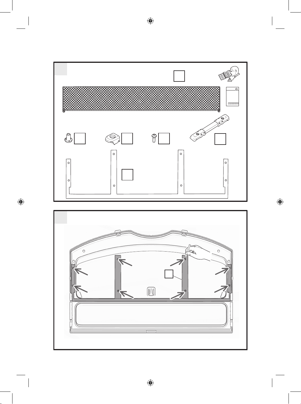
10
Fig. 7
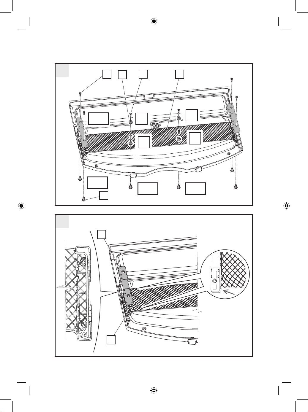
› From the top side of the parcel shelf, push the cap (C) into the hole you have drilled. Position
the cap such that its triangular shape ts exactly into the hole in the hook (D).
› Position the hook on the cap and screw it gently to the parcel shelf using the screw (E).
› The procedure for tting the other hook is exactly the same.
Please note: Ensure that the hook is positioned as shown in the
gure and that the stiffening rod running around the outside edge of
the net pocket is in the groove in the hook (see arrow).
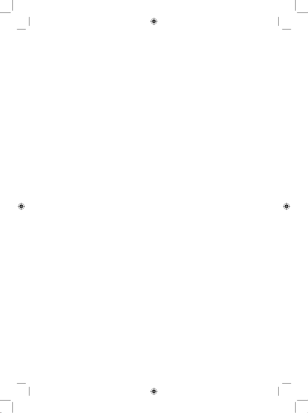
Fig. 8
› From the top side of the parcel shelf, push the cap (C) into the hole you have drilled. Position
the cap such that its triangular shape ts exactly into the hole in the hook (D).
› Position the hook on the cap and screw it gently to the parcel shelf using the screw (E).
› The procedure for tting the second hook is exactly the same.
Please note: Ensure that the hooks are positioned as shown in the
gure.
Fig. 9
› Hook the rubber edging of the net pocket into the hooks.
Check that all the screws have been tightened (gently) and place the parcel shelf with the
net pocket back in the luggage compartment.
Information on using and maintaining the net pocket/information
for the customer
›Do not overload the net pocket or place any objects with sharp edges in the net pocket.
› The load capacity of the net pocket is 1.5 kg. To avoid damaging the net pocket, do not
exceed its maximum load capacity. Over time, the net pocket may sag as a result of
long-term use or being overloaded. This constitutes natural wear and tear and does not
constitute grounds for a complaint.
›Only store lightweight items (such as clothing) in the net pocket.
›To avoid damaging the net pocket, do not place any objects that have hook-and-loop
fasteners in it.
›Do not continue using the net pocket if it becomes excessively worn or damaged.
Due to the nature of the net pocket with component number 5E5 065 110, the component
number is not marked on this component. Please retain these instructions for the entire
service life of this product.