T3 Innovation Coax Clarifier TCC200 User manual

User Manual
Coax Clarifier
TM
Test. Identify. Qualify.
Coax Run Mapping
Maps runs through splitters to show an
accurate picture of the coax system layout
using up to 4 Coax RF Remotes. Up to 12
ID Only Coax Remotes also available for
wiremapping on home runs.
Cable Length
Determines cable run length and reports
the location of an open or unterminated
cable.
Quality of Network
Measures overall network quality and
clearly depicts network reading as both a
bar graph and a digital return loss number,
measured in dB.
Tone Tracing
Traces coax runs with four unique tones
to quickly distinguish between respective
outlets.
99 Washington Street
Melrose, MA 02176
Phone 781-665-1400
Toll Free 1-800-517-8431
Visit us at www.TestEquipmentDepot.com

User Manual
TABLE OF CONTENTS
About this Manual...................................................................1
Symbols and Icons..............................................................2
Terms and Descriptions......................................................3
Safety Information..............................................................4
Accessories.....................................................................4
Design Features.......................................................................6
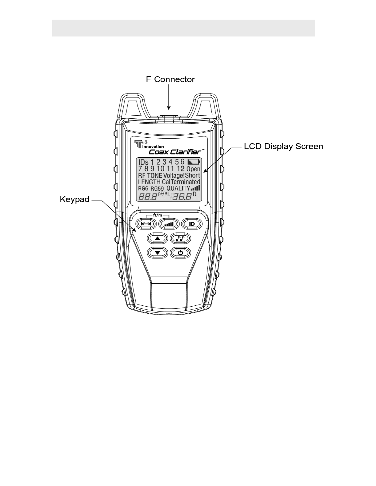
Coax Clarier™ Description.....................................................7
F-Connector................................................................7
LCD Display Screen............................................................8
Keypad.................................................................14
Operations.....................................................................16
Turning the Unit On/Off...................................................16
Automatic Power Down...................................................16
Cable Testing General Guidelines....................................17
Using Tone Mode.............................................................18
Trace Cable Runs..............................................................18
Measure Network Insertion Loss.....................................19
Prepare Test Unit........................................................19
Calibrate dB Loss Meter.............................................20
Measure Network Insertion Loss................................21
Test Splitters...............................................................21
Using Length Mode..........................................................22
Measure Cable Length...............................................22
Adjust Length Constant Value...................................24
Length Constant Accuracy..........................................26
Using ID Mode...................................................................27
RF Remote Battery Life...............................................29
Using Quality Mode..........................................................29
RF Remotes and Network Quality..............................30
Measure Network Quality..........................................30
Maintenance...............................................................32
Coax Clarier™ Battery Replacement.............................32
RF Remote Battery Replacement....................................32
Cleaning.......................................................................33
Storage....................................................................33
Customer Service...................................................................34
ContactingPlatinumTools..................................................34
Additional Accessories and Kits......................................34
Warranty Information.......................................................37
Product Registration..........................................................37
Disposal......................................................................37
Returns........................................................................37
Specications....................................................................38
Coax Clarifier
TM
Test. Identify. Qualify.

1
ABOUT THIS MANUAL
The Coax Clarier™ is a self contained, hand-held, battery powered
analyzer used by contractors, repair technicians, and other authorized
users. This device is used to quickly map coax cable runs, measure
network performance, determine cable length, and locate faults in “Dark”
(unpowered) residential and business cable networks. The test unit offers
the following features:
Feature Function
Length Testing Determines cable length and reports distance to an
open (unterminated) cable.
Coax Run Mapping Identies cables and determines their location by
mapping up to 4 runs through a splitter using Coax
RF remotes and up to 12 cables using ID Only Coax
remotes.
Quality Testing Measures overall network quality and clearly depicts
network reading as both a bar graph and a digital
return loss number, measured in decibels (dB).
Tone Tracing Traces coax runs, with the use of a tone probe, using
four tones to easily distinguish between cable outlets
and quickly map the network layout.
Insertion Loss Measures the insertion loss of a single coax run.
Fault Detection Identies Open and Short cable faults.

2
Symbol Denition
Warning: Potential for personal injury
Caution: Potential for damage or destruction to equipment.
Voltage! Voltage detection symbol. Immediately disconnect test unit
from source of voltage.
Act Sig
If an active signal is detected, immediately disconnect test unit
from active signal source. If the unit is not disconnected from
the source, the Coax Clarier™ will turn off after 90 seconds.
Conformité Européenne. Conforms with European Economic
Area directives.
Disposal information.
Symbols & Icons
The following symbols are used throughout the manual or in the display
screen of the Coax Clarier™ to help you avoid personal injury and
potential damage to the test equipment (see Table 1).
!
Table 1. Symbols and Icons

3
Terms Description and Uses
Coax Cable Video cable with a single pair (2 pin) wiring system.
▪Common coax cable types are RG6 and RG59.
Run An end-to-end cable connection. Run can refer to a
single cable or multiple cables connected together
with a splitter or barrel connector.
Coax Network Multiple coax cables connected by splitters or home
run congurations to concentration panels.
Length Constant
Value The amount of capacitance in picofarads (pF) per
unit distance.
Insertion Loss A measurement of the network’s ability to carry
a signal from a power source to a receiver at the
opposing end of a run. Network insertion loss is
measured in dB and represents the percentage of
signal that is successfully transmitted through a run.
Return Loss A common measurement of coax networks, return
loss is a measure of Voltage Standing Wave Ratio
(VSWR), expressed in dB. It ranges from 0.0 dB for a
cable with a dead short to innity for a perfect cable
with absolutely no signal loss.
▪The Coax Clarier™ reports the return loss value
from 0.0 dB to 40.0 dB, with 40.0 being the best
possible network quality.
Splitter A device used to route a single signal source to two
or more devices.
F-Connector Connector for a coax cable.
Terms and Descriptions
Table 2 denes the terms used throughout the manual and provides
information to assist you with proper operation and understanding of the
unit and its functions.
Table 2. Terms and Descriptions

4
Safety Information
To ensure safe operation of the Coax Clarier™, follow the instructions
carefully and observe the warning and caution messages listed in Table
3. Failure to observe warnings can result in severe injury or death and can
damage the unit.
Table 3. Safety Information
Notication Denition
The Coax Clarier™ is designed for use on unenergized
cabling systems. Connecting the Coax Clarier™ to live AC
power may damage the unit and pose a safety hazard for
the user.
Do not place equipment or its accessories in the trash.
Items must be properly disposed in accordance with local
regulations.
The accessories listed in Table 4 are used with the Coax Clarier™
to identify runs and test coax networks. The provided accessories are
dependent on the kit you purchased. The Additional Accessories and
Kits section contains a detailed list of each kit as well as additional
products that can help make testing easier.
ACCESSORIES

5
Table 4. Coax Clarier™ Accessories
Accessory Product
Number Description
18303 Adapter, F-Jack to BNC Jack
18304 Adapter, F–Jack to Push-On Plug
18301 F-Connector Coupler, F81
18306 F-Terminator Plug
TCA004 Cable Assembly, Screw-On F-Jack to
Push-On F-Plug Cable – 12”
TCR001
TCR002
TCR003
TCR004
Coax RF Remotes
▪No. 1 Coax RF Remote
▪No. 2 Coax RF Remote
▪No. 3 Coax RF Remote
▪No. 4 Coax RF Remote
TRK104
TRK112
ID Only Coax Remotes
▪Nos. 1 – 4 ID Only Coax Remote Set in
Foam Holder
▪Nos. 1-12 ID Only Coax Remote Set in
Foam Holder (Illustrated)
1 2 3 4
5 6 7 8
9 10 11 12
Remote
3
Remote
4
Remote
2
Remote
1
Note: All accessories listed in Table 4 are available for purchase
through Platinum Tools. Refer to the Customer Service
section for contact information.

6
DESIGN FEATURES
▪Easy to operate
▪One pass coax cable run mapping
▪Tests through splitters
▪Identies open (unterminated) cables
▪Extra large seven-segment, backlight LCD screen with icons that
clearly display test results
▪Displays coax cable run quality
▪Tests and grades splitter performance
▪Measures length of coax cable in feet or meters
▪Identies up to 4 RF remotes and 12 ID Only Coax remotes
▪Automatic pre-test voltage checks
▪Measures single cable length up to 1,500 ft
▪Tone generator with selectable tone cadence to easily trace cable runs
▪Conserves power and supports long battery life with Auto-off feature
and battery low icon
▪Four AA alkaline batteries provided with your purchase

7
COAX CLARIFIER™ DESCRIPTION
Figure 1. Coax Clarier™
F-Connector
One F-Connector is located at the top of the Coax Clarier™. The
connector enables you to test and measure single cables and coax
networks.
Note: An F-Connector coupler is provided with your purchase of the
Coax Clarier™.
The Coax Clarier™, illustrated in Figure 1, has three main parts: the
F-Connector, the LCD display screen, and the keypad.

8
Battery Low Icon
Detected Remotes
Tone Mode
Length Mode
Length Constant Value
Cable Types
Measured Length
Quality Mode and
Bar Graph
}
Cable Conditions
Voltage Detected Warning
Calibration Icon
Return Loss Icon
LCD Display Screen
The Coax Clarier™ has a high contrast, backlight LCD display screen,
shown in Figure 2 below. The LCD display screen shows the following:
cable conditions, test modes and related icons, calibration icon, voltage
detected warning, active signal warning, and battery capacity.
Cable Conditions
The device checks for three cable conditions during testing: Open, Short,
and Terminated. The cable conditions, explained in Table 5, appear in a
column below the battery low icon in the LCD display screen.
Table 5. Cable Conditions
Cable Conditions Description
Open An “Open” error indicates a wire connection within
the cable is not continuous throughout the length
of the cable.
Short The “Short” icon appears when the two wires
within a cable are electrically connected. This is
also known as a short circuit.
Terminated The “Terminated” icon will appear when the far end
of the run has an F-Terminator Plug in place or is
wired to a device.
Figure 2. LCD Display Screen

9
ID Mode
When the Coax Clarier™ is set to ID Mode, the “ID” and “RF” icons
appear in the top left corner of the LCD display screen. Table 6 describes
the numbers and icons that appear in the display screen according to three
testing scenarios.
Table 6. ID Mode Numbers and Icons
Test Scenario Displayed Numbers and Icons
Detected Remotes Indentied remotes 1-12 display in the top two rows
of the LCD display screen.
▪When an ID Only Coax remote is detected, the
“RF” icon disappears from view.
▪The “IdLE” icon appears in the lower right
corner of the display screen when mapping is
complete and all remotes are detected.
Unterminated Runs RF and ID Only Coax remotes are not identied on
unterminated runs.
▪The “Open” icon appears in the right side of
the display screen to indicate the network is
unterminated.
▪The halt icon, “HLt”, displays in the right side of
the screen demonstrating the unit is idle and the
test was incomplete (see Figure 3).
Poor Network Quality ID mode does not function on a coax network with a
poor quality reading (< 17 dB).
▪When the network quality is low, mapping stops,
the “QUALITY” icon ashes, and the “HLt” icon
appears in the lower right corner of the display
screen (see Figure 4).
Figure 3. ID Mode with Unterminated Run Figure 4. ID Mode with Poor Network Quality

10
Length Mode
The “Length” icon appears in the left side of the LCD display screen when
the LENGTH button is pressed. When the unit is set to measure cable
length, the length reading and measurement specications described in
Table 7 appear in the LCD display screen (see Figure 5).
Table 7. Length Mode Measurement Specications
Length Specications Description
Cable Types The cable types (RG6, RG59, or no specied
type) appear in the lower left of the LCD display
screen.
▪Each type of cable has its own length constant
value, which is used to properly measure cable
length.
Length Constant Value A value measured in picofarads (pF) per foot or
meter appears in the lower left corner of the
LCD display screen. This value corresponds to
the selected cable type and can be adjusted at
any time.
Measured Length The length of the measured cable displays in
units of feet or meters in the lower right corner
of the screen.
Figure 5. Length Measurement for Unspecied Cable
Note: When the network quality is low, be sure that all cable ends
are terminated. Unterminated cables result in signal loss. Use
F-Terminator Plugs as needed to improve network quality.

11
Note: Refer to the Using Length Mode section to learn how to
change the unit of measurement, adjust the length constant
value for each cable type, and measure cable length.
Note: Using F-Terminator Plugs on unterminated cable ends will
improve network quality and lower return loss.
Quality Mode
When the QUALITY button is pressed the “Quality” icon displays in the
lower right corner of the LCD display screen and a bouncing ball activity
indicator is shown in the lower left corner of the screen. When testing
network quality, the following icons and values appear in the screen (see
Figure 6):
▪Bar Graph – The bar graph depicts the overall quality of the network
being tested. The bar graph, appearing in the lower right of the screen,
corresponds to the measured return loss and will adjust (increasing or
decreasing in the visual bars shown) as the return loss value uctuates.
Refer to the Using Quality Mode section for a description of what each
bar represents in terms of network quality.
▪Return Loss (RL) – When the unit produces a return loss value for the
network quality, the “RL” icon appears to the left of the measured return
loss value. Return loss is measured in dB and displays in the lower right
corner of the screen.
Figure 6. Return Loss Measurement in Quality Mode

12
Tone Mode
When the TONE button is pressed, the “Tone” icon appears in the middle
of the LCD display screen and a bouncing ball activity indicator is shown
in the lower left corner of the screen. The “RF” symbol will display to the
left of the “Tone” icon when you set Tone Mode to measure the network’s
insertion loss. When using Tone Mode, the icons and values described in
Table 8 appear in the LCD display screen.
Table 8. Tone Mode Icons and Values
Icons and Values Description
Tone Path Selection The selected cadence is transmitted on the coax
pin (“P”), the coax shield (“S”), or both the pin and
shield (“PS”).
▪The icons related to the current tone path selection
appear in the lower left corner of LCD display
screen.
Frequency If the unit is set to measure network insertion
loss, one of the following frequencies (measured
in MHz) displays in the lower right corner of the
screen: 10.0, 20.0, 30.0, or 40.0 (see Figure 7).
Cadence If the unit is set to identify cable runs, one of the
following tone options appears in the lower right
corner of the display screen: HL1, HL2, Hi, and Lo
(see Figure 8).
Note: Refer to the Using Tone Mode section to learn how to run
the two tone tests.
Figure 7. RF Tone with 10.0 MHz Frequency Figure 8. Tone Mode with Lo Cadence

13
Cal
The “Cal” icon ashes in the middle of the LCD display screen when
editing the length constant value in Length Mode and during calibration
testing. The Coax Clarier™ performs a calibration and self-test pass
before starting Quality or ID testing.
If calibration fails, the “Cal” icon ashes to indicate that the unit failed
to initialize properly. Hold down the POWER button to turn the unit off or
press the test mode button again (QUALITY or ID) to proceed with testing.
Battery Low
The battery low icon appears when the battery is nearing depletion.
The symbol ashes when there is 30 minutes of remaining battery life
indicating the battery needs to be replaced. Results may be unreliable at
this point.
Voltage Detected Warning (Voltage!)
If voltage is detected on the cable the “Voltage!” icon ashes. A check for
voltage is performed before each test and during most tests when looping
or changing test parameters. If voltage is detected, testing stops. If the
icon appears, the Coax Clarier™ should be immediately disconnected
from the source of the voltage.
Active Signal Warning (Act Sig)
When an active signal is detected, the “Act Sig” message ashes at the
bottom of the display screen. If an active signal is found, the unit should
be immediately disconnected from the signal source. The Coax Clarier™
will automatically turn off after 90 seconds if the unit is not disconnected
from the active signal.

14
Keypad
The Coax Clarier™ is equipped with seven buttons, illustrated in Figure 9.
Four buttons, appearing in the top two rows of the keypad, are used to operate
test modes (ID, Length, Quality, and Tone). Two Up/Down buttons are used to
edit. One button is used to power the unit On/Off and toggle the backlight On/
Off. The button functions are explained in Table 9.
Table 9. Keypad
Button Function
Length The Length Mode button is used to measure the length of a
single, unterminated cable in feet or meters.
▪A short press of the Length and Quality buttons simultaneously
toggles between length measurement units of feet and meters.
▪A long press (two seconds) of the Length button allows you to
edit the length constant.
Quality The Quality Mode button measures the overall quality of a coax
network by measuring the network’s return loss (calibrated in dB).
▪A short press of the button runs a loop test on the network every
30 seconds.
ID The ID Mode button is used with ID Only Coax remotes and RF
remotes to identify cable runs.
▪A short press of the ID button runs a single scan of the network.
▪ID Mode scans and identies up to 4 RF remotes or 1-12
possible ID Only Coax remotes in the network.
Quality
ID
Tone
Power/Backlight
Up/Down
Length
Toggle Units
Figure 9. Keypad

15
Button Function
Tone The Tone Mode button offers two types of testing: tone tracing
(TONE) and measuring network insertion loss (RF TONE).
TONE
▪A short press of the button transmits a 0 – 1 kHz cadence from
the unit through the connected cable.
▪Subsequent presses of the Tone button steps through the three
tone path options (coax pin, coax shield, or coax pin and shield).
RF TONE
Used to determine the network insertion loss (measured in dB)
with the use of a compatible dB Loss meter.
▪A short press of the Tone button transmits a frequency from the
unit through the connected cable.
Up/Down ▪In Tone Mode, the Up and Down buttons allow you to select a
tone test (TONE or RF TONE) and their respective cadence or
frequency.
▪In Length mode, the Up and Down buttons are used to select
cable types and adjust (increment/decrement) length constant
values.
Power ▪A short press of the Power button enters Quality Mode.
▪Short presses of any test mode button turns the unit On.
▪Subsequent presses of the Power button toggle the backlight
On and Off.
▪A long press (two seconds) of the Power button turns the
unit off.
Table 9. Keypad (Continued)

16
Turning the Unit On/Off
Turn Unit On
▪Press any test mode button to turn the unit ON. The LCD display
screen updates according to the test mode selected.
Turn Unit Off
▪Press and hold down the POWER button for two seconds to turn the
unit OFF. The display screen will go blank.
Automatic Power Down
The Coax Clarier™ automatically turns off after a period of inactivity to
conserve battery power. The automatic power down feature is dependent
on which test modes are in use and if voltage is detected in the network
(see Table 10).
Table 10. Automatic Power Down.
OPERATIONS
To ensure safe operation of the Coax Clarier™, follow the instructions
carefully and pay attention to warning and caution symbols. Failure to
observe warnings can result in severe injury or death and can damage the
unit.
Test Mode Time
Tone 60 minutes
Length 5 minutes
Quality 5 minutes
ID 5 minutes
Voltage Detected 90 seconds

17
Cable Testing General Guidelines
The Coax Clarier™ tests several coax cable network parameters by
measuring the overall network quality, determining the network’s insertion
loss, identifying cable runs by sound, locating remotes, and calibrating
cable length.
Important Points to Note
▪The unit should be OFF when you connect a cable.
▪The F-Connector coupler must be afxed to the F-Connector on the top
of the unit in order to properly connect cables.
Important Safety Points
The Coax Clarier™ is designed for use on unenergized cabling
systems. Connecting the Coax Clarier™ to live AC power may
damage the unit and pose a safety hazard for the user.
If the Voltage! icon appears, the Coax Clarier™ should be
disconnected immediately from the source of the voltage.
If an active signal is detected, the bottom of the LCD display
screen ashes “Act Sig”. Immediately disconnect the
Coax Clarier™ from the signal source. The unit turns OFF
automatically after 90 seconds if it’s not disconnected.
!
!
!

18
Using Tone Mode
Tone Mode offers two types of testing: tone tracing (TONE) and measur-
ing network insertion loss (RF TONE). Setting the unit to TONE emits a
cadence from the test unit through the connected cable. With the use of
a tone probe, you can easily locate the cable carrying sound. Selecting RF
TONE sends a frequency from the main test unit through the connected
cable. The frequency is detected by a dB Loss meter, which calculates the
network insertion loss.
Note: For the rst use of Tone Mode, the unit is set to TONE for tone
tracing. The tone path defaults to Pin (P) with frequency HL1.
For subsequent uses of Tone Mode, the tone path and test last
selected will be restored in the unit’s memory.
Trace Cable Runs
In order to identify cables with the use of a tone probe, the Coax
Clarier™ must be set to TONE.
1. Connect one end of the coax cable to the F-Connector coupler on
the unit.
2. Press the TONE button. The LCD display screen shows the following
icons upon entering Tone Mode (see Figure 10):
▪The test last used (TONE or RF TONE).
▪A bouncing ball activity indicator in the lower left corner.
▪The tone path last selected: coax pin (P), coax shield (S), or both
coax pin and shield (PS).
▪Cadence or frequency last selected.
Figure 10. Tone Test with Lo Cadence and Coax Pin Slected
Table of contents
Other T3 Innovation Test Equipment manuals