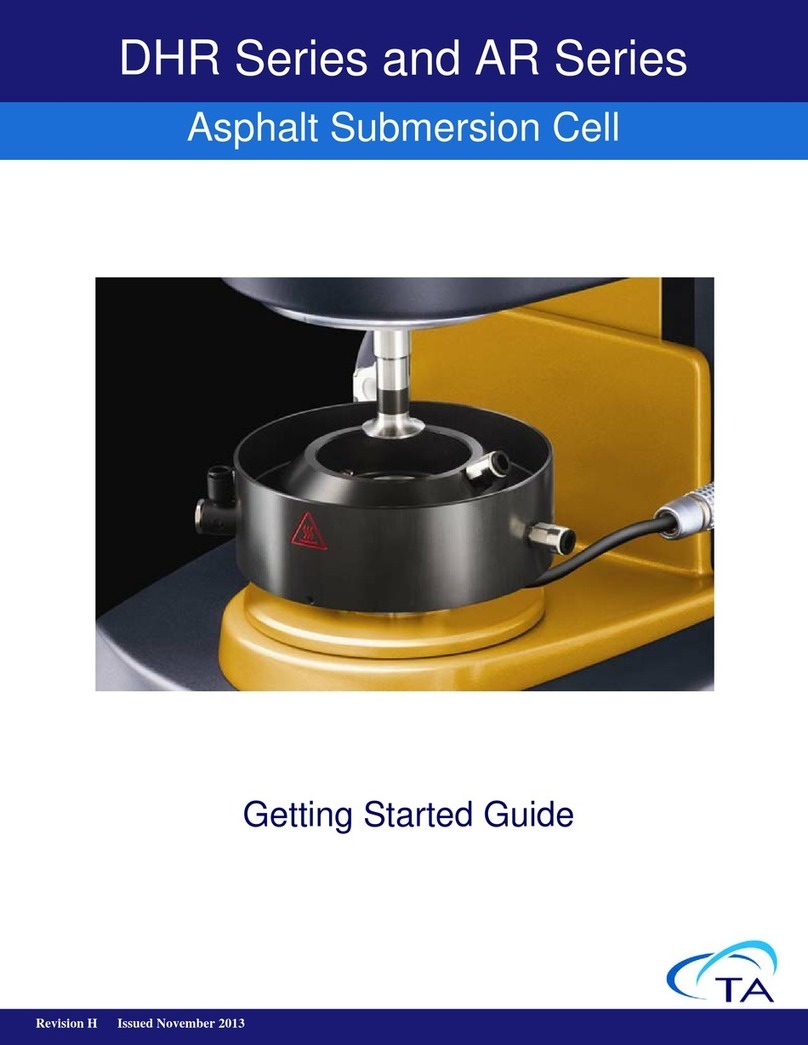
TA Instruments DHR Series User manual

Revision H Issued August 2014
Getting Started Guide
DHR Series and AR Series
Peltier Plate

Page 2 DHR/AR Series Peltier Plate Getting Started Guide
Notice
The material contained in this manual, and in the online help for the software used to support this instru-
ment, is believed adequate for the intended use of the instrument. If the instrument or procedures are used
for purposes other than those specified herein, confirmation of their suitability must be obtained from TA
Instruments. Otherwise, TA Instruments does not guarantee any results and assumes no obligation or liabil-
ity. TA Instruments also reserves the right to revise this document and to make changes without notice.
TA Instruments may have patents, patent applications, trademarks, copyrights, or other intellectual prop-
erty covering subject matter in this document. Except as expressly provided in written license agreement
from TA Instruments, the furnishing of this document does not give you any license to these patents, trade-
marks, copyrights, or other intellectual property.
TA Instruments Operating Software, as well as Module, Data Analysis, and Utility Software and their asso-
ciated manuals and online help, are proprietary and copyrighted by TA Instruments. Purchasers are granted
a license to use these software programs on the module and controller with which they were purchased.
These programs may not be duplicated by the purchaser without the prior written consent of TA Instru-
ments. Each licensed program shall remain the exclusive property of TA Instruments, and no rights or
licenses are granted to the purchaser other than as specified above.
©2013 by
TA Instruments — Waters LLC
159 Lukens Drive
New Castle, DE 19720

DHR/AR Series Peltier Plate Getting Started Guide Page 3
Introduction
Important: TA Instruments Manual Supplement
Please click the TA Manual Supplement link to access the following important information
supplemental to this Getting Started Guide:
• TA Instruments Trademarks
• TA Instruments Patents
• Other Trademarks
• TA Instruments End-User License Agreement
• TA Instruments Offices

Page 4 DHR/AR Series Peltier Plate Getting Started Guide
Notes, Cautions, and Warnings
This manual uses NOTES, CAUTIONS, and WARNINGS to emphasize important and critical
instructions. In the body of the manual these may be found in the shaded box on the outside of the page.
NOTE: A NOTE highlights important information about equipment or procedures.
CAUTION: A CAUTION emphasizes a procedure that may damage equipment or cause loss of data
if not followed correctly.
MISE EN GARDE: UNE MISE EN GARDE met l'accent sur une procédure susceptible d'endom-
mager l'équipement ou de causer la perte des données si elle n'est pas correctement suivie.
Regulatory Compliance
Safety Standards
For Canada
CAN/CSA-C22.2 No. 61010-1 Safety requirements for electrical equipment for measurement, control, and
laboratory use, Part 1: General Requirements.
CAN/CSA-C22.2 No. 61010-2-010 Particular requirements for laboratory equipment for the heating of
materials.
For European Economic Area
(In accordance with Council Directive 2006/95/EC of 12 December 2006 on the harmonization of the laws
of Member States relating to electrical equipment designed for use within certain voltage limits.)
EN 61010-1:2001 Safety requirements for electrical equipment for measurement, control, and laboratory
use, Part 1: General Requirements + Amendments.
EN 61010-2-010:2003 Particular requirements for laboratory equipment for the heating of materials +
Amendments.
For United States
UL61010-1:2004 Electrical Equipment for Laboratory Use; Part 1: General Requirements.
UL61010A-2-010:2002 Particular requirements for laboratory equipment for the heating of materials +
Amendments.
A WARNING indicates a procedure that may be hazardous to the operator or
to the environment if not followed correctly.
Un AVERTISSEMENT indique une procédure qui peut être dangereuse pour
l'opérateur ou l'environnement si elle n'est pas correctement suivie.

DHR/AR Series Peltier Plate Getting Started Guide Page 5
Electromagnetic Compatibility Standards
For Australia and New Zealand
AS/NZS CISPR11:2004 Limits and methods of measurement of electronic disturbance characteristics of
industrial, scientific and medical (ISM) radio frequency equipment.
For Canada
ICES-001 Issue 4 June 2006 Interference-Causing Equipment Standard: Industrial, Scientific, and Medical
Radio Frequency Generators.
For the European Economic Area
(In accordance with Council Directive 2004/108/EC of 15 December 2004 on the approximation of the
laws of the Member States relating to electromagnetic compatibility.)
EN61326-1:2006 Electrical equipment for measurement, control, and laboratory use-EMC requirements-
Part 1: General Requirements. Emissions: Meets Class A requirements per CISPR 11. Immunity: Per
Table 1 - Basic immunity test requirements.
For the United States
CFR Title 47 Telecommunication Chapter I Federal Communications Commission, Part 15 Radio
frequency devices (FCC regulation pertaining to radio frequency emissions).

DHR/AR Series Peltier Plate Getting Started Guide Page 6
Safety
Do not attempt to service this instrument, as it contains no user-serviceable components.
Required Equipment
While operating this instrument, you must wear eye protection that either meets or exceeds ANSI Z87.1
standards. Additionally, wear protective clothing that has been approved for protection against the
materials under test and the test temperatures.
Instrument Symbols
The following label is displayed on the instrument for your protection:
Please heed the warning labels and take the necessary precautions when dealing with these areas. This
Getting Started Guide contains cautions and warnings that must be followed for your own safety.
Cautions and Warnings
Symbol Explanation
This symbol indicates that a hot surface may be present. Take care not to touch
this area or allow any material that may melt or burn come in contact with this
hot surface.
Ce symbole indique la présence possible d'une surface chaude. Prenez soin de
ne pas toucher cette zone ou de laisser un matériau susceptible de fondre ou de
brûler entrer en contact avec cette surface chaude.
WARNING: The material used on the top surface of the Peltier Plate is hard,
chrome-plated copper. The material used for the 'skirt' of the standard Peltier is
stainless steel, and Nylon for the Dual Stage Peltier. Therefore, use an appropri-
ate cleaning material when cleaning the Peltier Plate.
AVERTISSEMENT: Le matériau utilisé à la surface supérieure de la plaque Peltier
est du cuivre chromé rigide. Le matériau utilisé pour la 'jupe' de la plaque Peltier
standard est l'acier inoxydable et celui utilisé pour la double platine Peltier est le
Nylon. Par conséquent, utilisez l'équipement approprié pour le nettoyage de la
plaque Peltier.
WARNING: Take adequate precautions prior to heating of materials if it can lead
to explosion, implosion or the release of toxic or flammable gases.
AVERTISSEMENT: Prenez des mesures de précaution adéquates avant de
chauffer des matériaux, si cela peut entraîner l'explosion, l'implosion ou le
dégagement de gaz toxiques ou inflammables.

DHR/AR Series Peltier Plate Getting Started Guide Page 7
CAUTION: The Peltier Plate may be damaged by operating the instrument without a flow of water
through the Peltier Plate. There is a Peltier overheat protection device that will activate if the device
becomes too hot.
MISE EN GARDE: La plaque Peltier peut être endommagée si l'instrument est utilisé sans écoule-
ment d'eau dans la plaque Peltier. Il existe un dispositif de protection contre la surchauffe qui
s'active si le dispositif devient trop chaud.

DHR/AR Series Peltier Plate Getting Started Guide Page 8
Table of Contents
Introduction ......................................................................................................................................... 3
Important: TA Instruments Manual Supplement . . . . . . . . . . . . . . . . . . . . . . . . . . . . . . . . . . .3
Notes, Cautions, and Warnings . . . . . . . . . . . . . . . . . . . . . . . . . . . . . . . . . . . . . . . . . . . . . . . . .4
Regulatory Compliance . . . . . . . . . . . . . . . . . . . . . . . . . . . . . . . . . . . . . . . . . . . . . . . . . . . . . . .4
Safety Standards . . . . . . . . . . . . . . . . . . . . . . . . . . . . . . . . . . . . . . . . . . . . . . . . . . . . . . . . .4
Electromagnetic Compatibility Standards . . . . . . . . . . . . . . . . . . . . . . . . . . . . . . . . . . . . . . . . .5
Safety . . . . . . . . . . . . . . . . . . . . . . . . . . . . . . . . . . . . . . . . . . . . . . . . . . . . . . . . . . . . . . . . . . . . .6
Required Equipment . . . . . . . . . . . . . . . . . . . . . . . . . . . . . . . . . . . . . . . . . . . . . . . . . . . . . .6
Instrument Symbols . . . . . . . . . . . . . . . . . . . . . . . . . . . . . . . . . . . . . . . . . . . . . . . . . . . . . .6
Cautions and Warnings . . . . . . . . . . . . . . . . . . . . . . . . . . . . . . . . . . . . . . . . . . . . . . . . . . . .6
Chapter 1:
Introducing the Peltier Plate .......................................................................................... 9
Overview . . . . . . . . . . . . . . . . . . . . . . . . . . . . . . . . . . . . . . . . . . . . . . . . . . . . . . . . . . . . . . . . . . . . .9
Accessories for the Standard Peltier Plate . . . . . . . . . . . . . . . . . . . . . . . . . . . . . . . . . . . . . . . . . . .11
Solvent Trap . . . . . . . . . . . . . . . . . . . . . . . . . . . . . . . . . . . . . . . . . . . . . . . . . . . . . . . . . . . . . .11
Purge Gas Cover . . . . . . . . . . . . . . . . . . . . . . . . . . . . . . . . . . . . . . . . . . . . . . . . . . . . . . . . . . .11
Insulating Thermal Cover . . . . . . . . . . . . . . . . . . . . . . . . . . . . . . . . . . . . . . . . . . . . . . . . . . . .11
Peltier Immersion Ring . . . . . . . . . . . . . . . . . . . . . . . . . . . . . . . . . . . . . . . . . . . . . . . . . . . . . .11
Peltier Plate Covers . . . . . . . . . . . . . . . . . . . . . . . . . . . . . . . . . . . . . . . . . . . . . . . . . . . . . . . . .11
Peltier Plate Camera Viewer . . . . . . . . . . . . . . . . . . . . . . . . . . . . . . . . . . . . . . . . . . . . . . . . . .11
Variants of Standard Peltier Plate . . . . . . . . . . . . . . . . . . . . . . . . . . . . . . . . . . . . . . . . . . . . . . . . .12
Stepped Peltier Plate . . . . . . . . . . . . . . . . . . . . . . . . . . . . . . . . . . . . . . . . . . . . . . . . . . . . . . . .12
Stepped Disposable Plate . . . . . . . . . . . . . . . . . . . . . . . . . . . . . . . . . . . . . . . . . . . . . . . . . . . .12
Advanced Peltier Plate . . . . . . . . . . . . . . . . . . . . . . . . . . . . . . . . . . . . . . . . . . . . . . . . . . . . . .13
Installing a Quick Change Plate . . . . . . . . . . . . . . . . . . . . . . . . . . . . . . . . . . . . . . . . . . . .13
Un-installing a Quick-Change Plate . . . . . . . . . . . . . . . . . . . . . . . . . . . . . . . . . . . . . . . . .14
Dual Stage Peltier Plate (DSPP) . . . . . . . . . . . . . . . . . . . . . . . . . . . . . . . . . . . . . . . . . . . . . . . . . .15
System Specifications . . . . . . . . . . . . . . . . . . . . . . . . . . . . . . . . . . . . . . . . . . . . . . . . . . . . . . . . . .16
Ramp Rate . . . . . . . . . . . . . . . . . . . . . . . . . . . . . . . . . . . . . . . . . . . . . . . . . . . . . . . . . . . . . . . .16
Chapter 2:
Installing the Peltier Plate ............................................................................................ 18
Using the Smart Swap™ . . . . . . . . . . . . . . . . . . . . . . . . . . . . . . . . . . . . . . . . . . . . . . . . . . . . . . . .18
Installing the Lower Stage . . . . . . . . . . . . . . . . . . . . . . . . . . . . . . . . . . . . . . . . . . . . . . . . . . .18
Removing the Lower Stage . . . . . . . . . . . . . . . . . . . . . . . . . . . . . . . . . . . . . . . . . . . . . . . . . . .20
Index ................................................................................................................................................... 21
DHR/AR Series Peltier Plate Getting Started Guide Page 9
Chapter 1:
Introducing the Peltier Plate
Overview
The standard Peltier Plate (schematic shown in the figure below) is the most widely used temperature con-
trol system for the rheometers. It uses the Peltier thermoelectric effect to control the temperature accu-
rately, with rapid heating and cooling. The plate consists of a copper disc, with hard chrome plating on the
upper surface. A Pt100 temperature probe is embedded in the disc, in thermal contact with it and close to
the surface. Copper is used as the disc material for its very high thermal conductivity, ensuring negligible
temperature gradients across the surface of the plate. The hard chrome plating prevents mechanical or
chemical damage to the plate.
The basis of the Peltier effect is this: When an electric current passes across the junction between two dis-
similar metals or semiconductors, a temperature gradient across the junction results—the temperature will
rise on one side and fall on the other. The direction of the current determines on which side the temperature
rises.
On the DHR rheometer plates, a set of Peltier elements is placed below and in thermal contact with the
copper disc. The desired level of active heating or cooling can be achieved by controlling the direction and
magnitude of the current supplied to these elements.
Figure 1 Peltier Plate schematic diagram.
Since a temperature gradient can only be maintained by the input of energy, the Peltier plate requires a heat
sink to remove any waste heat. This is provided by a coolant fluid, normally water, passing through a fluid
jacket situated below the Peltier elements. If the fluid circulating through the fluid jacket is from a closed
reservoir, then its temperature will rise unless it is actively cooled, particularly when the Peltier plate is
operating at temperatures far from ambient.
80 mm diameter copper
with hardened chrome
surface
Peltier heating elements
Platinum Resistance
Thermometer (PRT)
Heat sink connections
Heat sink fluid jacket
Smart Swap™ base

DHR/AR Series Peltier Plate Getting Started Guide Page 10
Typical temperature ranges for different cooling fluid configurations are given in the “System
Specifications” section.
The flow rate of the fluid through the bath does not need to be high. A flow rate of at 0.5 liters per minute
is usually adequate, although this should be increased to 1 liter per minute when working at very low tem-
peratures. If this flow rate is not maintained, the Peltier will lose the ability to provide cooling.
Measuring systems available for use with the Peltier Plate are the cone and plate and parallel plate.

DHR/AR Series Peltier Plate Getting Started Guide Page 11
Accessories for the Standard Peltier Plate
Solvent Trap
Many samples are prone to drying due to solvent evaporation during testing. The Solvent Trap cover and
Solvent Trap geometry work in concert to create a thermally stable vapor barrier, virtually eliminating any
solvent loss during the experiment. The geometry includes a well that contains very low viscosity oil, or
even the volatile solvent present in the sample. The Solvent Trap cover includes a blade that is placed into
the solvent contained in the well without touching any other part of the upper geometry. The Solvent Trap
sits directly on top of the Peltier Plate surface and an insulating centering ring ensures perfect placement
for quick and easy sample loading.
Purge Gas Cover
The purge gas environmental cover is a hard-anodized aluminum two-piece split cover with 6-mm
diameter compression fittings. An insulating location ring ensures precise and easy location of the cover.
This cover is ideal for purging the sample area with nitrogen to prevent condensation during experiments
performed below room temperature or with a humidified purge to keep a sample from drying.
Insulating Thermal Cover
The thermal insulation cover is constructed of an anodized aluminum core surrounded by an insulating
cover. The aluminum core conducts heat to the upper geometry providing uniform temperature throughout
the sample. Recommended for use over a temperature range of -10°C to 90°C, with samples not suscepti-
ble to drying such as oils, caulk, epoxy, and asphalt binder. Heat break geometries are recommended for
use with the cover.
Peltier Immersion Ring
The Peltier Plate immersion ring allows samples to be measured while fully immersed in a fluid. The
immersion ring is compatible with all Peltier Plate models and is easily attached to the top of the Peltier
Plate. A rubber ring provides the fluid seal. This option is ideal for studying the properties of hydrogels.
Peltier Plate Covers
A variety of Peltier Plate covers are available for applications that can harm the chromium surface of the
plate or for samples that exhibit slip during testing. They are available in stainless steel, hard-anodized alu-
minum and titanium. Crosshatched and sandblasted Peltier covers are used to eliminate sample slippage
effects. Covers are compatible with solvent trap.
Peltier Plate Camera Viewer
The camera viewer is used in conjunction with streaming video and image capture software. Real time
images can be displayed in the software and an image can be stored with each data point for subsequent
viewing during data analysis. The camera viewer is perfect for long experiments with unattended operation
as visual inspections of data integrity.

DHR/AR Series Peltier Plate Getting Started Guide Page 12
Variants of Standard Peltier Plate
There are three variants of the standard Peltier Plate: Stepped, Stepped Disposable, and Advanced.
Stepped Peltier Plate
The Stepped Peltier Plate has a raised center section with a thread for attaching screw-in plates. This is
most commonly used with 25 and 8 mm screw-in plates and Upper Heated Plate (UHP) for asphalt binder
tests.
Figure 2 Stepped Peltier Plate.
Stepped Disposable Plate
The Stepped Disposable Plate has a raised center section with a clear hole and locking hex screws to
accommodate both disposable plates, and lower Tribo-rheology geometries.
Figure 3 Stepped Disposable Plate.
Stepped Peltier Plate
Stepped Disposable Plate
Hex screw

DHR/AR Series Peltier Plate Getting Started Guide Page 13
Advanced Peltier Plate
The Advanced Peltier Plate can be used as a standalone base plate for use with upper geometries up to 50
mm diameter, or it can be used with interchangeable quick-change plates via the use of the bayonet mount-
ing ring. A range of quick-change plates are available in different materials, with steps, different surface
finishes (cross-hatched, and sandblasted), or as disposable. These are also compatible with the ARES-G2
APS.
Installing a Quick Change Plate
1Toinstalla quick-changeplate,simply positioniton the top raisedsection of theAdvanced Peltier Plate,
andlockinplacewiththebayonetmountingringensuringthatthequickchangeplateiscorrectlycentered.
Figure 4 Quick-change plate.
Figure 5 Bayonet mounting ring.
Quick-change plate
Advanced Peltier Plate
Bayonet mounting ring

DHR/AR Series Peltier Plate Getting Started Guide Page 14
2Use needle-nose pliers to lock the mounting ring into place. Refer to the image below.
Figure 6 Install the quick change plate.
Un-installing a Quick-Change Plate
To remove a quick-change plate use the needle-nose pliers to unlock the mounting ring. Refer to the image
below:
Figure 7 Un-install the quick change plate.

DHR/AR Series Peltier Plate Getting Started Guide Page 15
Dual Stage Peltier Plate (DSPP)
The Dual Stage Peltier Plate (DSPP) is a system optimized for low temperature measurements using the
standard four element array as a heat sink for a single Peltier element and top plate. This still has the same
maximum temperature as the standard plate, but because the lower Peltier elements are the heat sink for the
top element rather than a circulating fluid, low temperatures can be reached quickly, and without the use of
expensive refrigerated fluid circulators.
Figure 8 The Dual Stage Peltier Plate.
For optimum performance at low temperatures, use heat break geometries. The gas purge cover
(P/N 529612.901) can also be used to reduce frosting.

DHR/AR Series Peltier Plate Getting Started Guide Page 16
System Specifications
The table found below contains the technical specifications for the Peltier Plate.
CAUTION: The Peltier Plate may be damaged by operating the instrument without a flow of water
through the Peltier Plate. There is a Peltier overheat protection device that will activate if the device
becomes too hot.
MISE EN GARDE: La plaque Peltier peut être endommagée si l'instrument est utilisé sans écoule-
ment d'eau dans la plaque Peltier. Il existe un dispositif de protection contre la surchauffe qui
s'active si le dispositif devient trop chaud.
Ramp Rate
The maximum sustainable ramp rate will depend on a number of factors such as the start and end tempera-
ture and the temperature/flow rate of circulation fluid. To determine the maximum sustainable heating/
cooling rate, perform the following test and analysis:
1Equilibrate to start temperature.
Perform a time sweep or peak hold test with the temperature set (if possible) to a few degrees in excess
of the end temperature. Set the time much longer than you expect; the test can be aborted when the
temperature has reached a stable value.
2Plot a graph of temperature vs. time (min) and take the derivative.
Inspect the derivative curve over your temperature range of interest. The maximum sustainable rate will
be the lowest value on the derivative curve.
Table 1: Peltier Plate System Specifications
Temperature range
Tap water supply
Air cooled circulator (P/N 403209.901)
Thermo Cube (P/N 403258.901) at -5°C
(80% water / 20% alcohol mixture)
Appropriate circulating fluid at -20°C
-20°C to 200°C
0°C to 200°C
-20°C to 200°C
-40°C to 160°C
Ramp rate See section below.
Pt100 internal resolution 0.01°C
Table 2: Dual Stage Peltier Plate System Specifications
Temperature range
Tap water supply at 14°C
Air cooled circulator (P/N 403209.901)
Thermo Cube (P/N 403258.901) at 5°C
Appropriate circulating fluid at 1°C
-40°C to 200°C
-20°C to 200°C
-40°C to 200°C
-45°C to 200°C
Ramp rate See section below.
Pt100 internal resolution 0.01°C

DHR/AR Series Peltier Plate Getting Started Guide Page 17
In the example below, the maximum sustainable cooling rate from 25 to -20°C is -3.87°C/min. So, even
though the Peltier plate can step from 25 to -20°C in just over 3 min, the fastest controlled ramp would take
almost 12 min (45/3.87).
Figure 9 Maximum sustainable cooling rate example.

DHR/AR Series Peltier Plate Getting Started Guide Page 18
Chapter 2:
Installing the Peltier Plate
Using the Smart Swap™
The following sections explain how to attach/detach temperature modules using Smart Swap™. Note that
the installation and removal procedures are essentially the same for all modules.
CAUTION: The Peltier Plate may be damaged by operating the instrument without a flow of water
through the Peltier Plate. There is a Peltier overheat protection device that will activate if the device
becomes too hot.
MISE EN GARDE: La plaque Peltier peut être endommagée si l'instrument est utilisé sans écoule-
ment d'eau dans la plaque Peltier. Il existe un dispositif de protection contre la surchauffe qui
s'active si le dispositif devient trop chaud.
Installing the Lower Stage
1Press the Release button on the control panel, as seen in the figure below. A continuous green light
indicates that the attachment can be fitted.
NOTE: The release state will only stay active for 10 seconds.
Figure 10 Release button (DHR Series shown).

DHR/AR Series Peltier Plate Getting Started Guide Page 19
2Fit the attachment as shown in the figure below, ensuring it is aligned correctly. The alignment lug on
the lower stage should locate in the slot on the Smart Swap base. To aid in this alignment, there is a
mark on the Peltier plate.
Figure 11 Fitting the attachment (DHR Series shown).
3Connect the power cable and, if necessary, the fluid hoses.
Figure 12 Connecting power cable and fluid hoses (DHR Series shown).
4When the green status light turns off, the rheometer is ready for use.
Alignment mark and slot
Power cable
Fluid hoses

DHR/AR Series Peltier Plate Getting Started Guide Page 20
Removing the Lower Stage
1Press the Release button on the control panel. A flashing green light indicates that the attachment can
be unplugged. Refer to step 1 in the previous section for Release button location.
2Disconnect the power cable and fluid hoses. Refer to Figure 12 in the previous section, if needed.
3Press the Release button again. A continuous green light indicates that you can remove the attachment.
4Remove the attachment from the rheometer.
NOTE: The release state will stay active for 10 seconds and then revert to locked.
Other manuals for DHR Series
3
This manual suits for next models
1
Table of contents
Other TA Instruments Measuring Instrument manuals

TA Instruments
TA Instruments Nano ITC Series User manual

TA Instruments
TA Instruments TGA 2050 User manual

TA Instruments
TA Instruments TMA 2940 User manual

TA Instruments
TA Instruments TMA 2940 CE User manual

TA Instruments
TA Instruments DSC Q Series User manual

TA Instruments
TA Instruments Q1000 User manual

TA Instruments
TA Instruments ARES-G2 User manual

TA Instruments
TA Instruments AR 2000 User manual

TA Instruments
TA Instruments TMA Q400 User manual

TA Instruments
TA Instruments TMA 2940 User manual