manuals.online logo
Brands
  1. Home
  2. •
  3. Brands
  4. •
  5. Bender
  6. •
  7. Measuring Instrument
  8. •
  9. Bender MK-BN User manual

Bender MK-BN User manual

1
BP202012cn /02.2012 德国本德尔公司上海代表处
Remote alarm indicator and test
combination for medical locations
Intended use
The MK-BN alarm indicator and test combination
is used to indicate operation and fault messages of an
insulation monitoring device isoMED427P
Standards
The MK-BN alarm indicator and test combination
complies with the following device standards and regula-
tions for erection of electrical equipment in medical loca-
tions: IEC60364-7-710:2001, GB16895, GB50333-2002.
General safety information
In addition to this data sheet, the documentation includes
the supplementary sheet “Important safety instructions for
BENDER products”.
Function
Indications
The alarm and operating messages from insulation monitor-
ing devices isoMED427P are duplicated by the MK-BN
and indicated on the seven-segment display and by LEDs.
In addition, an alarm message from an additional insulation
monitoring device for operating theatre lamp circuits can
be indicated. In this case, the indication “OP” appears
alternately with the current load current measuring value on
the display “TRANSFORMER LOAD %” / “I%”.
The seven-segment display indicates:
-The insulation resistance in k-Ohm
-The ratio of the instantaneous load current to the
maximum permissible secondary-load current in %.
LEDs indicate:
-Readiness for operation (green)
-Insulaton faults (yellow)
-Overcurrent (yellow)
-Overtemperature (yellow)
-System fault MK-BN and isoMED427P
Self test
By pressing the “TEST” button, a self test of the
MK-BN and the associated insulation monitoring
device can be carried out. For details refer to the documen-
tation of the insulation monitoring device.
Press the “TEST” button for at least 1 second.
All segments and decimal points on the display will be
activated, in addition all LEDs light up. After releasing the
“TEST” button, the lamp test is completed. At the same
time, the connected insulation monitoring device isoMED427P
is being requested via the BMS bus to carry out a self test.
After a few seconds, the alarm messages are indicated on
the displays and by the LEDs of the alarm indicator and
test combination. In addition the internal buzzer sounds.
Afterwards the alarm indicator and the test combination
returns to normal operation mode. The alarm messages of
the selftest are only indicated on that alarm indicator and
test combination where the test was intiated.
显示
绝缘监视仪isoMED427P上的报警和操作信息由报警和
测试单元MK-BN面板上的发光数码管和发光二极管显示出来,
也可同时显示手术室无影灯电源的绝缘监视仪上的报警信息。
如果是手术室电源的绝缘监视仪报警,MK-BN面板上的电子
数码管将显示故障代码并闪烁,显示负荷测量值,即实时负
荷与额定负荷的百分比。
数码发光管显示以下内容:
-对地绝缘阻抗千欧值;
-实时的负载电流和允许的最大电流的百分比。
发光二极管显示:
-电源接通显示(绿色)
-绝缘故障(黄色)
-过电流(黄色)
-超温(黄色)
-MK-BN和isoMED427P系统故障
自检
按下“自检”按钮,可对MK-BN以及隔离电源系统内相关
的绝缘监视仪进行自检。参阅绝缘监视仪的使用说明。
按下“自检”按钮至少一秒。
所有的数码发光管均点亮,指示报警的发光二极管亦同时
点亮。松开“自检”按钮后,指示灯的自检结束。同时,连接
在系统里的isoMED427P绝缘监视仪接到总线的指令,进行自
检,几秒钟后,报警信息将通过isoMED427P显示屏和报警显
示单元的发光管显示出来,报警和显示单元内的蜂鸣器亦同时
响起,然后该显示单元返回到正常状态。自检报警信号只外接
显示在发送自检指令的那台报警和显示单元上。
医疗场所隔离电源的外接报警和测试单元
使用目的
MK-BN报警显示和测试单元用于显示 isoMED427P
型绝缘监视仪上的故障信息。
标准
通用安全信息
MK-BN外接报警显示和测试单元符合以下所列的医疗场所
的电气规范: IEC60364-7-710:2001, 中国国家标准GB16895和
GB50333-2002。
除本技术数据说明书外,必须阅读随机的“本德尔产品的
重要安全指示”。
功能
德国本德尔公司上海代表处
MK-BN
2BP202012cn /02.2012
Alarm buzzer mute
Pressing the “ ” button results in buzzer mute. A
parameter can be selected to reactivate the buzzer after a
preset time.
Setting
The MK-BN alarm indicator and test combination
provides a menu for setting customer-specic parameters.
Operating and display elements
Indication of the monitored insulation
resistance in k-Ohm.
In the menu mode: submenu
Indication of the measured isolating
transformer load in %. When an addi-
tional insulation monitoring device is
connected to the 107TD47 for operat-
ing-theatre-lamp monitoring, its alarm
message “OP” will be indicated alter-
nating to the load current indication.
In the menu mode: setting value
Power ON indication
Alarm message: insulation
Alarm message: overload
Alarm message: overtemperature
Initiating the self test and the test
for the connected insulation monitoring
device.
In the menu mode: cursor function
Alarm buzzer mute
In the menu mode: return function
R
I
ON
MK-BN
报警蜂鸣器消音
按下“ ”按钮,蜂鸣器消音。可通过设定参数来控制
蜂鸣器经过一段时间后再发声。
参数设置
MK-BN可通过内部菜单进行不同参数的设置。
操作和显示部件
显示绝缘阻抗测量值,千欧值。
菜单状态下:子菜单显示。
显示隔离变压器负载测量值,以
实际使用负载占额定负载的百分比显
示,如果有另一台监视手术室无影灯
的绝缘监视仪与107TD47连接,这台
绝缘监视仪上的报警信息“OP”将
与负载测量值交替显示。
菜单状态下:显示设定值。
电源接通显示
报警指示:绝缘故障
报警指示:过负荷
报警指示:变压器超温
启动仪器自检以及检测与之相连
的绝缘监视仪的功能
菜单状态下:滚动显示
报警蜂鸣器消声。
菜单状态下:回车确认功能。
TEST/
绝缘状况 kV
负荷状况 %
ON
绝缘故障
过负荷
变压器超温
自检/
/
MK2007-
CBM MK-BN Function
功 能

1
2
3
4
5
6
7
8
1
2
3 4
5 6
7
8
1
2
3 4
5 6
7
8
MK2007CBM
3
德国本德尔公司上海代表处
MK-BN
BP202012cn / 02.2012
fault and alarm messages
MK-BN故障报警显示
Insulation fault (isoMED427P)
over load
Isolation transformer
over-temperature
Insulation monitor does not
respond or insulation monitor
signals other fault message
(see isoMED427P data sheet)
No connection to BMS bus
Master(MK-BN in salve
mode)
Data collision on the BMS bus,
e.g. due to double address
assignment
isoMED427P检测到绝缘故障
过负荷
隔离变压器超温
绝缘监视仪无响应或其它故障
状态显示(参阅isoMED427P的
说明书)
没有与BMS总线的连接
(MK-BN在从动状态)
BMS总线数据冲突,例如设定
了双重地址等
故障显示
Fault indication
蜂鸣器
Buzzer
/绝缘故障 /过负荷 /变压器超温
ON R, I
on
声报警
on
声报警
on
声报警
on
声报警
on
声报警
off
无报警
on
报警
-
-
-
-
ashing
闪烁
ashing
闪烁
ashing
闪烁
-
-
on
报警
-
-
-
-
ashing
闪烁
ashing
闪烁
ashing
闪烁
ashing
闪烁
-
-
-
-
-
-
on
报警
ashing
闪烁
ashing
闪烁
ashing
闪烁
-
-
-
-
-
-
value
数值
value
数值
value
数值
Er
故障
Er
故障
Er
故障
德国本德尔公司上海代表处
MK-BN
4BP202012cn / 02.2012
All the parameters are changed by means of a menu. The
menu is controlled by the and keys.
Accessing / leaving the menu
Press and simultaneously for more than 3 seconds.
“Ec” for Escape appears in the upper display.
From here you can move through the menu with or leave
the menu with . If no key is activated for 90 seconds, the
menu will quit automatically.
Setting the parameter
Choose the parameter from the upper display according
to the table below.
Conrm the selected parameter.
The current parameter value is ashing in the lower display.
Choose the appropriate parameter value.
Conrm the selected parameter.
Menu setting / Factory setting
菜单设置/出厂设置
所有的参数都通过菜单设置,菜单由 和 按钮控制。
进入/离开菜单
同时按下 和 按钮至少3秒,显示屏显示“Er”。这时
可使用 按钮进入菜单和 按钮离开菜单状态。如果在90秒
内未操作任何按钮,自动退出菜单状态。
设置参数
根据下表选择所需设置的参数。
确认所选择的参数。
当前的设定值将闪烁显示。
选择所需要的参数设定值。
确认参数设定值。
Leaving the menu
离开菜单
Changing the BMS address
更改BMS总线地址
Selecting the alarm address of the
insulation monitoring device
indicating the alarm messages.
This address is also used to choose the
insulation monitoring device that is to
respond to test.
设定对应的绝缘监视仪的地址,以
显示绝缘监视仪上的报警信息。
这个地址也用来测试对应的绝缘
监视仪
Activating common alarm reset.
If “Sr” of one MK is set to “On” and the
“Mute” button is pressed at another MK
with the same Ar-setting, the buzzer of
that MK will be muted.
Selecting the buzzer loudness.
Selecting the reptition period for the
buzzer alarm after muting the overcur-
rent and overtemperature alarm.
Selecting the reptition period (minutes)
for the buzzer alarm after muting the
insulation fault alarm.
Indication of the rmware version.
公共蜂鸣器报警复位
如果MK中的“Sr”的参数设定为
“ON”,当在其它设定相同的“Sr”
参数的MK上按下消音按钮时,该蜂
鸣器也同时消音。
设定按下蜂鸣器消音按钮后,过
负荷和变压器超温声报警重复出现的
时间间隔。
设定按下蜂鸣器消音按钮后,绝
缘监视声报警重复出现的时间间隔。
设定蜂鸣器音量
显示菜单软件的版本
Display “R”
数码管显示
Setting
range
设置范围
Factory
seeting
出厂设置
Function
功 能
Ec
Ad
Ar
Sr
Sn
Or
Ir
F
-
1...90
1...90
“--”/”On”
“Hi”/”Lo”
“--”/1..99
“--”/1..99
-
-
1/(Master)
3
“--”(off)
“Hi”
“--”(off)
“--”(off)
-
5
德国本德尔公司上海代表处
MK-BN
BP202012cn / 02.2012
Mounting and connection
The alarm indicator and test combination is suitable for
screw mounting. Available options are:
Flush mounting
Required accessories:
a ush mounting box (supplied with the device)
Wall mounting and cable-duct mounting
Required accessories:
a ush mounting box (supplied with the device)
and a xing set (to be ordered under No.B923711)
Panel mounting type
Required accessories:
a ush mounting box (supplied with the device)
and a xing set (to be ordered under No.B923780)
Dimensions of the switchboard cutout: 160 x 75mm
Dimension diagram
Mounting
Ensure safe isolation from supply in the
installation area. Observe the installation
rules for live working.
安装和接线
外形尺寸
确保安装现场的电气安全,遵守各类安全操
作规范。
安装
本报警显示和测试单元适合于螺旋固定安装,以下几种安
装方式可选:
嵌入式安装
所需配件:
嵌入式安装盒(随货提供)
悬挂式或电缆桥架安装
所需配件:
嵌入式安装盒(随货提供)
固定装置(订货号B923711)
面板式安装
所需配件:
嵌入式安装盒(随货提供)
固定装置(订货号B923780)
面板开孔尺寸:160x75mm
170mm
145mm 5mm 17mm
15mm
57mm
67mm
85mm
2.5..5mm
德国本德尔公司上海代表处
MK-BN
6BP202012cn / 02.2012
The tightening torque for all terminal screws is 0.5-0.6Nm.
1. Power supply (standard cable)
The power supply is provided by the AN450 power supply
unit. The maximum cable lengths from the power supply
unit to the alarm indicator and test combination are
indicated in the table below:
Wiring diagram
Connection
2. BMS bus
The BMS bus is an RS485 interface with internal BENDER
protocol.
Connect the bus terminals of the device to the BMS bus
as illustrated in the above wiring diagram.
Every network must be controlled by a MASTER.
Only one MASTER may exist in each network.
A unique address must be assigned to each bus node.
Be sure not to assign any address twice.
The network must be terminated at both ends with 120
Ohm terminating resistors.
The line lengths of the network must not exceeds
1200m, unless intermediate ampliers are used.
The number of devices applied in a network must not
exceed 32 unless intermediate ampliers are used.
The network must provide a favourable topology (with-
out branches).
The bus cable (J-Y(St)Y 2x0.6) must be shielded and
single ended connected to earth.
Never interchange bus terminals A and B.
Ten golden rules for the design of BMS networks
接线图
接线
十条BMS总线设计的重要规则
*Optional: additional insulation monitoring device for oper-
ating theatre lamp circuits.
Wire cross section
0.8 mm2
1.5 mm2
2.5 mm2
1MK2007
750 m
1500 m
2300 m
2MK2007
400 m
700 m
1200 m
3MK2007
150 m
250 m
400 m
每一个系统必须由一台MASTER控制。
每一个系统内只允许有一台MASTER。
总线系统中的每一台仪器必须设定一个唯一的地址。
确保不能设定两个相同的地址。
系统的起始端和末端必须连接一个120欧姆的电阻。
系统的接线不能超过1200米,除非安装通信放大器。
系统内连接的仪器不能超过32个,除非安装内部放大
器。
系统必须遵守相应的拓扑结构(无支路)。
连接总线的电缆必须是屏蔽电缆,并一端接地。
不准互换A和B接线端。
所有螺旋式接线端子的固定力矩均为0.5-0.6牛顿米。
1、电源(标准导线)
电源由AN450提供,下表列出了从AN450到报警显示和测
试单元之间的最长距离:
2、BMS总线
BMS总线基于RS485接口,采用本德尔专用通信协议。根
据上面的接线图与总线连接。
导线截面积
0.8 mm2
1.5 mm2
2.5 mm2
1MK2007
750 m
1500 m
2300 m
2MK2007
400 m
700 m
1200 m
3MK2007
150 m
250 m
400 m
Us = 230V AC
50-60Hz
2 x 6A
熔丝
AN450
MK-BN
iisoMED427P
U2 V2
U2 V2
A B A B
A B
*可选:独立监视手术室无影灯的绝缘监视仪
BMS-Bus
max. 1200m
MK-BN
7
德国本德尔公司上海代表处
MK2007CBM-CN
BP202012cn / 02.2012
Common conguration
Commissioning
Connect the BMS bus to the supply voltage. Congurate the
BMS devices under consideration of the 10 Golden Rules for
the design of BMS networks.
Once the supply voltage Us and the BMS bus is successfully
connected and after correct address assignment, the cur-
rently measured insulation resistance and precentage indi-
cation of the secondary load current appears on the
seven-segment display.
Check the function of the alarm indicator
by starting the self test of the MK-BN.
Observe the factory setting of the param-
eters, in particular the BMS address settings
for the alarm indicator and test combina-
tion and the insulation monitoring device
as well as the “Ten golden rules” on
page 6 for designing a BMS network.
地址设定
isoMED427P
Slave
Adress: 3
MK-BN
Master
“Ad”=1
“Ar”=3
isoMED427P
Slave
Adress: 3
MK-BN
Master
“Ad”=1
“Ar”=3
Slave
“Ad”=2
“Ar”=3
Ordering details
Type
Mk2007CBM
MK-BN
Designation
Alarm indicator and test
combination
(front foil with symbols)
Alarm indicator and test
combination (front foil
with Chinese texts)
Art. No
B923813
B923813CN
调试
连接BMS总线的通信电缆,根据上页的BMS总线设计规则
调整BMS通信网络。
注意参数的出厂设置,尤其是报警和测试单
元以及绝缘监视仪在BMS总线系统中的地
址设定,并注意遵守上页BMS总线设计规则。
接通电源,BMS总线连接完成并设置了正确的地址后,实
时的测量数据,即绝缘阻抗值和当时的变压器负荷百分比将显
示在数码管上。
启动报警显示和测试单元的自检程序以检测
仪器的功能。
订货细节
型号
Mk2007CBM
MK-BN
名称
报警显示和测试单元
(标释面板)
报警显示和测试单元
(中文面板)
订货号
B923813
B923813CN
MK-BN
德国本德尔公司上海代表处
MK-BN
8BP202012cn / 02.2012
Quality System
Certified
ISO 9001
Dipl. Ing. Bender GmbH & Co. KG
Londorfer Str.65 35305 Gruenberg
Postfach 1161 35301 Gruenberg
Tel: +49 6401 807 0
Fax: +49 6401 807 259
E-mail: info@bender-de.com
Internet: www.bender-de.com
德国本德尔公司上海代表处
上海市仙霞路299号远东国际广场B栋2410室
电话/传真:021 62350890
邮政编码:200051
电子信箱:[email protected]
网址:www.bender.com.cn
All rights reserved.
Reprinting and duplicating
only by permission of publisher.
Right to technical modications reserved!
2006, BENDER Germany
January 2006, BENDER China
Technical data
技术数据
Insulation in accordance with IEC 60664-1
Rated insulation voltage
Rated impulse withstand voltage / contamination level
supply voltage Us
Operation range Us
Power consumption
Inputs/outputs
interface
Type tests
Test of the electromagnetic compatibility (EMC):
Immunity
Emission
Environmental conditions
Ambient temperature (during operation)
Storage temperature
Climatic class acc. to IEC 60721
General data
Mounting
Connection / cable
Wire cross section
single / exible
Protection class according to EN 60529
Build-in components / terminals
Wire cross section upper terminal board
Wire cross section lower terminal board
Flammability class
Weight approx.
AC250V
4kV / 3
DC, AC 50-60Hz 24V
20-28V
approx. 80mA
BMS bus (RS485)
according to IEC 61326-1
Class B*
-5BC ...+55BC
-25BC ...+60BC
3K5
any position
screw terminal / Al or Cu
0.2...4mm2 / 0.2...2.5mm2
IP50 / IP20
max. 1.5mm2
max. 2.5mm2
UL94V-0
150g
*Class B devices are suitable for household and industral use
绝缘符合IEC60664-1标准
额定绝缘电压
额定耐冲击电压/污染等级
电源电压Us
电源电压波动范围
功耗
输入/输出
接口
型式试验
电磁兼容试验:
抗干扰性能
电磁辐射性能
环境条件
工作环境温度
仓储环境温度
参照IEC60721标准的气候等级
通用数据
机械安装
接线/电缆
导线截面
单芯/多股
参照EN60529标准的保护等级
内置元器件/端子
上部端子导线截面
下部端子导线截面
可燃等级
毛重
*B级设备 适用于家庭和工业场所
AC250V
4kV / 3
DC, AC 50-60Hz 24V
12-28V
<2.5W
BMS bus (RS485)
符合IEC 61326-1
符合IEC 61326-1
Class B*
-5BC ...+55BC
-25BC ...+60BC
3K5
任何位置
螺旋端子/铝或铜
0.2...4mm2 / 0.2...2.5mm2
IP50 / IP20
max. 1.5mm2
max. 2.5mm2
UL94V-0
150g

Other Bender Measuring Instrument manuals

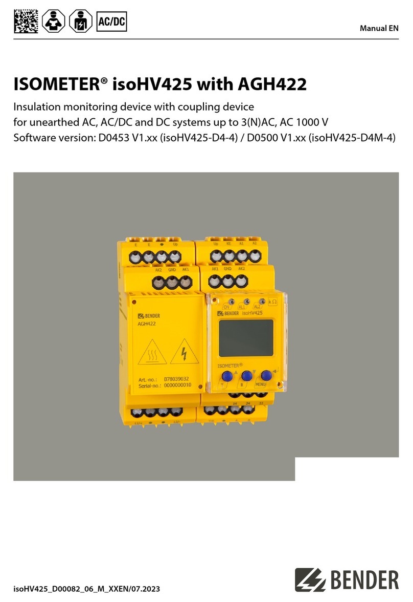
Bender ISOMETER isoHV425 User manual

Bender

Bender ISOMETER isoHV425 User manual

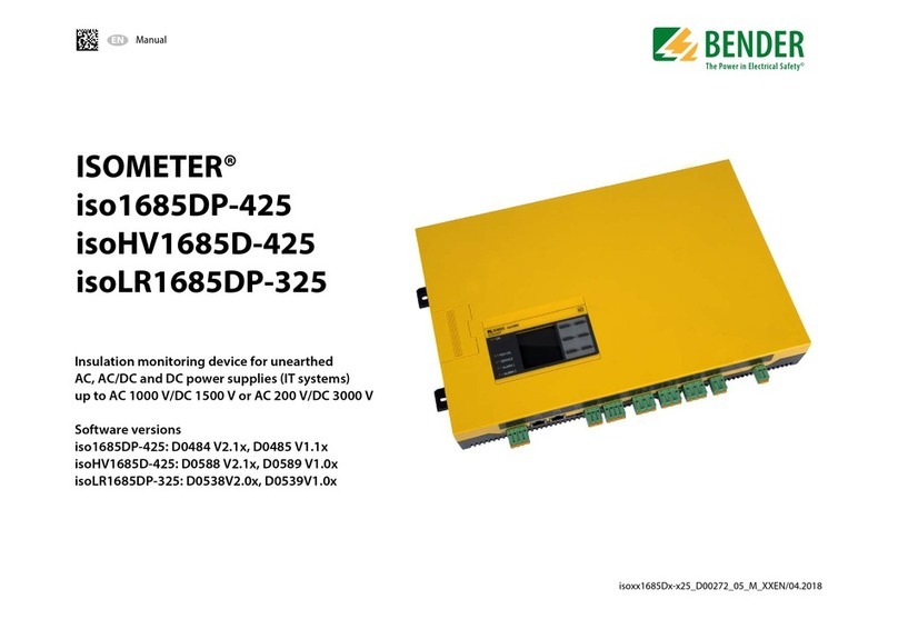
Bender ISOMETER iso1685DP-425 User manual

Bender

Bender ISOMETER iso1685DP-425 User manual

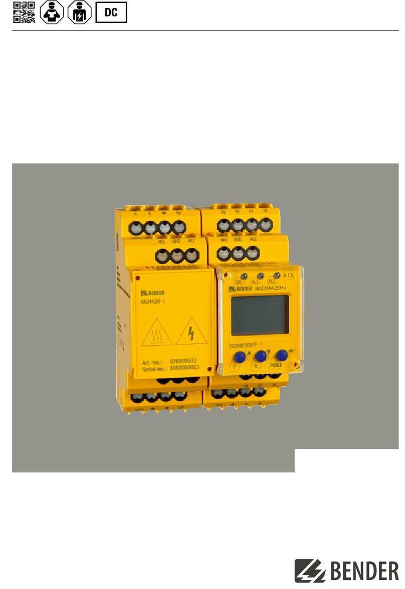
Bender ISOMETER isoCHA425HV User manual

Bender

Bender ISOMETER isoCHA425HV User manual

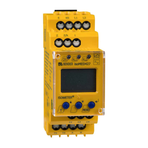
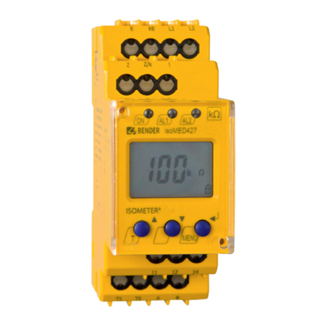
Bender isoMED427P User manual

Bender

Bender isoMED427P User manual

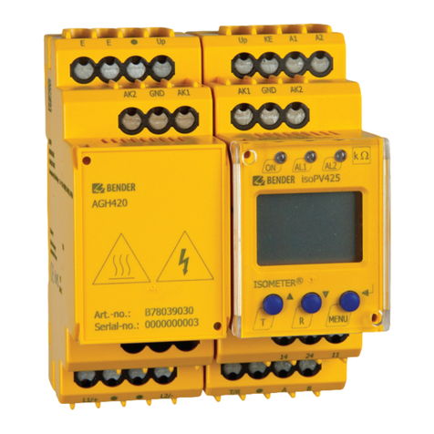
Bender ISOMETER isoPV425 with AGH420 User manual

Bender

Bender ISOMETER isoPV425 with AGH420 User manual

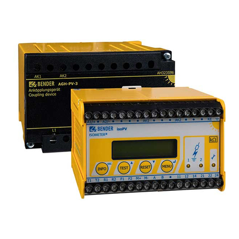
Bender ISOMETER isoPV with AGH-PV User manual

Bender

Bender ISOMETER isoPV with AGH-PV User manual

Bender ISOMETER isoGEN423 User manual

Bender

Bender ISOMETER isoGEN423 User manual

Bender ISOMETER iso1685DP-425 User manual

Bender

Bender ISOMETER iso1685DP-425 User manual

Bender CMD421 User manual

Bender

Bender CMD421 User manual

Bender ISOMETER isoRW685W-D User manual

Bender

Bender ISOMETER isoRW685W-D User manual

Bender ISOMETER isoHV425 User manual

Bender

Bender ISOMETER isoHV425 User manual

Bender PEM735 User manual

Bender

Bender PEM735 User manual

Bender RCMA421H User manual

Bender

Bender RCMA421H User manual

Bender RDC104 User manual

Bender

Bender RDC104 User manual

Bender LINETRAXX CTBS25 User manual

Bender

Bender LINETRAXX CTBS25 User manual

Bender RCMA423 User manual

Bender

Bender RCMA423 User manual

Bender ISOMETER isoES425 User manual

Bender

Bender ISOMETER isoES425 User manual

Bender COMTRAXX MK2430 User manual

Bender

Bender COMTRAXX MK2430 User manual

Bender RCMB-35-30 Series User manual

Bender

Bender RCMB-35-30 Series User manual

Bender W0-S20 User manual

Bender

Bender W0-S20 User manual

Bender isoMED427P-CX User manual

Bender

Bender isoMED427P-CX User manual

Bender RCMA423AS User manual

Bender

Bender RCMA423AS User manual

Bender ISOMETER isoCHA425 User manual

Bender

Bender ISOMETER isoCHA425 User manual

Bender ISOMETER iso685W-D User manual

Bender

Bender ISOMETER iso685W-D User manual

Popular Measuring Instrument manuals by other brands

microHAM SMORF manual

microHAM

microHAM SMORF manual

Futech WS6300 user manual

Futech

Futech WS6300 user manual

Dräger Multi-PID 2 user manual

Dräger

Dräger Multi-PID 2 user manual

GHM DeltaOHM LPPYRA05 operating manual

GHM

GHM DeltaOHM LPPYRA05 operating manual

Eaton 5775X-42X manual

Eaton

Eaton 5775X-42X manual

Additel ADT685Ex user manual

Additel

Additel ADT685Ex user manual

Targus AMP21AP user guide

Targus

Targus AMP21AP user guide

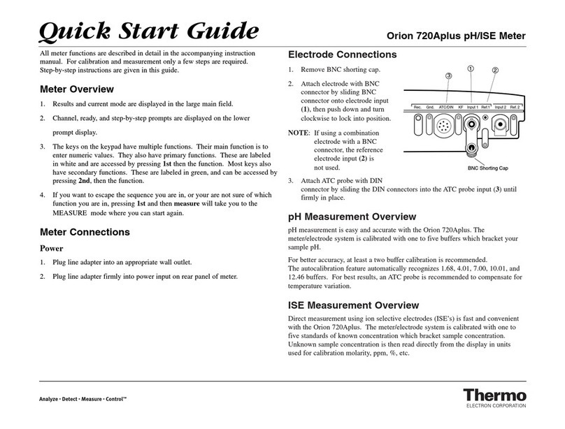
Thermo Scientific Orion 720Aplus quick start guide

Thermo Scientific

Thermo Scientific Orion 720Aplus quick start guide

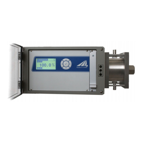
Opsytec Dr. Grobel FlowMissio-C manual

Opsytec Dr. Grobel

Opsytec Dr. Grobel FlowMissio-C manual

Fema Electronica LAP Series user manual

Fema Electronica

Fema Electronica LAP Series user manual

Grundfos AQC-D6 Installation and operating instructions

Grundfos

Grundfos AQC-D6 Installation and operating instructions

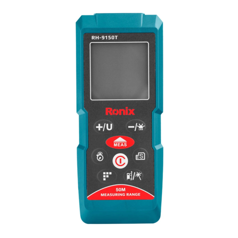
Ronix RH-9150T quick start guide

Ronix

Ronix RH-9150T quick start guide

FISCHER DS21xxxH series operating manual

FISCHER

FISCHER DS21xxxH series operating manual

ENERGY SUPPORT CORPORATION LP-30H instruction manual

ENERGY SUPPORT CORPORATION

ENERGY SUPPORT CORPORATION LP-30H instruction manual

Badger Meter 6200 user manual

Badger Meter

Badger Meter 6200 user manual

Silverline 482913 quick guide

Silverline

Silverline 482913 quick guide

Sonel MIC-10s1 operating manual

Sonel

Sonel MIC-10s1 operating manual

BW SENSING LEC315 Series Technical manual

BW SENSING

BW SENSING LEC315 Series Technical manual

manuals.online logo
manuals.online logoBrands
  • About & Mission
  • Contact us
  • Privacy Policy
  • Terms and Conditions

Copyright 2025 Manuals.Online. All Rights Reserved.