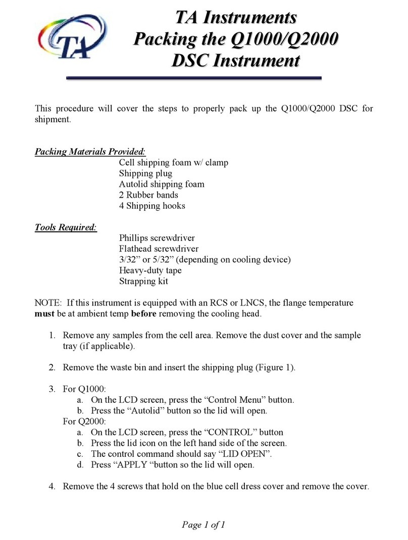
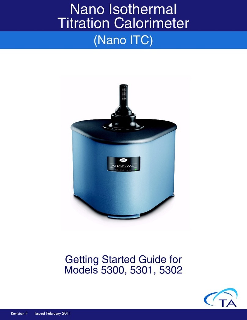
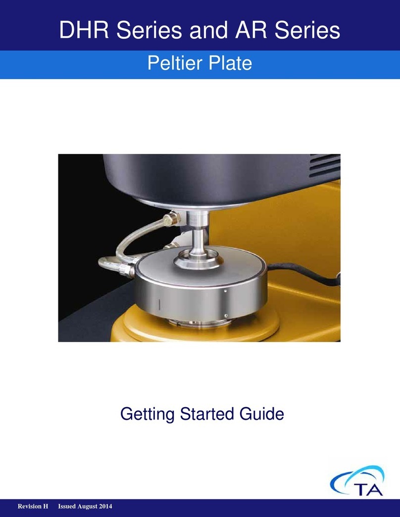
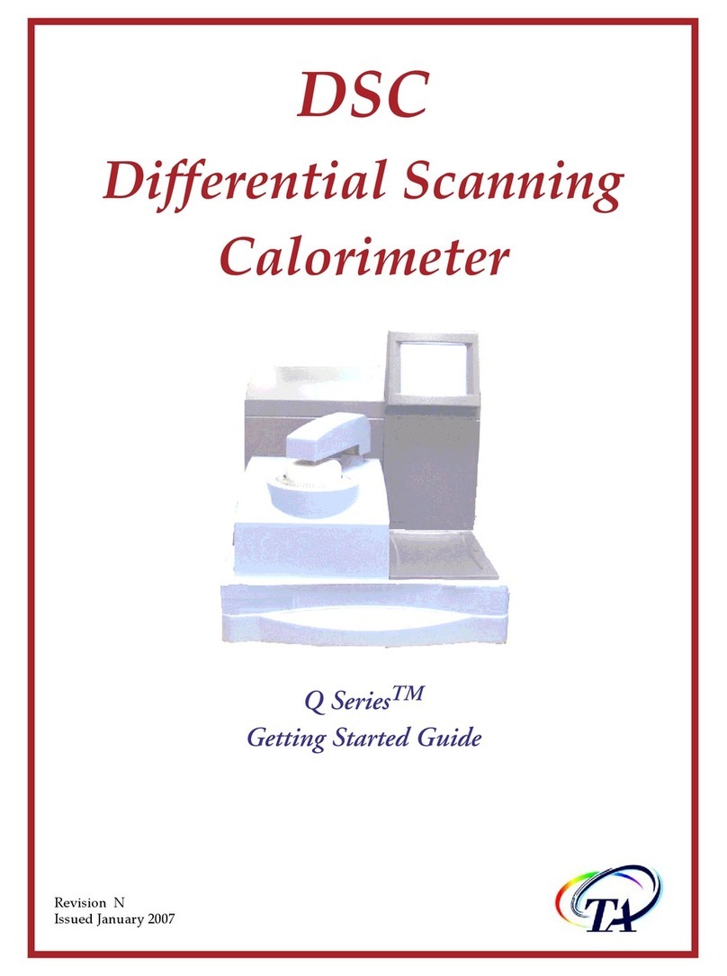
TA Instruments TGA5500 User manual

Getting Started Guide for
Models 55/550/5500
Revision CIssued February 2018
DISCOVERY TGA
THERMOGRAVIMETRIC ANALYZER

Discovery TGA™ Getting Started Guide Page 2
Notice
The material contained in this manual, and in the online help for the software used to support this instru-
ment, is believed adequate for the intended use of the instrument. If the instrument or procedures are used
for purposes other than those specified herein, confirmation of their suitability must be obtained from TA
Instruments. Otherwise, TA Instruments does not guarantee any results and assumes no obligation or
liability. TA Instruments also reserves the right to revise this document and to make changes without
notice.
TA Instruments may have patents, patent applications, trademarks, copyrights, or other intellectual prop-
erty covering subject matter in this document. Except as expressly provided in written license agreement
from TA Instruments, the furnishing of this document does not give you any license to these patents,
trademarks, copyrights, or other intellectual property.
TA Instruments Operating Software, as well as Module, Data Analysis, and Utility Software and their asso-
ciated manuals and online help, are proprietary and copyrighted by TA Instruments. Purchasers are granted
a license to use these software programs on the module and controller with which they were purchased.
These programs may not be duplicated by the purchaser without the prior written consent of TA Instru-
ments. Each licensed program shall remain the exclusive property of TA Instruments, and no rights or
licenses are granted to the purchaser other than as specified above.
TA Instruments can accept no liability for loss or damage, however caused, arising from the faulty or
incorrect use of its products.TA Instruments shall not be liable for any damages caused by interactions
between exogenous materials (e.g. chemicals) and parts of the instrument. This includes interactions of
gaseous, liquid or solid materials with parts of the instrument.
©2018 by
TA Instruments — Waters LLC
159 Lukens Drive
New Castle, DE 19720

Discovery TGA™ Getting Started Guide Page 3
Introduction
Important: TA Instruments Manual Supplement
Please click the TA Manual Supplement link to access the following important information supplemental
to this Getting Started Guide:
• TA Instruments Trademarks
• TA Instruments Patents
• Other Trademarks
• TA Instruments End-User License Agreement
• TA Instruments Offices

Discovery TGA™ Getting Started Guide Page 4
Notes, Cautions, and Warnings
This manual uses NOTES, CAUTIONS, and WARNINGS to emphasize important and critical
instructions. In the body of the manual these may be found in the shaded box on the outside of the page.
NOTE: A NOTE highlights important information about equipment or procedures.
CAUTION: A CAUTION emphasizes a procedure that may damage equipment or cause loss of data
if not followed correctly.
MISE EN GARDE: UNE MISE EN GARDE met l'accent sur une procédure susceptible d'endom-
mager l'équipement ou de causer la perte des données si elle n'est pas correctement suivie.
Regulatory Compliance
Safety Standards
For Canada
CAN/CSA-C22.2 No. 61010-1-12 Safety requirements for electrical equipment for measurement, control,
and laboratory use, Part 1: General Requirements.
CAN/CSA-C22.2 No. 61010-2-010-04 Particular requirements for laboratory equipment for the heating of
materials.
CAN/CSA-C22.2 No. 61010-2-081-04 Particular requirements for automatic and semi-automatic labora-
tory equipment for analysis and other purposes.
For European Economic Area
(In accordance with Council Directive 2014/35/EU of the European Parliament and of the Council of 26
February 2014 on the harmonization of the laws of the Member States relating to the making available on
the market of electrical equipment designed for use within certain voltage limits.)
EN 61010-1:2010 Safety requirements for electrical equipment for measurement, control, and laboratory
use, Part 1: General Requirements.
EN 61010-2-010:2014 Particular requirements for laboratory equipment for the heating of materials.
EN 61010-2-081:2015 Particular requirements for automatic and semi-automatic laboratory equipment for
analysis and other purposes.
A WARNING indicates a procedure that may be hazardous to the operator or to the environment
if not followed correctly.
Un AVERTISSEMENT indique une procédure qui peut être dangereuse pour l'opérateur ou l'envi-
ronnement si elle n'est pas correctement suivie.

Discovery TGA™ Getting Started Guide Page 5
For United States
UL61010-1:2012 Electrical Equipment for Laboratory Use; Part 1: General Requirements.
UL61010-2-010:2015 Particular requirements for laboratory equipment for the heating of materials.
UL 61010-2-081:2015 Particular requirements for automatic and semi-automatic laboratory equipment for
analysis and other purposes.
Electromagnetic Compatibility Standards
For Australia and New Zealand
AS/NZS CISPR11:2015 Limits and methods of measurement of electronic disturbance characteristics of
industrial, scientific and medical (ISM) radio frequency equipment.
For Canada
ICES-001 Issue 4 June 2006 Interference-Causing Equipment Standard: Industrial, Scientific, and Medical
Radio Frequency Generators.
For the European Economic Area
(In accordance with Council Directive 2014/30/EC of the European Parliament and of the Council of 26
February 2014 on the harmonization of the laws of the Member States relating to electromagnetic
compatibility.)
EN61326-1: 2013 Electrical equipment for measurement, control, and laboratory use - EMC requirements
- Part 1: General requirements, Table 3 - Immunity test requirements for equipment used in controlled EM
environments, Emission requirements for Group 1, Class A equipment.
For the United States
CFR Title 47 Telecommunication Chapter I Federal Communications Commission, Part 15 Radio
frequency devices (FCC regulation pertaining to radio frequency emissions).
CAUTION: This equipment is not intended for use in residential environments and may not provide
adequate protection to radio reception in such environments.
MISE EN GARDE: Cet appareil n'a pas destiné à être utilisé dans des environnements résidentiels et
ne peut pas fournir une protection adéquate à la réception radio dans de tels environnements.

Discovery TGA™ Getting Started Guide Page 6
Safety
Instrument Symbols
The following labels are displayed on the Discovery TGA system for your protection:
Please heed the warning labels and take the necessary precautions when dealing with those parts of the
instrument. The Discovery TGA Getting Started Guide contains cautions and warnings that must be
followed for your own safety.
WARNING: The operator of this instrument is advised that if the equipment is used in a manner
not specified in this manual, the protection provided by the equipment may be impaired.
AVERTISSEMENT: L'utilisateur de cet instrument est prévenu qu'en cas d'utilisation contraire
aux indications du manuel, la protection offerte par l'équipement peut être altérée.
Symbol Explanation
This symbol indicates that you should read this Getting Started Guide for impor-
tant safety information. This guide contains important warnings and cautions
related to the installation, operation, and safety of the Discovery TGA system.
If you are not trained in electrical procedures, do not remove the cabinet covers
unless specifically instructed to do so in the manual. Maintenance and repair of
internal parts must be performed only by TA Instruments or other qualified
service personnel.
Ce symbole indique que vous devez lire entièrement ce guide de démarrage
pour obtenir d'importantes informations relatives à sécurité. Ce guide contient
d'importants avertissements et mises en garde relatifs à l'installation, à l'utilisa-
tion et à la sécurité du système Discovery TGA.
Si vous n'êtes pas formé aux procédures électriques, ne déposez pas les couver-
cles de l'armoire sauf indications spécifiques contenues dans le manuel. La
maintenance et la réparation des pièces internes doivent être effectuées unique-
ment par TA Instruments ou tout autre personnel d'entretien qualifié.
This symbol indicates that a hot surface may be present. Take care not to touch
this area or allow any material that may melt or burn come in contact with this
hot surface.
Ce symbole indique la présence possible d'une surface chaude. Prenez soin de
ne pas toucher cette zone ou de laisser un matériau susceptible de fondre ou de
brûler entrer en contact avec cette surface chaude.

Discovery TGA™ Getting Started Guide Page 7
Electrical Safety
You must unplug the instrument before doing any maintenance or repair work; voltages as high as
120/240 VAC are present in the instrument.
Chemical Safety
Thermal Safety
DANGER: Risk of electric shock. High voltages are present in this instrument. Maintenance and
repair of internal parts must be performed only by TA Instruments or other qualified service per-
sonnel.
DANGER: Risque de choc électrique. Présence de tensions élevées dans cet instrument. La
maintenance et la réparation des pièces internes doivent être effectuées uniquement par TA
Instruments ou tout autre personnel d'entretien qualifié.
WARNING: Protective earthing is provided through the mains power cord. Use of a grounded
mains power outlet is required.
AVERTISSEMENT: Mise à la terre de protection est assurée par le cordon d'alimentation secteur.
Utilisation d'une prise d'alimentation secteur terre est nécessaire.
WARNING: Do not use hydrogen or any other explosive gas in the TGA furnace.
AVERTISSEMENT: N'utilisez pas d'hydrogène ou tout autre gaz explosif dans le four TGA.
WARNING: Oxygen can be used as a purge gas in the TGA. However, the furnace must be kept
clean so that volatile hydrocarbons, which may combust, are removed.
AVERTISSEMENT: L'oxygène peut être utilisé comme gaz de drainage dans le TGA. Toutefois le
four doit rester propre pour que les hydrocarbures volatils, qui peuvent brûler, soient éliminés.
WARNING: If you are using samples that may emit harmful gases, attach a compatible tube to
the purge gas exit to transfer the gas to an exhaust or other suitable protective device.
AVERTISSEMENT: Si vous utilisez des échantillons qui émettent des gaz nocifs, fixez un tuyau
compatible à la sortie du gaz de drainage pour transférer le gaz vers un échappement ou vers
tout autre dispositif de protection approprié.
WARNING: After running an experiment, allow the open furnace and thermocouple to cool down
before you touch them. Allow the furnace to cool down before removing the lower furnace (ther-
mocouple) assembly of the 5500.
AVERTISSEMENT: Après une expérience, laissez le four ouvert et le thermocouple refroidir
avant de les toucher. Laissez le four refroidir avant de déposer l'ensemble du four inférieur
(thermocouple) assemblage de la 5500.

Discovery TGA™ Getting Started Guide Page 8
Mechanical Safety
Lifting the Instrument
The Discovery TGA is a heavy instrument. In order to avoid injury, particularly to the back, please follow
this advice:
WARNING: Keep your fingers and all other objects out of the path of the furnace when it is mov-
ing. The seal is very tight.
AVERTISSEMENT: Écartez vos doigts et tous les autres objets du chemin du four lorsqu'il est en
mouvement. L'étanchéité est très hermétique.
WARNING: Use two people to lift and/or carry the instrument. The instrument is too heavy for
one person to handle safely.
AVERTISSEMENT: Demandez à deux personnes de soulever et/ou de porter l'instrument.
L'instrument est trop lourd pour qu'une seule personne le manipule en toute sécurité.

Discovery TGA™ Getting Started Guide Page 9
Table of Contents
Introduction ...................................................................................................................................................... 3
Important: TA Instruments Manual Supplement . . . . . . . . . . . . . . . . . . . . . . . . . . . . . . . . . . . . . . . . . 3
Notes, Cautions, and Warnings . . . . . . . . . . . . . . . . . . . . . . . . . . . . . . . . . . . . . . . . . . . . . . . . . . . . . . . 4
Regulatory Compliance . . . . . . . . . . . . . . . . . . . . . . . . . . . . . . . . . . . . . . . . . . . . . . . . . . . . . . . . . . . . . 4
Safety Standards . . . . . . . . . . . . . . . . . . . . . . . . . . . . . . . . . . . . . . . . . . . . . . . . . . . . . . . . . . . . . . . 4
Electromagnetic Compatibility Standards . . . . . . . . . . . . . . . . . . . . . . . . . . . . . . . . . . . . . . . . . . . . . . . 5
Safety . . . . . . . . . . . . . . . . . . . . . . . . . . . . . . . . . . . . . . . . . . . . . . . . . . . . . . . . . . . . . . . . . . . . . . . . . . . 6
Instrument Symbols . . . . . . . . . . . . . . . . . . . . . . . . . . . . . . . . . . . . . . . . . . . . . . . . . . . . . . . . . . . . 6
Electrical Safety . . . . . . . . . . . . . . . . . . . . . . . . . . . . . . . . . . . . . . . . . . . . . . . . . . . . . . . . . . . . . . . 7
Chemical Safety . . . . . . . . . . . . . . . . . . . . . . . . . . . . . . . . . . . . . . . . . . . . . . . . . . . . . . . . . . . . . . . 7
Thermal Safety . . . . . . . . . . . . . . . . . . . . . . . . . . . . . . . . . . . . . . . . . . . . . . . . . . . . . . . . . . . . . . . . 7
Mechanical Safety . . . . . . . . . . . . . . . . . . . . . . . . . . . . . . . . . . . . . . . . . . . . . . . . . . . . . . . . . . . . . 8
Lifting the Instrument . . . . . . . . . . . . . . . . . . . . . . . . . . . . . . . . . . . . . . . . . . . . . . . . . . . . . . . . . . . 8
Chapter 1:
Introducing the Discovery TGA ................................................................................................ 12
Overview . . . . . . . . . . . . . . . . . . . . . . . . . . . . . . . . . . . . . . . . . . . . . . . . . . . . . . . . . . . . . . . . . . . . . . . . . . 12
TGA System Components . . . . . . . . . . . . . . . . . . . . . . . . . . . . . . . . . . . . . . . . . . . . . . . . . . . . . . . . . . . . . 13
Balance Assembly . . . . . . . . . . . . . . . . . . . . . . . . . . . . . . . . . . . . . . . . . . . . . . . . . . . . . . . . . . . . 13
Wire-Wound Furnace for TGA 55 and TGA 550 . . . . . . . . . . . . . . . . . . . . . . . . . . . . . . . . . . . . 14
EGA Furnace for TGA 55 and TGA 550 . . . . . . . . . . . . . . . . . . . . . . . . . . . . . . . . . . . . . . . . . . . 15
Infrared (IR) Furnace for TGA 5500 . . . . . . . . . . . . . . . . . . . . . . . . . . . . . . . . . . . . . . . . . . . . . . 16
Discovery TGA Autoloader or Autosampler . . . . . . . . . . . . . . . . . . . . . . . . . . . . . . . . . . . . . . . . 17
Hi-Res™ TGA . . . . . . . . . . . . . . . . . . . . . . . . . . . . . . . . . . . . . . . . . . . . . . . . . . . . . . . . . . . . . . . 18
Modulated TGA™ (MTGA™) . . . . . . . . . . . . . . . . . . . . . . . . . . . . . . . . . . . . . . . . . . . . . . . . . . 19
Other Discovery TGA Accessories . . . . . . . . . . . . . . . . . . . . . . . . . . . . . . . . . . . . . . . . . . . . . . . 19
The Discovery TGA User Interface . . . . . . . . . . . . . . . . . . . . . . . . . . . . . . . . . . . . . . . . . . . . . . . . . . . . . . 20
Primary Function Buttons . . . . . . . . . . . . . . . . . . . . . . . . . . . . . . . . . . . . . . . . . . . . . . . . . . . . . . . . . . 21
View Panel . . . . . . . . . . . . . . . . . . . . . . . . . . . . . . . . . . . . . . . . . . . . . . . . . . . . . . . . . . . . . . . . . . . . . 22
Additional Function Buttons . . . . . . . . . . . . . . . . . . . . . . . . . . . . . . . . . . . . . . . . . . . . . . . . . . . . . . . . 23
Instrument Specifications . . . . . . . . . . . . . . . . . . . . . . . . . . . . . . . . . . . . . . . . . . . . . . . . . . . . . . . . . . . . . 24
Discovery TGA Instrument Characteristics . . . . . . . . . . . . . . . . . . . . . . . . . . . . . . . . . . . . . . . . . . . . 24
Discovery TGA Sampling System . . . . . . . . . . . . . . . . . . . . . . . . . . . . . . . . . . . . . . . . . . . . . . . . . . . 25
Chapter 2:
Installing the Discovery TGA System ...................................................................................... 26
Unpacking/Repacking the TGA . . . . . . . . . . . . . . . . . . . . . . . . . . . . . . . . . . . . . . . . . . . . . . . . . . . . . . . . 26
Installing the Discovery TGA System . . . . . . . . . . . . . . . . . . . . . . . . . . . . . . . . . . . . . . . . . . . . . . . . . . . . 26
Inspecting the System . . . . . . . . . . . . . . . . . . . . . . . . . . . . . . . . . . . . . . . . . . . . . . . . . . . . . . . . . . . . . 27
Choosing a Location . . . . . . . . . . . . . . . . . . . . . . . . . . . . . . . . . . . . . . . . . . . . . . . . . . . . . . . . . . . . . . 27
In . . . . . . . . . . . . . . . . . . . . . . . . . . . . . . . . . . . . . . . . . . . . . . . . . . . . . . . . . . . . . . . . . . . . . . . . . . 27
On . . . . . . . . . . . . . . . . . . . . . . . . . . . . . . . . . . . . . . . . . . . . . . . . . . . . . . . . . . . . . . . . . . . . . . . . . 27
Near . . . . . . . . . . . . . . . . . . . . . . . . . . . . . . . . . . . . . . . . . . . . . . . . . . . . . . . . . . . . . . . . . . . . . . . 27
Away from . . . . . . . . . . . . . . . . . . . . . . . . . . . . . . . . . . . . . . . . . . . . . . . . . . . . . . . . . . . . . . . . . . 27
Preparing the Discovery TGA for Installation . . . . . . . . . . . . . . . . . . . . . . . . . . . . . . . . . . . . . . . . . . 28
Removing the Shipping Bracket . . . . . . . . . . . . . . . . . . . . . . . . . . . . . . . . . . . . . . . . . . . . . . . . . . 28
Unpacking the Balance . . . . . . . . . . . . . . . . . . . . . . . . . . . . . . . . . . . . . . . . . . . . . . . . . . . . . . . . . 29

Discovery TGA™ Getting Started Guide Page 10
Connecting the Discovery TGA to the Controller . . . . . . . . . . . . . . . . . . . . . . . . . . . . . . . . . . . . . . . 31
Setting Up System Communication . . . . . . . . . . . . . . . . . . . . . . . . . . . . . . . . . . . . . . . . . . . . . . . . . . 33
Connecting Lines to the Gas Delivery Module . . . . . . . . . . . . . . . . . . . . . . . . . . . . . . . . . . . . . . . . . . 33
Connecting Purge Gas Lines . . . . . . . . . . . . . . . . . . . . . . . . . . . . . . . . . . . . . . . . . . . . . . . . . . . . 33
Connecting the Air Cool Line . . . . . . . . . . . . . . . . . . . . . . . . . . . . . . . . . . . . . . . . . . . . . . . . . . . 35
Connecting the Heat Exchanger Cable and Water Hoses . . . . . . . . . . . . . . . . . . . . . . . . . . . . . . . . . . 36
Connecting the Power Cable . . . . . . . . . . . . . . . . . . . . . . . . . . . . . . . . . . . . . . . . . . . . . . . . . . . . . . . . 37
Installing the Autosampler Tray . . . . . . . . . . . . . . . . . . . . . . . . . . . . . . . . . . . . . . . . . . . . . . . . . . . . . 37
Installing the Hang-Down Wires . . . . . . . . . . . . . . . . . . . . . . . . . . . . . . . . . . . . . . . . . . . . . . . . . . . . 38
Installing the Tare Hang-Down Wire . . . . . . . . . . . . . . . . . . . . . . . . . . . . . . . . . . . . . . . . . . . . . . 38
Installing the Upper Reflective Assembly and Sample Hang-Down Wire on the TGA 5500 . . . 40
Installing the Sample Hang-Down Wire on the TGA 55 and TGA 550 . . . . . . . . . . . . . . . . . . . 44
Leveling the Discovery TGA and Aligning the Balance . . . . . . . . . . . . . . . . . . . . . . . . . . . . . . . . . . 45
Leveling the Instrument . . . . . . . . . . . . . . . . . . . . . . . . . . . . . . . . . . . . . . . . . . . . . . . . . . . . . . . . 45
Aligning the Sample Hang-Down Wire . . . . . . . . . . . . . . . . . . . . . . . . . . . . . . . . . . . . . . . . . . . . 45
Aligning the Bottom of the Sample Hang-Down Wire . . . . . . . . . . . . . . . . . . . . . . . . . . . . . . . . 47
Installing the Lower Furnace Assembly on the TGA 5500 . . . . . . . . . . . . . . . . . . . . . . . . . . . . . . . . 48
Closing the Balance Assembly . . . . . . . . . . . . . . . . . . . . . . . . . . . . . . . . . . . . . . . . . . . . . . . . . . . . . . 51
Balance Conditioning . . . . . . . . . . . . . . . . . . . . . . . . . . . . . . . . . . . . . . . . . . . . . . . . . . . . . . . . . . . . . 51
Filling the Heat Exchanger Reservoir . . . . . . . . . . . . . . . . . . . . . . . . . . . . . . . . . . . . . . . . . . . . . . . . . 51
Purging Air from the Heat Exchanger System . . . . . . . . . . . . . . . . . . . . . . . . . . . . . . . . . . . . . . . . . . 52
Installing the Autosampler Tray . . . . . . . . . . . . . . . . . . . . . . . . . . . . . . . . . . . . . . . . . . . . . . . . . . . . . 53
Starting the Discovery TGA System . . . . . . . . . . . . . . . . . . . . . . . . . . . . . . . . . . . . . . . . . . . . . . . . . . . . . 54
Shutting Down the Discovery TGA . . . . . . . . . . . . . . . . . . . . . . . . . . . . . . . . . . . . . . . . . . . . . . . . . . . . . 55
Chapter 3:
Use, Maintenance, & Diagnostics ............................................................................................. 56
Using the Discovery TGA . . . . . . . . . . . . . . . . . . . . . . . . . . . . . . . . . . . . . . . . . . . . . . . . . . . . . . . . . . . . . 56
Before You Begin . . . . . . . . . . . . . . . . . . . . . . . . . . . . . . . . . . . . . . . . . . . . . . . . . . . . . . . . . . . . . . . . 56
Calibrating the Discovery TGA . . . . . . . . . . . . . . . . . . . . . . . . . . . . . . . . . . . . . . . . . . . . . . . . . . . . . . . . . 57
Autosampler and Autoloader Calibration . . . . . . . . . . . . . . . . . . . . . . . . . . . . . . . . . . . . . . . . . . . . . . 57
Weight Calibration . . . . . . . . . . . . . . . . . . . . . . . . . . . . . . . . . . . . . . . . . . . . . . . . . . . . . . . . . . . . . . . 57
Temperature Calibration . . . . . . . . . . . . . . . . . . . . . . . . . . . . . . . . . . . . . . . . . . . . . . . . . . . . . . . . . . . 58
Running a Discovery TGA Experiment . . . . . . . . . . . . . . . . . . . . . . . . . . . . . . . . . . . . . . . . . . . . . . . . . . 59
Selecting the Pan Size and Material . . . . . . . . . . . . . . . . . . . . . . . . . . . . . . . . . . . . . . . . . . . . . . . . . . 59
Taring the Sample Pan(s) . . . . . . . . . . . . . . . . . . . . . . . . . . . . . . . . . . . . . . . . . . . . . . . . . . . . . . . . . . 59
Loading the Sample Pans . . . . . . . . . . . . . . . . . . . . . . . . . . . . . . . . . . . . . . . . . . . . . . . . . . . . . . . . . . 60
Loading Open Pans . . . . . . . . . . . . . . . . . . . . . . . . . . . . . . . . . . . . . . . . . . . . . . . . . . . . . . . . . . . . 60
Loading Sealed Pans . . . . . . . . . . . . . . . . . . . . . . . . . . . . . . . . . . . . . . . . . . . . . . . . . . . . . . . . . . . 60
Starting an Experiment . . . . . . . . . . . . . . . . . . . . . . . . . . . . . . . . . . . . . . . . . . . . . . . . . . . . . . . . . . . . 61
Stopping an Experiment . . . . . . . . . . . . . . . . . . . . . . . . . . . . . . . . . . . . . . . . . . . . . . . . . . . . . . . . . . . 61
Removing or Reinstalling a Wire-wound or EGA Furnace . . . . . . . . . . . . . . . . . . . . . . . . . . . . . . . . . . . . 61
Furnace Removal . . . . . . . . . . . . . . . . . . . . . . . . . . . . . . . . . . . . . . . . . . . . . . . . . . . . . . . . . . . . . . . . 61
Furnace Installation . . . . . . . . . . . . . . . . . . . . . . . . . . . . . . . . . . . . . . . . . . . . . . . . . . . . . . . . . . . . . . . 62
Maintaining the Instrument . . . . . . . . . . . . . . . . . . . . . . . . . . . . . . . . . . . . . . . . . . . . . . . . . . . . . . . . . . . . 63
Conditioning the Balance . . . . . . . . . . . . . . . . . . . . . . . . . . . . . . . . . . . . . . . . . . . . . . . . . . . . . . . . . . 63
Cleaning the Furnace . . . . . . . . . . . . . . . . . . . . . . . . . . . . . . . . . . . . . . . . . . . . . . . . . . . . . . . . . . . . . . 63
Cleaning the Pans . . . . . . . . . . . . . . . . . . . . . . . . . . . . . . . . . . . . . . . . . . . . . . . . . . . . . . . . . . . . . . . . 64
Cleaning the User Interface Screen . . . . . . . . . . . . . . . . . . . . . . . . . . . . . . . . . . . . . . . . . . . . . . . . . . . 64

Discovery TGA™ Getting Started Guide Page 11
Replacing Fuses . . . . . . . . . . . . . . . . . . . . . . . . . . . . . . . . . . . . . . . . . . . . . . . . . . . . . . . . . . . . . . . . . 65
Maintaining the Heat Exchanger . . . . . . . . . . . . . . . . . . . . . . . . . . . . . . . . . . . . . . . . . . . . . . . . . . . . . . . . 65
Replacement Parts . . . . . . . . . . . . . . . . . . . . . . . . . . . . . . . . . . . . . . . . . . . . . . . . . . . . . . . . . . . . . . . . . . . 66

Discovery TGA™ Getting Started Guide Page 12
Chapter 1:
Introducing the Discovery TGA
Overview
Your TA Instruments Discovery Thermogravimetric Analyzer (Discovery TGA) is used in conjunction
with a controller computer and associated software to make up a thermal analysis system.
The Discovery TGA measures the amount and rate of weight change in a material, either as a function of
increasing temperature or isothermally as a function of time, in a controlled atmosphere. The TGA can be
used to characterize any material that exhibits a weight change and to detect phase changes due to decom-
position, oxidation, or dehydration. This information helps the scientist or engineer identify the percent
weight change and correlate chemical structure, processing, and end-use performance.
Your controller is a computer that performs the following functions:
• Provides an interface between you and the analysis instrument
• Enables you to set up experiments and enter parameters
• Stores experimental data
• Runs data analysis programs.
Figure 1 Discovery TGA system (TGA 5500 shown).
NOTE: For technical reference information, theory of operation, and other information associated with the
TGA not found in this manual, see TRIOS software Online Help.

Discovery TGA™ Getting Started Guide Page 13
TGA System Components
The Discovery TGA is comprised of the following major hardware components:
• The Tru-Mass™ balance, which provides precise measurement of sample weight. The balance is the
key to the TGA system.
• The heating system, or furnace (wire-wound for TGA 55 and TGA 550, infrared for TGA 5500),
which controls the sample temperature.
• The Autoloader or Autosampler, which loads and unloads the sample to and from the balance. The
Autosampler platform has a built-in pan punching mechanism (standard on the TGA 5500 and optional
on the TGA 550) that is used in conjunction with the optional sealed aluminum pans (also standard on
the TGA 5500 and optional on the TGA 550).
• The heat exchanger, which dissipates heat from the furnace.
• The gas delivery module (GDM), which controls the purge gas to the balance and furnace.
The next few pages briefly describe the components of the TGA.
Balance Assembly
The TGA balance assembly is a null balance system consisting of the balance meter movement, the bal-
ance arm, the balance position sensor, the hang-down wire assemblies, the sample pan, and the tare pan.
• The balance meter movement is a taut-band meter movement to which the balance arm is attached.
• The balance arm is an assembly constructed of beryllium copper alloy attached to the meter move-
ment.
• The balance position sensor is comprised of an LED source and a pair of photodiodes on printed circuit
boards that detect the null position of the meter movement.
The TGA has two hang-down wire assemblies: one for the tare pan and one for the sample pan. Each
assembly consists of a hang-down wire and beryllium copper decoupler loop. The hang-down wire has
hooks on each end used to connect the pan to the loop. The loop connects the hang-down wire to the
balance arm. The longer hang-down wire is for the sample side.
The tare hang-down wire, tare pan, and any counterbalance weight mechanically balances the weight of the
sample pan and sample hang-down wire.

Discovery TGA™ Getting Started Guide Page 14
Wire-Wound Furnace for TGA 55 and TGA 550
The wire-wound furnace comes installed on the Discovery TGA 55 and TGA 550. The wire-wound and
EGA furnaces can be exchanged as directed in the Online Help. The wire-wound furnace is a resistance
heater wound on alumina ceramic, which allows sample zone temperatures as high as 1,000°C with heat-
ing rates up to 100°C/min. The housing is mounted to a furnace base that raises and lowers the furnace for
sample loading and unloading. A Platinel II® thermocouple is positioned in the furnace, just above the
sample pan, where it monitors the sample environment temperature.
Figure 2 Wire-wound furnace cut-away diagram.

Discovery TGA™ Getting Started Guide Page 15
EGA Furnace for TGA 55 and TGA 550
The Evolved Gas Analysis (EGA) furnace is an optional accessory for the Discovery TGA 55 and TGA
550 that allows you to connect a spectrometer to the instrument so that the gases evolved by sample
decomposition can be analyzed. The EGA furnace and the Wire-wound furnace can be exchanged as
directed in the Online Help.
Figure 3 EGA furnace cut-away diagram.
The EGA furnace consists of a quartz glass sample tube surrounded by an electric resistance heater, both of
which are contained within a water-cooled furnace housing. The housing is mounted to a furnace base that
raises and lowers the furnace for sample loading and unloading.
The sample tube has a purge gas inlet that passes through the right side of the furnace housing. A fitting on
the left side of the housing allows connection of a transfer line to carry exhaust gas to a spectrometer such
as a mass spectrometer. Because the heater is external to the sample tube, evolved gases from sample
decomposition within the sample tube do not come in contact with the resistance elements or the furnace
ceramic refractory.
Cooling air enters through the furnace base and passes upward between the outside of the sample tube and
the inside of the furnace, completely separating the cooling air from the sample and the sample zone. The
furnace is a resistance heater wound on alumina ceramic, which allows sample zone temperatures as high
as 1000°C with heating rates up to 50°C/min. A Platinel II® thermocouple is positioned in the furnace, just
above the sample pan, where it monitors the sample environment temperature.
The furnace base moves the furnace assembly up around the sample pan to the closed position, or down
away from the sample pan to the open position.
Quartz tube
Water-cooled furnace housing
Electric resistance heater
Furnace base

Discovery TGA™ Getting Started Guide Page 16
Infrared (IR) Furnace for TGA 5500
The IR furnace (shown below) uses quartz halogen lamps as the heat source. Four lamps are arranged in a
circular pattern surrounding the quartz tube that encloses the sample area. Infrared energy from the lamps
is directed toward the sample area by a water-cooled, gold-plated reflector consisting of four elliptical
surfaces.
The sample area is enclosed by a cylinder inside of the quartz tube. This cylinder absorbs radiation from
the lamps and heats the sample, pan, and thermocouple.
Figure 4 IR furnace cut-away diagram.
Temperature is measured and controlled by a thermocouple assembly under the sample pan. The thermo-
couple assembly includes a second independent thermocouple to protect the furnace from excessive
temperature.
Heat shield assemblies above and below the energy-absorbing tube reduce heat losses from the ends of the
furnace.
Purge gas enters the sample area through a tube within the quartz tube, passes through a hole in the wall of
the absorber across the top of the sample pan, through another hole in the wall of the absorber, and exits via
a second tube in the quartz tube.
A magnetic coil surrounding the furnace generates a field that acts on magnetic samples in the sample pan.
This facilitates automated temperature calibration using Curie point standards and Curie point studies.
Rapid cooling of the furnace at the end of an experiment is facilitated by air that enters the furnace cham-
ber through the bottom of the furnace.
Heat shields
Sample pan
Purge gas outlet
Thermocouple
Energy-absorbing
Purge gas inlet
Quartz tube
cylinder

Discovery TGA™ Getting Started Guide Page 17
Discovery TGA Autoloader or Autosampler
Autoloader
The TGA 55 and TGA 550 come standard with an Autoloader (shown below) that automatically loads the
pan at the touch of a button or at the start of the run. On the TGA 550 the Autoloader can be upgraded to
the Autosampler.
Figure 5 Autoloader.
To calibrate the Autoloader, refer to TRIOS Online Help.
Autosampler
The Discovery TGA Autosampler (shown below) allows you to place multiple samples on the platform for
automatic loading and run sequencing. Using the standard pan tray, up to 25 samples can be accommo-
dated. Experiments are performed as normal, but samples can be run on a continual basis.
See “Discovery TGA Sampling System” on page 25 for the pans that can be used with the Discovery TGA
Autosampler:
Figure 6 Discovery TGA Autosampler (Discovery TGA 550 shown).

Discovery TGA™ Getting Started Guide Page 18
The sample can be sealed in a special aluminum pan and opened (exposed to the environment) immedi-
ately before being loaded into the balance via the Autosampler’s optional punching mechanism. The
punching mechanism ensures that only punched pans are loaded onto the balance. If punching is not suc-
cessful, the pan will not be loaded.
Figure 7 Optional punching mechanism.
To calibrate the sample tray and punching mechanism, refer to “Calibrating the Discovery TGA” on
page 57 of this manual and TRIOS Online Help.
Hi-Res™ TGA
The TA Instruments Hi-Res™TGA technique differs from alternative control techniques in that the heating
rate of the sample material is dynamically and continuously modified in response to changes in the rate of
decomposition of the sample so as to optimize both weight change resolution and time of analysis. This
TGA technique (supplied with the Discovery TGA 5500, available as an upgrade for TGA 550) allows the
use of very high heating rates in baseline regions where no weight changes are occurring, but automatically
slows the heating rate during weight changes. Once the weight change(s) are complete, the system returns
to the selected ramp heating rate. Typical Hi-Res ramps often take the same or less time to complete than a
comparable constant heating rate experiment run at a lower heating rate, while providing improved resolu-
tion.
Some of the benefits provided by the Hi-Res option are:
• Improved transition resolution
• Faster scans
• Enhanced signature analysis capability
• Transition temperatures closer to isothermal values
• Increased method programming versatility

Discovery TGA™ Getting Started Guide Page 19
Modulated TGA™ (MTGA™)
TA Instruments Modulated TGA (MTGA) is an innovative option that is used with Thermogravimetric
Analyzers. This option is used to study the same decomposition or volatilization properties as conventional
TGA. However, MTGA provides unique capabilities that increase the amount of information obtained
from a single TGA experiment, thereby improving the quality of interpretation.
These unique capabilities include:
• continuous determination of activation energy
• verification of single kinetic mechanism
• verification of first-order kinetic model.
MTGA is an enhancement of TGA that provides the same information as traditional TGA, plus new infor-
mation that permits unique insights into the behavior of the weight loss reaction.
Specifically, MTGA provides an alternative way to obtain kinetic information about one or more weight
losses, in a shorter period of time than the multiple heating rate approach.
In addition, MTGA provides continuous determined values for activation energy throughout the weight
loss reaction, not just at specific reaction levels. The ability to obtain activation energy continuously allows
you to follow changes in the activation energy during the reaction, as a function of temperature or
conversion. The calculation of activation energy is “model free” – no knowledge about the form of the
kinetic equation is required.
The assumption of a first-order kinetic model (a reasonable assumption for many decomposition
reactions), permits the calculation of natural logarithm of the pre-exponential factor in the same manner as
the continuous determination of activation energy.
Other Discovery TGA Accessories
The TGA can be interfaced with many standard analytical accessories offered by various manufacturers
such as FTIR spectrometers, mass spectrometers, gas chromatographs, and evolved gas analyzers.
For the TGA 5500, to assist in the performance of mass spectrometer analysis and to prevent condensation
between the IR furnace and the transfer line to the other coupled instrument, the standard connector at the
outlet can be replaced by an optional heated connector. Purge gas, exiting the balance chamber above the
furnace, exits by the same route.
If desired, a vacuum pump can be connected to the standard 1/4-inch Swagelok connector of the IR furnace
or the 1/8-inch Swagelok connector of the EGA furnace at the furnace gas outlet.
Consult the appropriate local instrument manufacturer for further information.

Discovery TGA™ Getting Started Guide Page 20
The Discovery TGA User Interface
The Discovery TGA includes an integrated user interface display for local operator control. The functions
of the user interface change depending upon the view displayed. This section briefly describes the basic
layout of these functions.
Figure 8 Discovery TGA user interface display (TGA 5500 shown).
The instrument user interface has three basic sections:
• The status line along the top of the display indicates the current instrument status and sample tempera-
ture.
• The primary function buttons allow for easy access of common functions.
• View panel allows for real-time instrument status and associated actions.
Status line
View panel
Primary function buttons
This manual suits for next models
2
Table of contents
Other TA Instruments Measuring Instrument manuals

TA Instruments
TA Instruments TMA 2940 CE User manual

TA Instruments
TA Instruments TMA Q400 User manual

TA Instruments
TA Instruments DHR Series User manual

TA Instruments
TA Instruments ARES-G2 User manual

TA Instruments
TA Instruments TGA 2950 User manual

TA Instruments
TA Instruments TGA 2050 User manual

TA Instruments
TA Instruments AR 2000 User manual

TA Instruments
TA Instruments DHR Series User manual

TA Instruments
TA Instruments Q1000 User manual

TA Instruments
TA Instruments TMA 2940 User manual