Taco 102-111 User manual

Application:
Taco Electronic Ball Valve (EBV) Zone Valves provide on-
off, normally open or normally closed control in closed
hot water systems. The valves can be used in a wide vari-
ety of heating applications, primarily designed for use
with fan coils, radiators, convectors, air handlers and
radiant applications. Refer to the Product Specifications
section for choosing the correct style valve for your
application.
The Energy Storage Principle:
The Taco Electronic Ball Valve (EBV) Zone Valve is a gear
driven, capacitor powered valve. EBV technology replaces
the typical spring (mechanical energy storage device) with
a Prostar Capacitor (electronic energy storage device) for
returning the valve to its normal position. In addition, we
have replaced the typical synchronous AC motor with a
high torque, high efficiency and highly reliable miniature
motor. All functions of the Zone Valve’s operation are
monitored on board by a powerful microprocessor. A non-
contact optical sensor (electronic eye) monitors the valve’s
position at all times. In the event of a loss of power to the
valve, the EBV has a built-in override button located on
the top of the operator for manual operation of the valve.
As soon as power is restored the valve automatically finds
it’s correct operating position, even if the ball has been
moved using the manual override.
Ease of Installation / Operation:
The EBV is the most technologically advanced zone
valve ever made. It’s also simple to install and operate.
The valve can be installed in any direction, in any ori-
entation. Based on the success of Taco 570 zone valve,
the EBV utilizes a dependable 1⁄4turn one-handed twist
lock for operator removal (see figure C). We then went a
step further, allowing the operator to be mounted to the
valve body in either direction (see figure A), great for
those tight baseboard jobs. Snap-in quick connects on
the back of the valve make for a secure and fast hook-up.
A green LED light shows full functionality of the valve’s
operation and thermostat status. As noted above, under
a no power situation the manual override button locat-
ed on the top of the valve allows the ball to be rotated to
any position and is also marked with an arrow to indi-
cate the position of the valve.
Valve Installation:
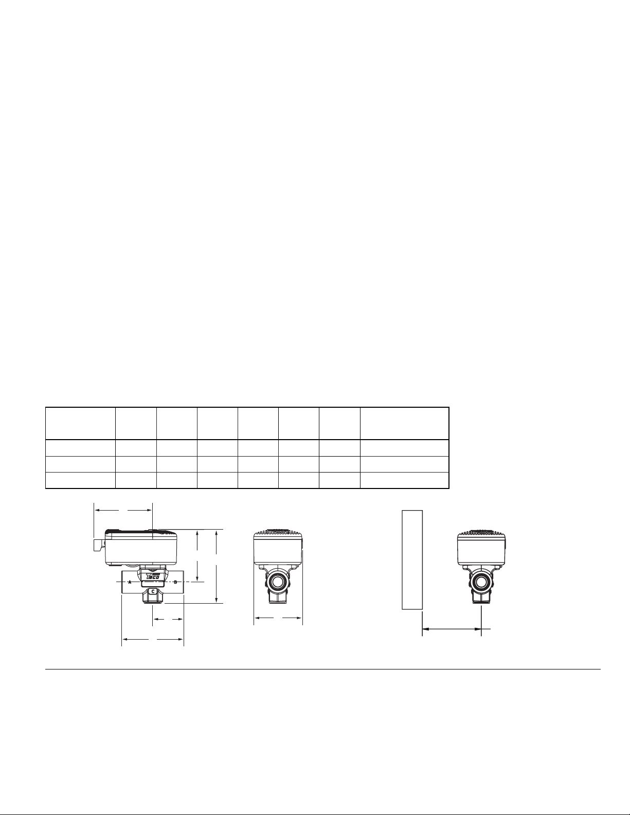
1. Valve body may be installed in any position, in
any orientation (see Figure A).
2. Before mounting body, refer to Figure B and
Dimensions Section for clearances.
3. Use of a solder with a melting point below 600°F
is recommended. Do not overheat! Make sure the
ball valve is in the FULL OPEN position during sol-
dering. Direct flame tip away from the center of
the valve. Cool valve quickly with a wet rag.
4. Solder build-up on the ball valve may prevent
proper opening and closing of the valve. Rotate
the manual operation button several times to
loosen any possible build-up.
5. Valve body can be submerged for leak testing
before the operator is attached.
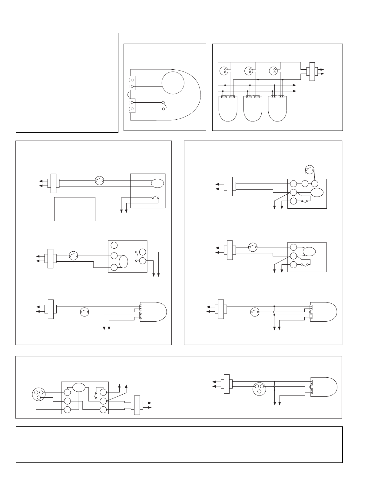
Operator Installation / Wiring:
1. Valve operator may be attached to the valve body
in either direction (see Figure A).
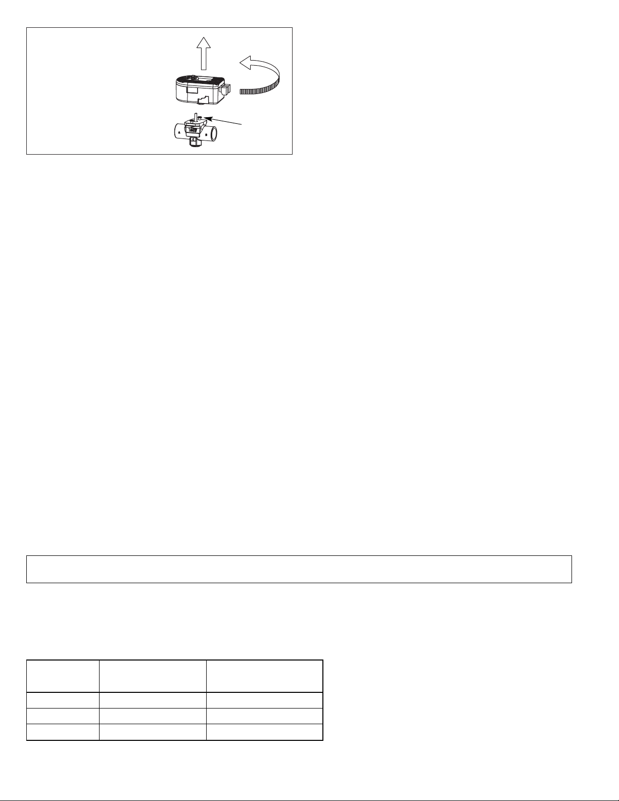
2. Operator removal: Remove valve operator prior to
soldering by rotating the operator counterclock-
wise approximately 30 degrees and lifting upward
approximately 3⁄4” (see Figure C).
Instruction Sheet
Electronic Ball Valve (EBV) Zone Valve
102-111
SUPERSEDES: 102-111, Dated August 1, 2003 EFFECTIVE: June 1, 2006
Plant ID# 001-1011
WARNING: Operator must be removed
from the valve body before soldering.
Ball valve must be in the full open posi-
tion before soldering. Valve shipped in
the closed position.
Figure A
Two Position Head Placement.
Universal Body Placement.
May be installed in any position, any orientation.
11⁄2" MIN.
OPERATOR
REMOVAL
CLEARANCE
W
A
L
L
Figure B

3. To re-assemble operator to valve body: Position
operator such that the “D” shaped valve stem
aligns properly with the “D” shaped operator drive
cavity (Note: The “D” shaped stem design allows
for correct insertion every time). Next, slide valve
stem into operator cavity and rotate until the oper-
ator slips over the valve’s locking posts (see Figure
C), once the operator is flush with valve body, turn
operator clockwise and lock into position.
4. Wire valve in accordance with system require-
ments, see wiring diagrams.
5. The plug-in quick connects can be disconnected
from the valve operator for ease of wiring. Insert the
corresponding wire into the quick connects (see
wiring diagrams) and tighten by turning the screw.
6. On a 24v system do not jumper power/motor (24
VAC) connection terminals, even temporarily.
This may cause damage to the thermostat’s heat
anticipator.
Mode of Operation, Start-Up:
1. Upon initial field installation the capacitor
requires a full charge, approximately 30 seconds
before the valve starts to turn. Do not disconnect
power to the actuator for at least 1 minute after
valve turns.
2. When the capacitor is charging the green LED
light will FLASH.
3. Once the capacitor is charged the green LED will
stop flashing but remain ON, at this point the
valve’s operator will rotate the ball valve until it
finds its “home” (the valves position when the
thermostat is calling). The “home” position, either
open or closed, is dependent on the style of valve
purchased (either normally opened or normally
closed).
NOTE: As the valve finds its “home” it may need
to travel almost 180°, depending on the initial ball
position. If it rotates past a 90° point it will close
the end switch (T T terminals) to verify connec-
tion. This may make it seem as if the device (i.e.
boiler) connected to the end switch terminals has
short cycled while the valve finds its “home”. This
will only occur once on initial start-up.
4. Once the valve finds its “home” the green LED will
remain ON as long as the thermostat is calling.
5. Once the thermostat is satisfied the green LED will
turn OFF and the Prostar Capacitor will discharge
some of its stored energy to rotate the valve 90°
into its normal position. For example: If the actu-
ator is an NC (normally closed) version, the oper-
ator would open the valve when the thermostat
calls. Once the thermostat is satisfied the operator
would then rotate the valve 90° to its normally
closed position.
Mode of Operation:
1. When the thermostat calls, the green LED will start
to FLASH for a short period of time as the Prostar
Capacitor completely refills its charge.
2. The green LED will then turn ON and the operator
will rotate the valve 90° into position.
3. The green LED will stay ON as long as the ther-
mostat is calling.
4. Once the thermostat is satisfied, the green LED
will turn OFF and the valve will rotate 90° to its
normal position.
Figure C: Operator Removal
Step 1
Rotate actuator counter
clockwise approximately 30
degrees
Step 2
Move actuator upward
3⁄4” to disengage
Locking
Post
VALVE SIZE Cv (Kv)/Ft.
of PIPE EQUIV.* CLOSE-OFF PSI (kPa)
1⁄2”4.9 (4.3) / 9.5 0-125 psi (0-862 kPa)
3⁄4”10.3 (8.9) / 8.4 0-125 psi (0-862 kPa)
1” 8.9 (7.7) / 47.4 0-125 psi (0-862 kPa)
Flow Coefficients and Maximum Close-Off Pressure:
*At 4' per second (max.
recommended residential
flow rate).
WARNING: Do not use zone valves on indirect water heaters without a tempering device.

Product Specifications:
Maximum Operating Pressure: 300 PSI (2,100 kPa)
Maximum Shutoff Pressure: 125 PSI (875 kPa)
Fluid Temperature Range: 20° to 240°F, (-7° to 115°C) @ 135°F (57°C) ambient
Installation must be in a non-condensing application.
Service: Closed systems
Hot Water, up to 50% Glycol
Ball Rotation Speed: Full Open to Full Close (90° turn), 4 seconds
Full Close to Full Open (90° turn), 6 seconds
Seat Leakage: Drop-Tight Close-Off
Electrical Rating: 24 VAC, 60 HZ, 0.54 Amps
Do not exceed number of valves per transformer rating. Example:
Do not use more than 12 zone valves per 40VA transformer.
Power Consumption, Charging: 12.84 Watts, 0.54 Amps Max
Power Consumption, Power On: 1.44 Watts, 0.06 Amps Max
Heat Anticipator Setting: 0.5 Amps
End Switch Rating: 3 Amps @ 24 VAC
Materials of Construction, Actuator:
Body: High Performance Engineered Polymer
Gears: High Performance Internally Lubricated Engineered Polymer
Materials of Construction, Valve:
Body: Forged Bronze
Stem: Brass
Press Ring: Brass
Ball: Brass (Chrome Plated)
Seat: Modified Teflon
O-rings: EPDM
VALVE SIZE AB E WEIGHT
(valve + actuator)
1⁄2”3” 23⁄8” 39⁄16” 29⁄16” 31⁄8”1.15 lbs
3⁄4”3” 23⁄8”33⁄4” 25⁄8” 31⁄8”1.20 lbs
1” 3” 23⁄8” 311⁄16” 25⁄8” 31⁄8”1.55 lbs
C
A
EC
G
F
B
Dimensions:
F G
19⁄16”
19⁄16”
19⁄16”
11⁄2" MIN.
OPERATOR
REMOVAL
CLEARANCE
W
A
L
L
“QUICK ORDER” PART NUMBERS
E050C2-1 > 1⁄2" 2-Way, Sweat, 24 VAC, Normally Closed, 4 Input Quick Connects
E075C2-1 > 3⁄4" 2-Way, Sweat, 24 VAC, Normally Closed, 4 Input Quick Connects
E100C2-1 > 1" 2-Way, Sweat, 24 VAC, Normally Closed, 4 Input Quick Connects
E050T2-1 > 1⁄2" 2-Way, Threaded, 24 VAC, Normally Closed, 4 Input Quick Connects
E075T2-1 > 3⁄4" 2-Way, Threaded, 24 VAC, Normally Closed, 4 Input Quick Connects
E100T2-1 > 1" 2-Way, Threaded, 24 VAC, Normally Closed, 4 Input Quick Connects

WARNING: Wiring connections
must be made in accordance
with all applicable electrical
codes.
CAUTION: To prevent electri-
cal shock, disconnect electric
power to system at main fuse
or circuit breaker box until
installation is complete.
When a service switch is
installed, more than one dis-
connect switch may be
required to deenergize this
device for servicing.
DOITONCE. DOITRIGHT.™
TACO, INC., 1160 Cranston Street, Cranston, RI 02920 Telephone: (401) 942-8000 FAX: (401) 942-2360.
TACO (Canada), Ltd., 6180 Ordan Drive, Mississauga, Ontario L5T 2B3. Telephone: 905/564-9422. FAX: 905/564-9436.
Visit our web site at: http://www.taco-hvac.com
Printed in USA
Copyright 2006
TACO, Inc.
Electronic Ball Valve (EBV) Zone Valve Wiring Diagrams
LED
Capacitor
(Motor)
End Switch
c
w/y
Simplified Internal
Schematic:
Thermostats Transformer
To “T” Terminals
on Boiler Control
Transformer Relay
T
T
Up to 12 Valves per
40va Transformer
L1 (Hot)
L2
24 v
End Switch
End Switch
End Switch
Rh/Rc
w/y
Rh/Rc
w/y
Rh/Rc
w/y
w/y
c
w/y
c
w/y
c
L1 (Hot)
L2
Thermostat
To “T” Terminals
Motor
See Chart
See Chart
Red
Red End Switch
Motor Wire Color
Honeywell = Yellow
Erie = Black
Sparco = Orange/Yellow
Honeywell, Erie and Sparco Wire Leads
Wiring a Taco EBV Zone Valve to Replace a
Honeywell, Erie or Sparco Valve:
Honeywell and Erie Terminal Block
L1 (Hot)
L2
Thermostat
To “T” Terminals
Motor
End Switch
TH
TR
TR
TH
ES
ES
L1 (Hot)
L2
Thermostat
To “T” Terminals on Boiler
Control Transformer Relay
Taco EBV Valve
c
End Switch
w/y
Wiring a Taco EBV Zone Valve to Replace a
Flair or Taco 3-Wire Valve:
L1 (Hot)
L2
Thermostat
To “T” Terminals on Boiler
Control Transformer Relay
Taco EBV Valve
Taco 570 Series
L1 (Hot)
L2
Thermostat
To “T” Terminals
Motor
End Switch
1
2
3
Flair
L1 (Hot)
L2
Thermostat
To “T” Terminals
Motor
End Switch
1
2
3
45
c
End Switch
w/y
Wiring a Taco EBV Zone Valve to Replace a White Rodgers Valve:
L1 (Hot)
L2
To “T” Terminals on Boiler
Control Transformer Relay
Taco EBV Valve
46
5
L1 (Hot)
L2
To “T” Terminals
Motor End Switch
6
4
White-Rodgers (1311 or 1321)
4
56
Thermostat
5
2
3
1
c
End Switch
Thermostat
w/y
Typical EBV Zone Valve Wiring:
Other Taco Control Unit manuals

Taco
Taco Zone Sentry User manual

Taco
Taco i Series User manual

Taco
Taco 5000-HX Series User manual

Taco
Taco ZVC404-EXP-4 User manual

Taco
Taco Comfort Solutions 5000-3 Series User manual

Taco
Taco FloodBreaker Manual

Taco
Taco HR Series Specifications

Taco
Taco 5123-WH-N User manual

Taco
Taco SR501 User manual

Taco
Taco 5000-2 User manual
Popular Control Unit manuals by other brands

Velleman
Velleman VMA410 user manual

BASF
BASF EXACTUS IFX-21 user guide

ELCOM
ELCOM TBM-300 Operating and assembly instructions

Festo
Festo HEL Series Installation and maintenance sheet

Vaillant
Vaillant myVAILLANT connect VR 940 installation instructions

Texas Instruments
Texas Instruments PCM1808EVM user guide