Taco 5123-WH-N User manual

In truction Sheet
5123-WH-N Lead Free (≤ .25% Pb) Mixing Valve
102-492
SUPERSEDES: July 2, 2015 EFFECTIVE: August 18, 2015
Plant I.D. 001-4206
WARNING: Water temperatures above 120°F can cause serious injury. Mixing valve temperature setting should
be done by a licensed professional per local code requirements. Use an accurate water thermometer and ver-
ify the final water temperature. The thermostatic strip provided must not be used for final water temperature
verification.
WARNING: The 5123-WH-N must not be installed on steam systems (water systems only).
WARNING: 5123-WH-N mixing valves are not designed to compensate for system pressure fluctuations
beyond the valves variation rating and should not be used where more sophisticated pressure compensating
temperature controls are required. These mixing valves are not intended to provide protection against
thermal shock.
CAUTION: Valve must not be subjected to heat during the installation, this may damage the valve’s internal
components.
CAUTION: Do not use excess thread sealant (in any form) as this may cause valve failure.
GENERAL:
The Taco 5123-WH-N is dual listed for both ASSE 1070 and ASSE 1017 applications.
• All installations should be carried out by a Licensed Professional. Failure to comply with all aspects of these instruc-
tions may result in unsafe performance. All installations must comply with relevant State and Local codes or authori-
ties.
• Ensure compatibility of valve installation, e.g. temperature of hot water, inlet pressure, flow rates, etc. -
refer to specification section. If the site conditions are outside of the specifications for the valve, the site
conditions must be corrected prior to installing the valve.
• Install in accordance with markings on valve body, i.e. hot water inlet - marked “H”, cold water inlet -
marked “C” and mixed outlet - marked “M”.
• Any inconsistency between these instructions and any specific instructions, bylaws or codes issued by
local authorities must be referred back to Taco, Inc. prior to any installation taking place.
• During startup ensure that the valve is set to the desired temperature (valve preset at 115-120°F (46-
49°C) with 150°F (66°C) hot water inlet temperature). If the valve temperature needs to be adjusted please
refer to the instructions below (MIXING VALVE TEMPERATURE ADJUSTMENT).
• A temperature strip is provided with each mixing valve and can be used as a reference to set the temper-
ature. The temperature strip must not be used for final temperature verification.
NOTE: If the water supply is of poor quality a filter or strainer should be fitted at the system inlet so
that both the water heater and the mixing valve are protected from dirt and debris.

MIXING VALVE TEMPERATURE ADJUSTMENT:
Prior to setting the valve it is necessary for the hot water source to be switched on and delivering hot water at the design
temperature.
INSTALLATION:
Before connecting the tee and mixing valve to the water heater, it is important to consider the alignment required to enable
connection of the tee to the mixing valve withthe flexible hose or piping and the positioning of the mixing valve to allow easy
access for adjustment. If a recirculation return line is also being installed the position of the recirculation port also needs to
be considered.
WRENCH
LOCKING
NUT
ALLEN
KEY
1. Apply sealing tape to the hot and cold
connections on the water heater.
Connect the hot inlet of the mixing
valve to the hot outlet of the water
heater, ensuring that the adjustment
mechanism is easily accessible and
that the recirculationport is positioned
for easy connection to the system
return line.
2. Connect the tee to the cold inlet
of the water heater, ensuring that
its mixing valve connection is
aligned to allow connection to the
mixing valve via the flexible hose
or hard pipe.
4. Connect system cold water inlet sup-
ply to the tee inlet and the system hot
water outlet supply to the mixing valve
outlet.
1. Using an accurate thermometer,
test the mixed water temperature
at the nearest outlet being sup-
plied by the valve. The test outlet
should not be a shower with its
own temperature limiting control
valve. This should be opened to
allow a minimum flow rate of 1.5
gpm (6 L/min). Allow the water to
run for at least one minute to
ensure the mixed water tempera-
ture has settled.
2. Holding the 3/16” Allen
key (supplied), loosen the
locking nut with a 7/16”
wrench.
3. Using the wrench to support the-
locking nut and prevent it from
rotating, turn the Allen key to
adjust the outlet temperature -
clockwise to decrease the
temperature, counterclockwise to
increase the temperature - until
the desired set point is reached.
4. Holding the Allen key, tight-
en the locking nut with the
wrench.
INSTALLATION IN RECIRCULATED SYSTEMS:
The 5123-WH-N includes a recirculation port
to allow return water from the system to be
connected directly back into the mixing
valve. To use this recirculation port, remove
the plug using an Allen key (3/8”).
1. 2.
3a. Insert the combination screen/gasket
into the nut side of the flexible hose
and connect the hose between the tee
and the mixing valve.
3a.
4.
1. 2.
3. 4.
3b. Connect the flexible hose/hard
pipe between the tee and the
mixing valve.
3b.

CHECKING/SERVICING THE MIXING VALVE:
• Note that this thermostatic mixing valve is a SAFE-
TYVALVE. It does not require routine maintenance
but should be checked annually to be sure it is func-
tioning properly. For installations with poor or
unknown water quality, or other adverse supply con-
ditions, it may be necessary to check the valve a
tmore frequent intervals.
• The temperature should be checked at the same out-
let as was used for commissioning in the first
instance. If the temperature is more than 5°F from
the commissioning temperature, refer to fault finding
guide below.
• There may be some variation in the temperature of
the water from the thermostatic mixing valve due to
seasonal temperature variations in the cold water
supply.
• The check valve can be easily accessed for cleaning
via the flexible hose connection.
•If the water supply is of poor or unknown quality
filters or strainer should be fitted at the inlet to
the system such that the cold inlet to both the
water heater and the mixing valve are protected
from dirt and debris.
FAULT / SYMPTOM CAUSE POSSIBLE SOLUTION
1. The desired mixed water temperature
cannot be obtained or valve is difficult
to set.
• Inlet temperatures are not within speci-
fication limits.
• Hot and cold supplies are reversed.
• Strainers are blocked.
• Ensure inlet temperatures are within
the specified limits for the valve.
• Refit the valve with Hot/Cold supplies
fitted to the correct connections.
• Clean strainers.
2. Mix temperature unstable or changing
over time.
• Strainers are blocked.
• Fluctuating supply pressures.
• Clean strainers.
• Install pressure regulating valves on
both hot and cold supplies.
3. Either full hot or full cold water flow-
ing from outlet fixture.
• Valve is incorrectly set.
• Hot and cold supplies are reversed.
• Hot/Cold water has migrated to other
inlet.
• Refer also to point 1.
• Adjust mix temperature as required.
• Refit the valve with Hot/Cold supplies
fitted to the correct connections.
• Verify the check valve is not fouled.
Clean if necessary.
4. No flow from the valve outlet. • Hot or cold water supply failure.
• Strainers are blocked.
• Restore inlet supplies and check mix
temperature.
• Clean strainers.
5. Flow rate reduced or fluctuating. • Strainers are blocked.
• Fluctuating supply pressures.
• Clean strainers.
• Install pressure regulating valves.
6. Mixed water temperature does not
change when temperature adjuster is
altered.
• Hot and cold supplies are reversed. • Refit the valve with Hot/Cold supplies
fitted to the correct connections.
7. Hot water flows into the cold water
system or vice versa.
• Check valves fouled. • Clean check valves, ensuring debris is
removed.
8. Valve is noisy.
• Excessive water velocity.
• Valve sized incorrectly.
• Reduce water velocity (best achieved
by fitting a pressure regulating valve).
• Check valve specifications and ensure
the appropriate valve is used for
required flow.
TROUBLESHOOTING:
This troubleshooting table is intended as a helpful guide and is not all inclusive. There could be other causes and solutions.
NOTE: This diagram is a guideline only. Any installation of a
recirculated system should be undertaken by a qualified trades-
man, and in accordance with the relevant codes and State,
Provincial and Local Authority requirements. Performance of the
system will be dependent on the other components specified
within it.

SPECIFICATIONS:
Hot Water Inlet Temperature: 120-180°F (49-82°C) utlet Water Temperature Range: 85-130°F (29-54°C)
Cold Water Inlet Temperature: 39-80°F (4-27°C)
Maximum Design Pressure: 230 psi Minimum Temperature Differential
(between hot supply and outlet): 27°F (15°C)
Minimum Flow Rate: 1 GPM (3.8 L/min) Allowable Supply Pressure Variation: ±20%1
Maximum Flow Rate: 12 GPM (45.4 L/min) Accuracy of utlet Temperature: ±5°F2(2.8°C)
Notes:
1. Maximum allowable variation in either supply pressure in
order to control the outlet temperature to within ±5°F.
Warning: Pressure variations outside of this range may
cause changes in the outlet temperature.
2. As tested in accordance with ASSE 1070.
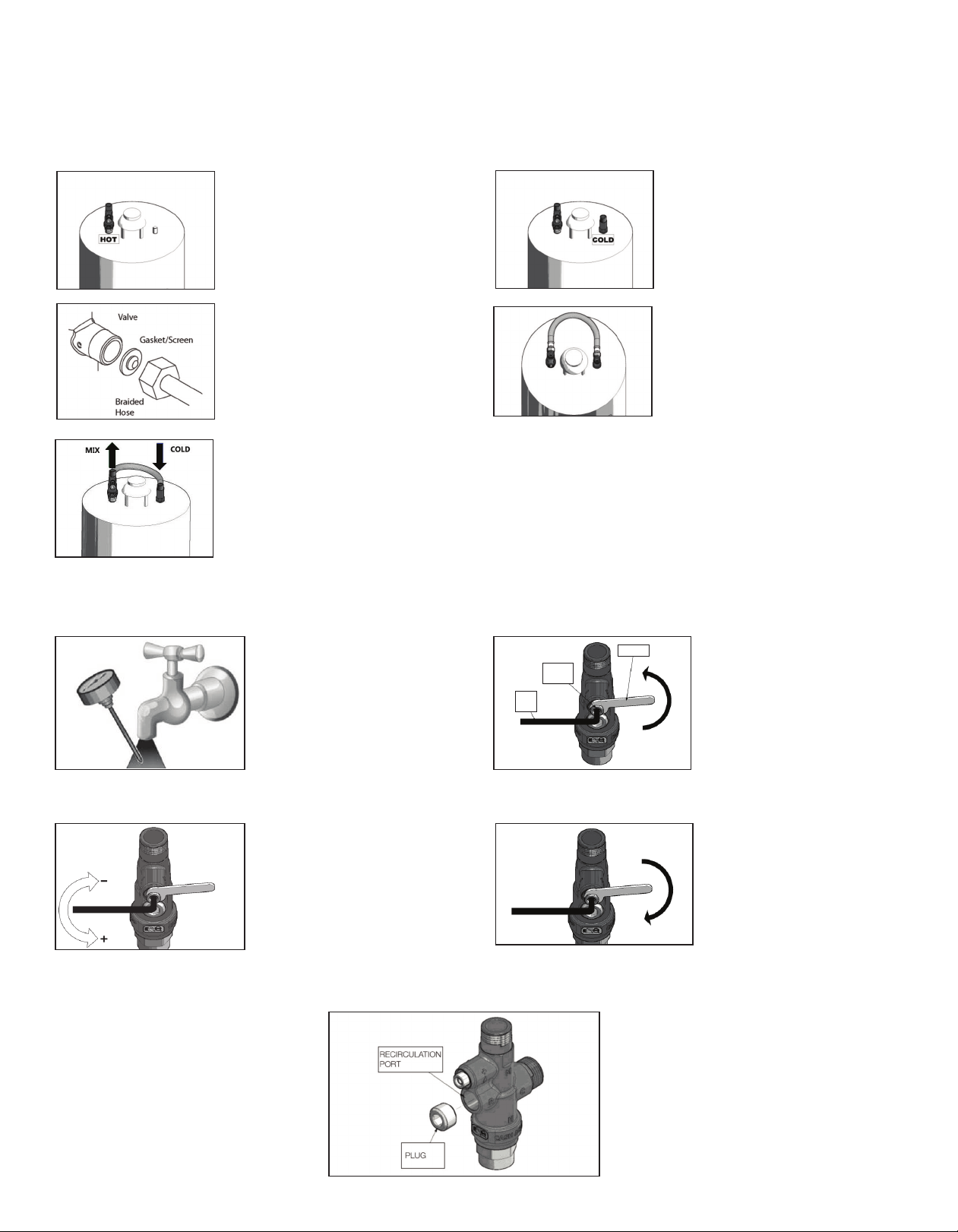
MAINTENANCE:
The Taco 5123-WH-N Mixing Valve is a SAFETY VALVE. It does
not require routine maintenance but should be checked annually
to be sure it is functioning properly. For installations with poor
water quality it may be necessary to inspect the mixing valve
more frequently. Replacement element assemblies are avail-
able.
Taco, Inc. will repair or replace without charge
(at the company’s option) any product or part
which is proven defective under normal use with-
in one (1) year from the date of start-up or one
(1) year and six (6) months from date of ship-
ment (whichever occurs first).
In order to obtain service under this warranty, it
is the responsibility of the purchaser to promptly
notify the local Taco stocking distributor or Taco
in writing and promptly deliver the subject prod-
uct or part, delivery prepaid, to the stocking dis-
tributor. For assistance on warranty returns, the
purchaser may either contact the local Taco
stocking distributor or Taco. If the subject prod-
uct or part contains no defect as covered in this
warranty, the purchaser will be billed for parts
and labor charges in effect at time of factory
examination and repair.
Any Taco product or part not installed or operat-
ed in conformity with Taco instructions or which
has been subject to misuse, misapplication, the
addition of petroleum-based fluids or certain
chemical additives to the systems, or other
abuse, will not be covered by this warranty.
If in doubt as to whether a particular substance
is suitable for use with a Taco product or part, or
for any application restrictions, consult the
applicable Taco instruction sheets or contact
Taco at (401-942-8000).
Taco reserves the right to provide replacement
products and parts which are substantially similar
in design and functionally equivalent to the defec-
tive product or part. Taco reserves the right to
make changes in details of design, construction,
or arrangement of materials of its products with-
out notification.
TACO OFFERS THIS WARRANTY IN LIEU OF
ALL OTHER EXPRESS WARRANTIES. ANY
WARRANTY IMPLIED BY LAW INCLUDING
WARRANTIES OF MERCHANTABILITY OR
FITNESS IS IN EFFECT ONLY FOR THE DURA-
TION OF THE EXPRESS WARRANTY SET
FORTH IN THE FIRST PARAGRAPH ABOVE.
THE ABOVE WARRANTIES ARE IN LIEU OF
ALL OTHER WARRANTIES, EXPRESS OR
STATUTORY, OR ANY OTHER WARRANTY
OBLIGATION ON THE PART OF TACO.
TACO WILL NOT BE LIABLE FOR ANY SPE-
CIAL, INCIDENTAL, INDIRECT OR CONSE-
QUENTIAL DAMAGES RESULTING FROM THE
USE OF ITS PRODUCTS OR ANY INCIDENTAL
COSTS OF REMOVING OR REPLACING
DEFECTIVE PRODUCTS.
This warranty gives the purchaser specific rights,
and the purchaser may have other rights which
vary from state to state. Some states do not
allow limitations on how long an implied warranty
lasts or on the exclusion of incidental or conse-
quential damages, so these limitations or exclu-
sions may not apply to you.
LIMITED WARRANTY STATEMENT
FLOW CURVE:
Other Taco Control Unit manuals

Taco
Taco SR501 User manual

Taco
Taco HR Series Specifications

Taco
Taco Zone Sentry Series User manual

Taco
Taco ZVC404-EXP-4 User manual

Taco
Taco FloodBreaker Manual

Taco
Taco Zone Sentry User manual

Taco
Taco 102-111 User manual

Taco
Taco i Series User manual

Taco
Taco 5000-HX Series User manual

Taco
Taco 5000-2 User manual
Popular Control Unit manuals by other brands

Wilo
Wilo Stratos PLR Installation and operating instructions

Gemu
Gemu 707 Installation, operating and maintenance instructions

Crane
Crane CRYOFLO T-Globe Installation, operation and maintenance manual

RWC
RWC Reliance MultiSafe Leak Detector Control... Operation and maintenance guide

Burkert
Burkert 2030 operating instructions

Wöhner
Wöhner CRITO CrossBoard Mounting instructions