Tadano GR-900XLL-4 User manual

GENERAL DIMENSIONS
Form NO. GR-900-4-00102/US-02
Turning radius (29.5–25 Tires)
4 wheel steer
2 wheel steer
Overall length
Overall width
Overall height
approx. 49' 9-7/8"
approx. 10' 10-1/2"
approx. 12' 5-13/16"
Feet
6.8
10.9
22' 4"
35' 9-3/32"
Meters Feet Meters
15.185
3.315
3.805
Note: Dimension is with boom angle at -1.5 degree.
( ) Reference dimensions in mm.
15'9" (4,790) SMART CW2
8'3-15/16" (2,538)
15.8°
Min.: 42.0'–Max.: 167.3' (12,800–51,000)
12'5-13/16" (3,805)
13'9" (4,190) SMART CW1
10'10-1/2" (3,315) 11'7-3/4" (3,550)
13.7°
7'2-5/8" (2,200)
1'6-1/8"
(460)
49'9-7/8" (15,185)
28'11-11/16' (8,830) 12'11-1/2" (3,950)
28'1-13/16" (8,580)
7'10-5/8"
(2,405)
12'4-7/8" (3,780)
6'1-7/8"
(1,875)
23'11-3/8" (7,300)
21'11-3/4" (6,700)
18'1/2" (5,500)
8'10-1/4" (2,700)
1'6-5/8" (475)
GR-900XLL-4
90 Ton (81.7 Metric Ton) Capacity
HYDRAULIC ROUGH TERRAIN CRANE
Specications are subject to change without notice.
DIMENSIONS
-
1
-

CRANE SPECIFICATIONS
BOOM
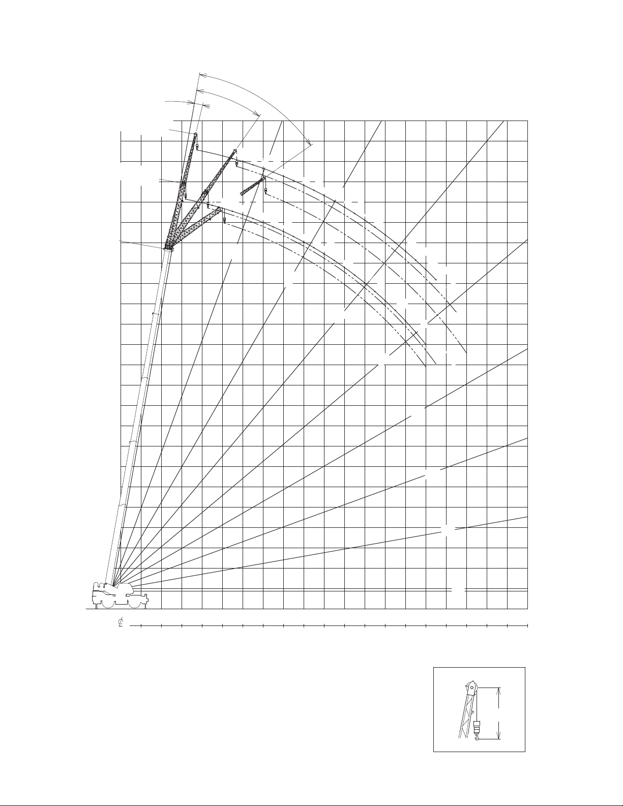
5 section full power synchronized telescoping boom, 42.0'–167.3'
(12.8 m–51.0 m), of round box construction with 7 sheaves,
17-5/16" (0.44 m) root diameter, at boom head.
The synchronization system consists of 2 telescope cylinders, an
extension cable and retraction cable. Hydraulic cylinder tted with
holding valve. 2 easily removable wire rope guards, rope dead
end provided on both sides of boom head. Boom telescope
sections are supported by wear pads both vertically and
horizontally. Extension speed 125.3’ in 170 seconds.
BOOM ELEVATION - By a double acting hydraulic cylinder
with holding valve. Elevation -1.5º-80.5º, combination controls for
hand or foot operation. Boom angle indicator.
Automatic speed reduction and slow stop function.
Boom raising speed 20º to 60º in 46 seconds.
JIB - 2 stage bi-fold lattice type, 3.5º, 25º or 45º offset (tilt type).
Single sheave, 15-5/8" (0.396 m) root diameter, at the head of
both jib sections. Stored alongside base boom section. Jib length
is 33.2' (10.1 m) or 58.1' (17.7 m). Assistant cylinders for mounting
and stowing, controlled at right side of superstructure. Self
stowing jib mounting pins.
AUXILIARY LIFTING SHEAVE (SINGLE TOP)
Single sheave, 15-5/8" (0.396 m) root diameter. Mounted to main
boom head for single line work (stowable).
ANTI-TWO BLOCK - Pendant type over-winding cut out
device with audio-visual (FAILURE lamp/BUZZER) warning
system.
SLEWING
Hydraulic axial piston motor through planetary slewing
speed reducer. Continuous 360º full circle slewing on ball bearing
turn table at 1.5 min
-1
{rpm}. Equipped with manually
locked/released slewing brake. A 360º positive slewing lock for
pick and carry and travel modes, manually engaged in cab.
Twin slewing system: Free slewing or lock slewing controlled by
selector switch on front console.
WINCH
MAIN WINCH - Variable speed type with grooved drum driven
by hydraulic axial piston motor through speed reducer.
Power load lowering and raising. Equipped with automatic
brake (neutral brake) and counterbalance valve. Controlled
independently of auxiliary winch. Equipped with cable follower
and drum rotation indicator.
DRUM - Grooved 14-1/4" (0.362 m) root diameter x 26-13/16"
(0.681 m) wide. Wire rope: 935' of
3/4"
diameter rope (285 m of 19
mm). Drum capacity: 1135' (346 m) 7 layers. Maximum single line
pull:1st layer 20,000 lbs (9,090 kg). Maximum permissible line pull
wire strength: 14,600 lbs (6,600 kg).
AUXILIARY WINCH - Variable speed type with grooved drum
driven by hydraulic axial piston motor through speed reducer.
Power load lowering and raising. Equipped with
automatic brake (neutral brake) and counterbalance valve.
Controlled independently of main winch. Equipped with cable
follower and drum rotation indicator.
DRUM - Grooved 14-1/4" (0.362 m) root diameter x 26-13/16"
(0.681 m) wide. Wire rope: 482'
of
3/4" diameter rope (147 m of 19
mm). Drum capacity: 1135' (346 m) 7 layers. Maximum single line
pull: 1st layer 20,000 lbs (9,090 kg). Maximum permissible line pull
wire strength: 14,600 lbs (6,600 kg).
WIRE ROPE
- Non-rotating 3/4" (19 mm) P・S (19) + 39 x P・7
Breaking Strength 72,800 lbs (33,000 kg)
HOOK BLOCKS
100 ton (90.7 metric ton)-8 sheaves with swivel hook and safety
latch, for 3/4" (19 mm) wire rope.
7.3 ton (6.6 metric ton) - Weighted hook with swivel and
safety latch, for 3/4" (19 mm) wire rope.
COUNTERWEIGHT
Self-removable counterweight ............... 24,700 lbs (11,200 kg)
HYDRAULIC SYSTEM
PUMPS - 2 variable piston pumps for crane functions.
Tandem gear pump for steering slewing and other hydraulic
systems. Powered by carrier engine. Pump disconnect for crane is
engaged/disengaged by rotary switch from operator's cab.
CONTROL VALVES - Multiple valves actuated by pilot
pressure with integral pressure relief valves.
RESERVOIR - 210 gallon (795 lit.) capacity. External sight
level gauge.
FILTRATION - BETA10=10 return lter, full ow with bypass
protection, located inside of hydraulic reservoir. Accessible for
easy replacement.
OIL COOLER - Air cooled fan type.
CAB AND CONTROLS
Both crane and drive operations can be performed from one
cab mounted on rotating superstructure.
20
º
tilt, Left side, 1 man type, steel construction with sliding door
access and safety glass windows opening at side. Door
window is powered control. Windshield glass window and roof
glass window are shatter-resistant. Tilt-telescoping steering
wheel. Adjustable control lever stands for slewing, boom
elevating, boom telescoping, auxiliary winch and main winch.
Control lever stands can change neutral positions and tilt for easy
access to cab. 3 way adjustable operator's seat with high back,
headrest and armrest. Engine throttle knob. Foot operated
controls: boom elevating boom telescoping, service brake and
engine throttle. Hot water cab heater and air conditioning.
Dash-mounted Instrument panel, Multi Function Display, Starter
switch (engine start/stop), 12 V power outlet, USB port, drive
selector switch, parking brake switch, steering mode select
switch, power window switch, pump engaged/disengaged switch,
slewing brake switch, telescoping/auxiliary winch select switch,
outrigger controls, free slewing/lock slewing selector switch, air
conditioning control switch.
Instruments panel - Torque converter oil temperature, engine
water temperature, air pressure, fuel, speedometer, tachometer,
hour meter and odometer/tripmeter.
Multi Function Display - DEF level gauge, Fuel consumption
monitor.
-
2
-
Form No. GR-900-4-00102/US-02

Tadano electronic LOAD MOMENT INDICATOR system
(AML-E2) including:
• Control lever lockout function with audible and visual
pre-warning
• Number of parts of line
• Boom position indicator
• Outrigger state indicator
• Slewing angle
• Boom angle / boom length / jib offset angle / jib length /
load radius / rated lifting capacities / actual loads read out
• Potential lifting height
• Ratio of actual load moment to rated load moment
indication
• Automatic Speed reduction and slow stop function on
boom elevation and slewing
• Working condition register switch
• Load radius / boom angle / tip height / slewing range preset
function
• External warning lamp
• Tare function
• Main Hydraulic oil pressure
• Fuel consumption monitor
• Main winch / auxiliary winch select
• Drum rotation indicator (audible and visible type) main and
auxiliary winch
• On rubber indicator
TADANO AML-E2 monitors outrigger extended length and
automatically programs the corresponding "RATED LIFTING
CAPACITIES" table.
Operator's right hand console includes transmission gear
selector, slewing lock lever and sight level bubble.
Upper console includes,
roof washer and wiper switch,
emergency outrigger set up key switch,
jib equipped / removed select switch,
high speed winch (main / aux) switch, Cab tilt switch,
Pump disconnect enable switch and boom emergency
telescoping switch (2nd and 3rd-top).
NOTE: Each crane motion speed is based on unladen conditions.
CARRIER SPECIFICATIONS
TYPE - Rear engine, left hand steering, driving axle 2-way
selected type by manual switch, 4 x 2 front drive, 4 x 4 front and
rear drive.
FRAME - High tensile steel, all welded mono-box construction.
TRANSMISSION - Electronically controlled full automatic
transmission. Torque converter driving full powershift with
driving axle selector. 6 forward and 2 reverse speeds, constant
mesh.
3 speeds - high range - 2 wheel drive; 4 wheel drive
3 speeds - low range - 4 wheel drive
TRAVEL SPEED - 22 mph (36 km/h)
GRADEABILITY (tanθ) - 84% (at stall), 57%*
* Machine should be operated within the limit of engine
crankcase design (30°: Cummins B6.7)
AXLE - Front: Full floating type, steering and driving axle with
planetary reduction. Rear: Full floating type, steering and driving
axle with planetary reduction and non-spin rear differential.
STEERING - Hydraulic power steering controlled by steering
wheel. Four steering modes available: 2 wheel front, 2 wheel
rear, 4 wheel coordinated and 4 wheel crab.
SUSPENSION - Front: Rigid mounted to frame. Rear: Pivot
mounted with hydraulic lockout device.
BRAKE SYSTEMS - Service: Air over hydraulic disc brakes on
all 4 wheels. Parking / Emergency: Spring applied-air released
brake acting on input shaft of front axle. Auxiliary: Electro-
pneumatic operated exhaust brake.
TIRES - 29.5-25 36PR (OR) Air pressure: 68 psi (470 kPa)
29.5-25 40PR (OR) Air pressure: 67 psi (465 kPa)
OUTRIGGERS- Four hydraulic, beam and jack outriggers.
Vertical jack cylinders equipped with integral holding valve. Each
outrigger beam and jack is controlled independently from cab.
Beams extend to 23' 11-3/8" (7.3 m) center-line and retract to
within 10' 10-1/2" (3.315 m) overall width with floats. Outrigger
jack floats are attached thus eliminating the need of manually
attaching and detaching them. Controls and sight bubble located
in superstructure cab. Four outrigger extension lengths are
provided with corresponding "RATED LIFTING CAPACITIES" for
crane duty in confined areas.
Min. Extension 8' 10-1/4" (2.7 m) center to center
Mid. Extension 18' 1/2" (5.5 m) center to center
Mid. Extension 21' 11-3/4" (6.7 m) center to center
Max. Extension 23' 11-3/8" (7.3 m) center to center
Float size (Diameter) 1' 11- 5/8" (0.6 m)
ENGINE
ModelCummins B6.7
Type Direct injection diesel
No. of cylinders 6
Combustion 4 cycle, turbo charged and after cooled
BoreXStroke, in. (mm) 4.212 X 4.882 (107 X 124)
Displacement, cu. in (liters) 409 (6.7)
Air inlet heater 24 volt preheat
Air cleaner Dry type, replaceable element
Oil filter Full flow with replaceable element
Fuel filter Full flow with replaceable element
Fuel tank, gal. (liters) 79.2 (300), right side of carrier
Cooling Liquid pressurized, recirculating by-pass
Radiator
Fin and tube core, thermostat controlled
Fan, in. (mm) Suction type, 9-blade, 28 (711) dia.
Starting 24 volt
Charging 24 volt system, negative ground
Battery 2-120 amp. Hour
Compressor, air, CFM (l /min)17.0 CFM (481) at 2,400 rpm
Output, Max. HP (kW) Gross 280 (209) at 2,200 rpm
Torque, Max. ft-lb (Nm) 850 (1,152) at 1,500 rpm
Capacity, gal. (liters)
Cooling water 2.7 (10)
Lubrication 4.0 (15)
Fuel 79.2 (300)
DEF/AdBlue 15.0 (57)
-
3
-
Form No. GR-900-4-00102/US-02

STANDARD EQUIPMENT
- 5 section full power partially synchronized boom
42.0'–167.3' (12.8 m–51.0 m)
- 33.2' or 58.1' (10.1 m or 17.7 m) bi-fold lattice jib (tilt type)
with 3.5º, 25º or 45º pinned offsets and self storing pins.
- Quick reeving type bi-fold jib
- Anti-Two block device (overwind cutout)
- Winch drum camera with light
- LED work lights
-
Variable speed main winch with grooved drum, cable follower, drum
rotation indicator (audible,visible and thumper type) and 935' of 3/4" cable.
-
Variable speed auxiliary winch with grooved drum, cable follower, drum
rotation indicator (audible, visible and thumper type) and 482' of 3/4" cable.
- Auxiliary lifting sheave (single top) stowable
- 2-speed winch
- 100 ton (90.7 metric ton) hook block - 8 sheave with swivel hook
and safety latch for 3/4" (19 mm) wire rope
- 7.3 ton (6.6 metric ton) hook with swivel
- Tadano twin slewing system and 360º positive slewing lock
- Positive control
- Hydraulic oil cooler
-
3 way adjustable cloth seat with armrests, high back and seat belt
- Tilt-telescoping steering wheel
- Tinted safety glass and sun visor
- Front windshield wiper and washer
- Roof window wiper and washer
- Power window (cab door)
- 12V power outlet
- Ashtray
- Cab oor mat
- Pump disconnect in operator's cab
- Air conditioner (hot water heater and cooler)
- Full instrumentation package
- Self centering nger control levers with pilot control
- Control pedals for boom elevating and boom telescoping
- Low oil pressure / high water temp. warning device (visual)
- Air cleaner dust indicator
- Cup holder
- Battery disconnect
- USB port
- 20º tilt cab
- Wind speed indicator
- Emergency steering system
- Tadano electronic load moment indicator system (AML-E2)
- Boom angle indicator
- Outrigger extension length detector
- Electronic crane monitoring system
- Rear view camera
- Right front view camera
- Fenders
- Air dryer
- Complete highway light package
- Towing hooks-Front and rear
- Hook block tie down (front bumper)
- Weighted hook storage compartment
- Halogen head lamp
- Independently controlled outriggers
- Four outrigger extension positions
- Self-storing outrigger pads
-
Electronic controlled automatic transmission driven by torque converter
- 4 X 4 X 4 drive / steer
- Non-spin rear differential
- Automatic rear axle oscillation lockout system
- 29.5-25 36 PR tires
- 29.5-25 40 PR tires
- Disc brakes
- Water separator with lter (high ltration)
- Back-up alarm
- 24 volt electric system
- Tool storage compartment
- Tire ination kit
- Cummins B6.7 turbo charged
after cooled engine (280 HP) with exhaust brake
- Engine over-run alarm
- Lifting eyes
- Telematics (machine data logging and monitoring system)
with HELLO-NET via internet (availability depends on countries)
- Fuel consumption monitor
- Eco mode system
- Self-removable counterweight
- Radiator cover
- Clearance sonar (Rear side)
- Automatic pump disconnect
- Over unwinding prevention
HOISTING PERFORMANCE
LINE SPEEDS AND PULLS DRUM WIRE ROPE CAPACITIES
- Maximum permissible line pull wire strength
14,600 lbs (6,600 kg).
1Line speeds based only on hook block, not loaded.
2Developed by machinery with each layer of wire rope, but not based
on rope strength or other limitation in machinery or equipment.
3Seventh layer of wire rope are not recommended
for hoisting operations.
-
4
-
DRUM DIMENSIONS
Inch mm
Root diameter
Length Flange
diameter
14-1/4"
26-13/16"
25-7/8"
362
681
657
Feet Meters Feet Meters
1 128.0 39.0 128.0 39.0
2 139.4 42.5 267.4 81.5
3 150.9 46.0 418.3 127.5
4 162.1 49.4 580.4 176.9
5 173.9 53.0 754.3 229.9
6 185.4 56.5 939.6 286.4
7 196.9 60.0 1,136.5 346.4
Total wire rope mRope per layer m
3/4" (19 mm) wire rope
Main and auxiliary drum grooved lagging
Wire
rope
layer
Layer
Low High Low High
F.P.M
m/min
Lbs. kgf Lbs. kgf
1st 278 84 118 20,000 9,090 14,400 6,520
2nd 302 92 128 18,100 8,230 13,000 5,900
3rd 327 99 139 16,600 7,520 11,900 5,390
4th 352 107 149 15,300 6,920 10,900 4,960
5th 377 115 160 14,100 6,410 10,100 4,600
6th 402 122 170 13,200 5,970 9,400 4,280
7th3427 130 181 12,300 5,590 8,800 4,010
Main or auxiliary hoist - 14'-1/4" (0.362 m) drum
Line speeds1 Line pulls Available2
F.P.M
m/min
387
421
456
491
526
560
595
Form No. GR-900-4-00102/US-02

Approx.
8.1'
Approx.
7.7'
1.9'
158.8
180
61.7
78.5
102
180
133.1
99.6
99.6
23.9
29.4
36.9
47.6
60.9
77.9
99.6
99.6
99.6
74.8
18.2
21
24.5
29
33.8
35.9
46.3
53.4
62.3
74.2
74.8
74.8
12.9
14.6
29.7
16.5
18.9
21.7
25.3
30.6
34.6
39.3
39.9
39.9
39.9
39.9
9.5
10.6
11.8
13.3
15
17
18.8
20.3
22
24.7
27.6
31.2
33.8
33.8
33.8
33.8
7.1
7.9
8.7
9.7
10.8
12.1
13.6
14.7
15.7
16.9
18.5
20.5
22.8
25.5
28.8
30
30
30
30
5.4
5.9
6.5
7.2
8
8.9
9.5
10.1
10.7
11.4
12.7
14.3
15.7
17.4
19.2
21.4
24
28.3
28.3
28.3
27.1
2.9
3.3
3.8
4.3
4.9
5.5
6.2
7
7.8
8.8
9.9
11.2
12.4
13.2
14.1
15.1
16.5
18.3
20.4
22.9
25.4
26.4
26.4
1.6
2
2.4
2.9
3.4
4
4.6
5.3
6.1
6.9
7.9
9
9.9
10.8
11.8
13
14.3
15.8
17.6
19
20.1
20.7
20.7
20°
30°
40°
50°
60°
70°
80°
10°
0°
NOTE: Boom geometry shown is for unloaded condition and
machine standing level on rm supporting surface.
Boom deection and subsequent radius and boom angle change
must be accounted for when applying load to hook.
When boom length is same as telescoping mode 1 and 2, it show large load.
Axis of Rotation
BOOM SINGLE TOP
190'
170'
42.0'
(12.8 m)
151.7'
(46.2 m)
167.3'
(51.0 m)
136.0'
(41.5 m)
104.7'
(31.9 m)
73.3'
(22.4 m)
57.7'
(17.6 m)
89.0'
(27.1 m)
20.3'
(36.7 m)
150'
170'
120'110'100'90' 140'80'70'60'50'40'
30'
20'10' 130'
140'
130'
120'
180'
110'
100'
90'
80'
70'
60'
50'
40'
30'
20'
10'
150'
160'
160'
Unit: klbs
-
5
-
Load Radius from Axis of Rotation in Feet
Lifting Height in Feet
SMART CW1
360° ROTATION
GR-900XLL-4 WORKING RANGE CHART
Form No. GR-900-4-00102/US-02

Approx.
8.1'
Approx.
7.7'
1.9'
1.3
1.6
0°
10°
80°
70°
60°
50°
40°
30°
20°
20.7
20.7
20.1
19
17.6
15.8
14.3
13
11.8
10.8
9.9
9
8.3
7.5
6.6
5.8
5
4.4
3.8
3.3
2.8
2.3
1.9
26.4
26.4
25.4
22.9
20.4
18.3
16.5
15.1
14.1
13.2
12.4
11.7
10.5
9.3
8.4
7.5
6.6
5.9
5.3
4.7
4.1
3.7
3.3
27.1
28.3
28.3
28.3
24
21.4
19.2
17.4
15.7
14.3
13.1
11.7
10.7
10.1
9.5
9
8.5
7.7
6.9
6.3
5.8
30
30
30
30
28.8
25.5
22.8
20.5
18.5
16.9
15.7
14.7
13.7
12.7
11.4
10.2
9.2
8.3
7.6
33.8
33.8
33.8
33.8
31.2
27.6
24.7
22.3
20.3
18.8
17.6
15.7
13.9
12.4
11.1
10
39.9
39.9
39.9
39.9
39.3
34.6
30.7
26.3
22.7
19.7
17.3
29.7
15.3
13.6
74.8
74.8
74.2
62.3
53.4
46.5
37.4
33.8
30.1
25.6
21.9
19
74.8
99.6
99.6
99.6
79.5
62.5
49.4
38.4
30.7
25.1
99.6
99.6
135.1
180
103.9
80.1
63.3
180
161
Axis of Rotation
BOOM SINGLE TOP
NOTE: Boom geometry shown is for unloaded condition and
machine standing level on rm supporting surface.
Boom deection and subsequent radius and boom angle change
must be accounted for when applying load to hook.
When boom length is same as telescoping mode 1 and 2, it show large load.
160'
160'
150'
10'
20'
30'
40'
50'
60'
70'
80'
90'
100'
110'
180'
120'
130'
140'
130'10' 20' 30' 40' 50' 60' 70' 80' 140'90' 100' 110' 120'
170'
150'
120.3'
(36.7 m)
89.0'
(27.1 m)
57.7'
(17.6 m)
73.3'
(22.4 m)
104.7'
(31.9 m)
136.0'
(41.5 m)
167.3'
(51.0 m)
151.7'
(46.2 m)
42.0'
(12.8 m)
Unit: klbs
170'
190'
6
- -
Load Radius from Axis of Rotation in Feet
Lifting Height in Feet
SMART CW2
360° ROTATION
GR-900XLL-4 WORKING RANGE CHART
Form No. GR-900-4-00102/US-02

Approx.
8.1'
Approx.
7.7'
1.9'
0°
10°
80°
70°
60°
50°
40°
30°
20°
20.7
20.7
20.1
19
17.6
15.8
14.3
13
11.8
10.8
9.9
9
8.3
7.6
7
6.4
5.9
5.4
5
4.6
4.1
3.6
3.1
26.4
26.4
25.4
22.9
20.4
18.3
16.5
15.1
14.1
13.2
12.4
11.7
11
10.3
9.7
9.1
8.3
7.5
6.8
6.1
5.5
5
4.5
27.1
28.3
28.3
28.3
24
21.4
19.2
17.4
15.7
14.3
13.1
12
11
10.1
9.5
9
8.6
8.2
7.8
7.5
7.2
30
30
30
30
28.8
25.5
22.8
20.5
18.5
16.9
15.7
14.7
13.7
12.9
12.2
11.5
11
10.1
9.3
33.8
33.8
33.8
33.8
31.2
27.6
24.7
22.3
20.3
18.8
17.6
16.4
15.5
14.6
13.4
12.1
39.9
39.9
39.9
39.9
39.3
34.6
30.7
29.6
26.2
23.3
20.5
29.7
18.2
16.2
74.8
74.8
74.2
62.3
53.4
46.5
40.3
33.8
33.2
29
25.6
22.6
74.8
99.6
99.6
99.6
79.5
62.5
49.9
41
34.3
25.9
99.6
99.6
135.1
180
103.9
80.1
63.3
180
161
2.7
2.4
Axis of Rotation
BOOM SINGLE TOP
NOTE: Boom geometry shown is for unloaded condition and
machine standing level on rm supporting surface.
Boom deection and subsequent radius and boom angle change
must be accounted for when applying load to hook.
When boom length is same as telescoping mode 1 and 2, it show large load.
160'
160'
150'
10'
20'
30'
40'
50'
60'
70'
80'
90'
100'
110'
180'
120'
130'
140'
130'10' 20' 30' 40' 50' 60' 70' 80' 140'90' 100' 110' 120'
170'
150'
120.3'
(36.7 m)
89.0'
(27.1 m)
57.7'
(17.6 m)
73.3'
(22.4 m)
104.7'
(31.9 m)
136.0'
(41.5 m)
167.3'
(51.0 m)
51.7'
(46.2 m)
42.0'
(12.8 m)
Unit: klbs
170'
190'
7
- -
Load Radius from Axis of Rotation in Feet
Lifting Height in Feet
SMART CW2
SMART CHART
GR-900XLL-4 WORKING RANGE CHART
Form No. GR-900-4-00102/US-02

Approx.
7.7'
1.5
1.9
2.2
2.7
3.1
3.6
4.2
4.8
5.4
6.2
6.6
6.7
6.7
6.7
6.7
6.7
6.7
6.7
6.7
6.7
6.7
1.5
1.9
2.3
2.8
3.3
3.9
4.5
5.1
5.8
6.6
7.5
8.5
9.2
9.8
10.4
10.4
10.4
10.4
10.4
10.4
10.4
10.4
3.5°
25°
45°
30°
40°
50°
60°
80°
70°
20°
10°
0°
NOTE: Jib geometry shown are for unloaded condition and
machine standing level on rm supporting surface.
Boom deection and subsequent radius and boom angle change
must be accounted for when applying load to hook.
Axis of Rotation
JIB
167.3' (51.0 m)
+ 58.1' (17.7 m)
167.3' (51.0 m)
+ 33.2' (10.1 m)
200'190'180'
200'
210'
220'
230'
240'
167.3'
(51.0 m)
Unit: klbs
190'
170'
140'
130'
120'
180'
110'
100'
90'
80'
70'
60'
50'
40'
30'
20'
10'
150'
160'
170'150'120'110'100'90' 140'80'70'60'50'40'
30'
20'10' 130' 160'
-
8
-
Load Radius from Axis of Rotation in Feet
Lifting Height in Feet
SMART CW1
360° ROTATION
GR-900XLL-4 WORKING RANGE CHART
Form No. GR-900-4-00102/US-02

Approx.
7.7'
1.9
2.2
2.6
3.1
3.5
4.1
4.6
5.2
5.8
6.2
6.6
6.7
6.7
6.7
6.7
6.7
6.7
6.7
6.7
6.7
6.7
1.9
2.3
2.8
3.2
3.7
4.3
4.9
5.6
6.3
7.2
7.9
8.7
9.2
9.8
10.4
10.4
10.4
10.4
10.4
10.4
10.4
10.4
3.5°
25°
45°
30°
40°
50°
60°
80°
70°
20°
10°
0°
1.5
1.5
1.2
NOTE: Jib geometry shown are for unloaded condition and
machine standing level on rm supporting surface.
Boom deection and subsequent radius and boom angle change
must be accounted for when applying load to hook.
Axis of Rotation
JIB
167.3' (51.0 m)
+ 58.1' (17.7 m)
167.3' (51.0 m)
+ 33.2' (10.1 m)
200'190'180'
200'
210'
220'
230'
240'
Unit: klbs
190'
170'
140'
130'
120'
180'
110'
100'
90'
80'
70'
60'
50'
40'
30'
20'
10'
150'
160'
170'150'120'110'100'90' 140'80'70'60'50'40'
30'
20'10' 130' 160'
167.3'
(51.0 m)
-
9
-
Lifting Height in Feet
Load Radius from Axis of Rotation in Feet
SMART CW2
360° ROTATION
GR-900XLL-4 WORKING RANGE CHART
Form No. GR-900-4-00102/US-02

Approx.
7.7'
1.1
1.1
3
3.4
3.7
4.1
4.5
4.9
5.2
5.5
5.8
6.2
6.6
6.7
6.7
6.7
6.7
6.7
6.7
6.7
6.7
6.7
6.7
3.1
3.5
3.9
4.3
4.7
5.1
5.6
6.1
6.7
7.3
7.9
8.7
9.2
9.8
10.4
10.4
10.4
10.4
10.4
10.4
10.4
10.4
3.5°
25°
45°
30°
40°
50°
60°
80°
70°
20°
10°
0°
2.6
2.3
1.9
1.6
1.3
2.7
2.3
2
1.7
1.3
NOTE: Jib geometry shown are for unloaded condition and
machine standing level on rm supporting surface.
Boom deection and subsequent radius and boom angle change
must be accounted for when applying load to hook.
Axis of Rotation
JIB
167.3' (51.0 m)
+ 58.1' (17.7 m)
167.3' (51.0 m)
+ 33.2' (10.1 m)
200'190'180'
200'
210'
220'
230'
240'
167.3'
(51.0 m)
Unit: klbs
190'
170'
140'
130'
120'
180'
110'
100'
90'
80'
70'
60'
50'
40'
30'
20'
10'
150'
160'
170'150'120'110'100'90' 140'80'70'60'50'40'
30'
20'10' 130' 160'
-
10
-
Lifting Height in Feet
Load Radius from Axis of Rotation in Feet
SMART CW2
SMART CHART
GR-900XLL-4 WORKING RANGE CHART
Form No. GR-900-4-00102/US-02

180,000
GR-900XLL-4 RATED LIFTING CAPACITIES (IN POUNDS)
A: Boom length in feet
B: Load radius in feet
C: Loaded boom angle ( º)
D: Minimum boom angle ( º) for indicated length (no load)
-
11
-
SMART CW1
A
A
CB
42.0'
35.2
(12.8 m)
19,700
1, 2
B
57.7'
50.7
(17.6 m)
10,900
1
B
73.3'
66.1
(22.4 m)
4,600
1
B
73.3'
66.1
(22.4 m)
9,500
2
B
89.0'
81.7
(27.1 m)
3,200
1
B
89.0'
81.8
(27.1 m)
6,700
2
B
104.7'
97.2
(31.9 m)
1,800
1
B
104.7'
97.2
(31.9 m)
5,100
2
B
120.3'
112.1
(36.7 m)
4,400
2
B
136.0'
126.7
(41.5 m)
3,900
2
0°
B
42.0'
(12.8 m)
57.7'
(17.6 m)
167.3'
(51 m)
8
10
12
15
20
25
30
35
40
45
50
55
60
65
70
75
80
85
90
95
100
105
110
115
120
125
130
135
140
145
D
Telescoping mode
Telescoping mode
2nd Boom 0
1, 2 1 1
50 100 0
2
100
1
0
2
100 0
2
100 0
2
100
1
0
2
100
1
50
2
100
1, 2
3rd Boom 0 0 0 33 16 50 33
1 1
0° 12° 0° 15° 13°10°0°
67 50 83 67 100 83 100 100
4th Boom 0 0 0 33 16 50 33 67 50 83 67 100 83 100 100
Top Boom 0 0 0 33 16 50 33 67 50 83 67 100 83 100 100
360° ROTATION
COUNTERWEIGHT 24,700lbs (11.2 t)
ON OUTRIGGERS FULLY EXTENDED 23' 11-3/8" (7.3 m) SPREAD
SMART CW1
360° ROTATION
COUNTERWEIGHT 24,700lbs (11.2 t)
ON OUTRIGGERS FULLY EXTENDED 23' 11-3/8" (7.3 m) SPREAD
73.3'
(22.4 m)
89.0'
(27.1 m)
104.7'
(31.9 m)
120.3'
(36.7 m)
136.0'
(41.5 m)
151.7'
(46.2 m)
NOTE: The lifting capacity data stored in the LOAD MOMENT INDICATOR (AML-E2) is based on the standard number of parts of line listed in the chart.
Standard number of parts of line for each boom length should be according to the following table.
42.0'
(12.8 m)
1, 2
16
42.0' to 73.3'
(12.8 m to 22.4 m)
73.3' to 167.3'
(22.4 m to 51 m)
1, 2
4
2
4
1
8
Single top
jib
1, 2
1
Boom length in feet
(meters)
Telescoping mode
Number of parts of line
99,600
180,000 99,600 74,800 33,800
158,800 99,600 74,800 33,800
133,100 99,600 74,800 33,800 39,900 29,700
102,000 99,600 74,200 33,800 39,900 29,700 33,800 27,700 30,000 27,600
78,500 77,900 62,300 33,800 39,900 29,700 33,800 27,700 30,000 27,600 28,300 27,500
61,700 60,900 53,400 33,800 39,900 29,700 33,800 27,700 30,000 27,600 28,300 26,100 26,400 24,100
47,600 46,300 33,800 39,300 29,700 33,800 27,700 30,000 27,400 28,300 23,900 26,400 23,600 20,700
36,900 35,900 33,800 34,600 29,700 31,200 27,700 28,800 25,000 27,100 21,500 25,400 22,000 20,700
29,400 28,500 33,800 30,600 29,700 27,600 26,300 25,500 23,000 24,000 19,500 22,900 20,500 20,100
23,900 23,000 29,000 25,000 29,700 24,700 23,900 22,800 21,200 21,400 17,800 20,400 19,100 19,000
18,800 24,500 20,800 25,300 21,800 22,000 20,500 19,800 19,200 16,300 18,300 17,600 17,600
15,400 21,000 17,400 21,700 18,400 20,300 18,500 18,200 17,400 15,000 16,500 16,200 15,800
12,800 18,200 14,600 18,900 15,700 18,800 16,400 16,900 15,700 14,000 14,900 15,100 14,300
12,300 16,500 13,400 17,000 14,100 15,700 14,300 13,000 13,600 14,100 13,000
10,400 14,600 11,400 15,000 12,200 14,700 12,700 12,100 12,400 13,200 11,800
8,800 12,900 9,800 13,300 10,500 13,600 11,000 11,400 11,300 12,400 10,800
8,400 11,800 9,100 12,100 9,600 10,700 10,000 11,200 9,900
7,200 10,600 7,900 10,800 8,400 10,100 8,800 9,900 9,000
6,100 9,500 6,800 9,700 7,300 9,500 7,600 8,800 7,900
5,800 8,700 6,300 8,900 6,700 7,800 6,900
5,000 7,900 5,500 8,000 5,800 7,000 6,100
4,300 7,100 4,700 7,200 5,000 6,200 5,300
4,000 6,500 4,300 5,500 4,600
3,400 5,900 3,700 4,900 4,000
2,900 5,400 3,200 4,300 3,400
2,700 3,800 2,900
2,200 3,300 2,400
1,800 2,900 2,000
26°
1,600
Form No. GR-900-4-00102/US-02

180,000 99,600
180,000 99,600 74,800 33,800
161,000 99,600 74,800 33,800
135,100 99,600 74,800 33,800 39,900 29,700
103,900 99,600 74,200 33,800 39,900 29,700 33,800 27,700 30,000 27,600
80,100 79,500 62,300 33,800 39,900 29,700 33,800 27,700 30,000 27,600 28,300 27,500
63,300 62,500 53,400 33,800 39,900 29,700 33,800 27,700 30,000 27,600 28,300 26,100 26,400 24,100
49,400 46,500 33,800 39,300 29,700 33,800 27,700 30,000 27,400 28,300 23,900 26,400 23,600 20,700
38,400 37,400 33,800 34,600 29,700 31,200 27,700 28,800 25,000 27,100 21,500 25,400 22,000 20,700
30,700 29,800 33,800 30,700 29,700 27,600 26,300 25,500 23,000 24,000 19,500 22,900 20,500 20,100
25,100 24,100 30,100 26,200 29,700 24,700 23,900 22,800 21,200 21,400 17,800 20,400 19,100 19,000
19,800 25,600 21,800 26,300 22,300 22,000 20,500 19,800 19,200 16,300 18,300 17,600 17,600
16,400 21,900 18,300 22,700 19,300 20,300 18,500 18,200 17,400 15,000 16,500 16,200 15,800
13,600 19,000 15,400 19,700 16,500 18,800 16,800 16,900 15,700 14,000 14,900 15,100 14,300
13,100 17,300 14,100 17,600 14,900 15,700 14,300 13,000 13,600 14,100 13,000
11,100 15,300 12,100 15,700 12,900 14,700 13,100 12,100 12,400 13,200 11,800
9,400 13,600 10,400 13,900 11,200 13,700 11,700 11,400 11,300 12,400 10,800
9,000 12,400 9,700 12,700 10,200 10,700 10,400 11,700 9,900
7,700 11,100 8,400 11,400 9,000 10,100 9,300 10,500 9,000
6,600 10,000 7,300 10,200 7,800 9,500 8,200 9,300 8,300
6,300 9,200 6,800 9,000 7,200 8,400 7,500
5,500 8,300 5,900 8,500 6,300 7,500 6,600
4,700 7,600 5,100 7,700 5,500 6,600 5,800
4,400 6,900 4,800 5,900 5,000
3,800 6,300 4,100 5,300 4,400
3,300 5,800 3,500 4,700 3,800
3,000 4,100 3,300
2,600 3,700 2,800
2,200 3,300 2,300
1,900
1,600
1,300
GR-900XLL-4 RATED LIFTING CAPACITIES (IN POUNDS)
A: Boom length in feet
B: Load radius in feet
C: Loaded boom angle ( º)
D: Minimum boom angle ( º) for indicated length (no load)
-
12
-
SMART CW2
A
B
42.0'
(12.8 m)
57.7'
(17.6 m)
167.3'
(51 m)
8
10
12
15
20
25
30
35
40
45
50
55
60
65
70
75
80
85
90
95
100
105
110
115
120
125
130
135
140
145
150
155
Telescoping mode
2nd Boom 0
1, 2 1 1
50 100 0
2
100
1
0
2
100 0
2
100 0
2
100
1
0
2
100
1
50
2
100
1, 2
3rd Boom 0 0 0 33 16 50 33
1 1
D
67 50 83 67 100 83 100 100
4th Boom 0 0 0 33 16 50 33 67 50 83 67 100 83 100 100
Top Boom 0 0 0 33 16 50 33 67 50 83 67 100 83 100 100
360° ROTATION
COUNTERWEIGHT 24,700lbs (11.2 t)
ON OUTRIGGERS FULLY EXTENDED 23' 11-3/8" (7.3 m) SPREAD
SMART CW2
360° ROTATION
COUNTERWEIGHT 24,700lbs (11.2 t)
ON OUTRIGGERS FULLY EXTENDED 23' 11-3/8" (7.3 m) SPREAD
73.3'
(22.4 m)
89.0'
(27.1 m)
104.7'
(31.9 m)
120.3'
(36.7 m)
136.0'
(41.5 m)
151.7'
(46.2 m)
NOTE: The lifting capacity data stored in the LOAD MOMENT INDICATOR (AML-E2) is based on the standard number of parts of line listed in the chart.
Standard number of parts of line for each boom length should be according to the following table.
0° 12° 0° 15° 13°10°0°
A
CB
42.0'
35.2
(12.8 m)
19,700
1, 2
B
57.7'
50.7
(17.6 m)
10,900
1
B
73.3'
66.1
(22.4 m)
4,600
1
B
73.3'
66.1
(22.4 m)
9,500
2
B
89.0'
81.7
(27.1 m)
3,200
1
B
89.0'
81.8
(27.1 m)
6,700
2
B
104.7'
97.2
(31.9 m)
1,800
1
B
104.7'
97.2
(31.9 m)
5,200
2
B
120.3'
112.1
(36.7 m)
4,500
2
B
136.0'
126.7
(41.5 m)
4,100
2
0°
Telescoping mode
42.0'
(12.8 m)
1, 2
16
42.0' to 73.3'
(12.8 m to 22.4 m)
73.3' to 167.3'
(22.4 m to 51 m)
1, 2
4
2
4
1
8
Single top
jib
1, 2
1
Boom length in feet
(meters)
Telescoping mode
Number of parts of line
18°
Form No. GR-900-4-00102/US-02

180,000
GR-900XLL-4 RATED LIFTING CAPACITIES (IN POUNDS)
-
13
-
99,600
180,000 99,600 74,800 33,800
161,000 99,600 74,800 33,800
135,100 99,600 74,800 33,800 39,900 29,700
103,900 99,600 74,200 33,800 39,900 29,700 33,800 27,700 30,000 27,600
80,100 79,500 62,300 33,800 39,900 29,700 33,800 27,700 30,000 27,600 28,300 27,500
63,300 62,500 53,400 33,800 39,900 29,700 33,800 27,700 30,000 27,600 28,300 26,100 26,400 24,100
49,900 46,500 33,800 39,300 29,700 33,800 27,700 30,000 27,400 28,300 23,900 26,400 23,600 20,700
41,000 40,300 33,800 34,600 29,700 31,200 27,700 28,800 25,000 27,100 21,500 25,400 22,000 20,700
34,300 33,600 33,800 30,700 29,700 27,600 26,300 25,500 23,000 24,000 19,500 22,900 20,500 20,100
29,200 28,400 33,200 27,500 29,700 24,700 23,900 22,800 21,200 21,400 17,800 20,400 19,100 19,000
24,200 29,000 24,800 29,600 22,300 22,000 20,500 19,800 19,200 16,300 18,300 17,600 17,600
20,200 25,600 22,200 26,200 20,200 20,300 18,500 18,200 17,400 15,000 16,500 16,200 15,800
17,100 22,600 18,900 23,300 18,300 18,800 16,800 16,900 15,700 14,000 14,900 15,100 14,300
16,100 20,500 16,800 17,600 15,400 15,700 14,300 13,000 13,600 14,100 13,000
13,900 18,200 15,000 16,400 14,100 14,700 13,100 12,100 12,400 13,200 11,800
11,900 16,200 13,000 15,500 12,900 13,700 12,000 11,400 11,300 12,400 10,800
11,300 14,600 11,900 12,900 11,000 10,700 10,400 11,700 9,900
9,900 13,400 10,600 12,200 10,100 10,100 9,500 11,000 9,000
8,600 12,100 9,300 11,500 9,300 9,500 8,700 10,300 8,300
8,200 11,000 8,600 9,000 8,000 9,700 7,600
7,200 10,100 7,700 8,600 7,400 9,100 7,000
6,300 9,300 6,800 8,200 6,800 8,300 6,400
6,000 7,800 6,300 7,500 5,900
5,300 7,500 5,600 6,800 5,400
4,700 7,200 5,000 6,100 5,000
4,400 5,500 4,600
3,800 5,000 4,100
3,400 4,500 3,600
3,100
2,700
2,400
SMART CW2
SMART CHART
A
B
42.0'
(12.8 m)
57.7'
(17.6 m)
167.3'
(51 m)
8
10
12
15
20
25
30
35
40
45
50
55
60
65
70
75
80
85
90
95
100
105
110
115
120
125
130
135
140
145
150
155
Telescoping mode
2nd Boom 0 50 100 0 100 0 100 0 100 0 100 0 100 50 100
3rd Boom 0 0 0 33 16 50 33 67 50 83 67 100 83 100 100
4th Boom 0 0 0 33 16 50 33 67 50 83 67 100 83 100 100
Top Boom 0 0 0 33 16 50 33 67 50 83 67 100 83 100 100
COUNTERWEIGHT 24,700lbs (11.2 t)
ON OUTRIGGERS FULLY EXTENDED 23' 11-3/8" (7.3 m) SPREAD
SMART CW2
SMART CHART
COUNTERWEIGHT 24,700lbs (11.2 t)
ON OUTRIGGERS FULLY EXTENDED 23' 11-3/8" (7.3 m) SPREAD
73.3'
(22.4 m)
89.0'
(27.1 m)
104.7'
(31.9 m)
120.3'
(36.7 m)
136.0'
(41.5 m)
151.7'
(46.2 m)
1, 2 1 1 2 1 2 2 2 1 2 1 2 1, 21 1
D11°9° 0° 0° 13° 12°0°
A
CB
42.0'
35.2
(12.8 m)
19,700
1, 2
B
57.7'
50.7
(17.6 m)
10,900
1
B
73.3'
66.1
(22.4 m)
4,600
1
B
73.3'
66.1
(22.4 m)
9,500
2
B
89.0'
81.7
(27.1 m)
3,400
1
B
89.0'
81.7
(27.1 m)
7,000
2
B
104.7'
97.2
(31.9 m)
2,000
1
B
104.7'
97.2
(31.9 m)
5,400
2
B
120.3'
112.1
(36.7 m)
5,100
2
B
136.0'
126.5
(41.5 m)
5,200
2
0°
Telescoping mode
A: Boom length in feet
B: Load radius in feet
C: Loaded boom angle ( º)
D: Minimum boom angle ( º) for indicated length (no load)
NOTE: The lifting capacity data stored in the LOAD MOMENT INDICATOR (AML-E2) is based on the standard number of parts of line listed in the chart.
Standard number of parts of line for each boom length should be according to the following table.
16°
42.0'
(12.8 m)
1, 2
16
42.0' to 73.3'
(12.8 m to 22.4 m)
73.3' to 167.3'
(22.4 m to 51 m)
1, 2
4
2
4
1
8
Single top
jib
1, 2
1
Boom length in feet
(meters)
Telescoping mode
Number of parts of line
20º 20º
20º 20º
Form No. GR-900-4-00102/US-02

GR-900XLL-4 RATED LIFTING CAPACITIES (IN POUNDS)
B: Load radius in feet
3.5° Offset 25° Offset 45° Offset
45
50
55
60
65
70
75
80
85
90
95
100
105
110
115
120
125
130
135
140
145
150
155
160
165
170
Telescoping
mode
Telescoping
mode
167.3' (51 m) Boom + 33.2 ' (10.1 m) JIB
B
45
50
55
60
65
70
75
80
85
90
95
100
105
110
115
120
125
130
135
140
145
150
155
160
165
170
B3.5° Offset 25° Offset 45° Offset
167.3' (51 m) Boom + 58.1 ' (17.7 m) JIB
3.5° Offset 25° Offset 45° Offset
40
45
50
55
60
65
70
75
80
85
90
95
100
105
110
115
120
125
130
135
140
145
150
155
160
165
170
175
180
185
Telescoping
mode
151.7' (46.2 m) Boom + 33.2 ' (10.1 m) JIB
B3.5° Offset 25° Offset 45° Offset
40
45
50
55
60
65
70
75
80
85
90
95
100
105
110
115
120
125
130
135
140
145
150
155
160
165
170
175
180
185
Telescoping
mode
151.7' (46.2 m) Boom + 58.1 ' (17.7 m) JIB
B
3.5° Offset 25° Offset 45° Offset
30
35
40
45
50
55
60
65
70
75
80
85
90
95
100
105
110
115
120
125
130
135
140
145
150
155
160
165
170
Telescoping
mode
120.3' (36.7 m) Boom + 33.2 ' (10.1 m) JIB
B
14,600
3.5° Offset 25° Offset 45° Offset
30
35
40
45
50
55
60
65
70
75
80
85
90
95
100
105
110
115
120
125
130
135
140
145
150
155
160
165
170
Telescoping
mode
120.3' (36.7 m) Boom + 58.1 ' (17.7 m) JIB
B
9,900
12,500
7,600
10,400
6,700
COUNTERWEIGHT 24,700 lbs (11.2 t)
ON OUTRIGGERS FULLY EXTENDED 23' 11-3/8" (7.3 m) SPREAD
360° ROTATION
SMART CW1
COUNTERWEIGHT 24,700 lbs (11.2 t)
ON OUTRIGGERS FULLY EXTENDED 23' 11-3/8" (7.3 m) SPREAD
360° ROTATION
SMART CW1
COUNTERWEIGHT 24,700 lbs (11.2 t)
ON OUTRIGGERS FULLY EXTENDED 23' 11-3/8" (7.3 m) SPREAD
360° ROTATION
SMART CW1
1, 21, 2
1 1 12 2 2 1 1 12 2 2
1 1 12 2 2 1 1 12 2 2
1, 2 1, 21, 2 1, 2
-
14
-
8,700
9,900 8,700
9,900 8,700
7,200
9,900 8,700
7,600 7,200
9,900 8,700 7,200 7,000
7,600 7,200
6,700
9,600 8,700 7,000 6,800
7,600 7,200
6,700
9,100 8,700 6,700 6,500 5,300 5,300
7,600 7,200 6,500 6,500
6,700
8,700 8,400 6,500 6,300 5,200 5,100
7,600 7,200 6,300 6,300
6,700 6,200
8,300 8,000 6,300 6,200 5,000 5,000
7,600 7,200 6,200 6,100 5,000
6,700 6,100
8,000 7,700 6,100 6,000 4,900 4,800
7,600 7,200 6,000 5,900 4,900 4,900
6,700 5,900
7,700 7,400 5,800 5,800 4,700 4,700
7,600 7,200 5,900 5,800 4,800 4,800
6,700 5,800 4,800
7,400 7,100 5,600 5,500 4,600 4,600
7,300 7,000 5,700 5,600 4,700 4,700
6,700 5,600 4,700
7,100 6,900 5,400 5,300 4,500 4,500
7,100 6,500 5,600 5,500 4,600 4,500
6,700 5,500 4,600
6,800 6,600 5,200 5,200 4,400 4,400
6,900 6,100 5,400 5,400 4,500 4,500
6,600 5,400 4,500
6,600 6,400 5,100 5,000 4,300 4,300
6,400 5,800 5,300 5,300 4,400 4,400
6,200 5,300 4,400
6,000 6,200 4,900 4,900 4,300 4,200
5,700 5,400 5,200 5,100 4,300 4,300
5,400 5,200 4,300
5,300 6,000 4,800 4,700 4,200 4,100
5,000 5,100 5,000 4,800 4,200 4,200
4,800 5,000 4,200
4,700 5,800 4,600 4,600 4,100 4,100
4,400 4,800 4,900 4,600 4,100 4,100
4,200 4,900 4,200
4,100 5,600 4,500 4,500 4,100 4,000
3,900 4,600 4,700 4,300 4,100 4,100
3,600 4,600 4,100
3,600 5,300 4,300 4,300 4,000 4,000
3,400 4,300 4,300 4,100 4,000 4,000
3,100 4,200 4,000
3,100 5,000 3,700 4,300 4,000 4,000
2,900 3,800 3,800 3,900 4,000 3,800
2,700 3,700 4,000
2,700 4,500 3,200 4,200
2,500 3,400 3,300 3,700 3,800 3,700
2,200 3,200 3,800
2,300 4,100 2,800 4,100
2,100 3,000 2,800 3,500 3,300 3,500
1,900 2,700 3,200
1,900 3,700 2,300 4,000
1,700 2,600 2,400 3,200 2,800 3,300
1,500 2,300 2,800
1,600 3,400 1,900 3,600
1,300 2,200 2,000 2,800 2,300 3,100
1,900 2,300
1,300 3,100
1,900 1,600 2,500
1,500 1,900
900 2,800
1,600 1,300 2,100
1,500
1,400 1,800
1,100 1,500
1,200
14,600
14,600 14,600
14,600 14,600 14,400
11,500
14,600 14,600 13,800 13,600
12,500 11,500
14,600 14,600 13,200 13,000 10,400 10,400
12,500 11,500
10,400
14,600 14,600 12,700 12,500 10,200 10,100
12,500 11,500 12,500 11,500
10,400
14,600 14,400 12,200 12,000 9,900 9,800
12,500 11,500 12,500 11,500 10,000 10,000
10,400 10,400
14,600 13,400 11,800 11,600 9,700 9,600
12,500 11,500 12,100 11,100 9,800 9,700
10,400 10,400 9,800
14,600 12,600 11,400 11,200 9,500 9,400
12,500 11,500 11,700 10,300 9,600 9,500
10,400 10,400 9,600
13,900 12,400 11,000 10,800 9,300 9,200
12,500 10,900 11,400 9,700 9,400 9,200
10,400 10,200 9,400
12,400 11,700 10,700 10,500 9,200 9,100
11,700 10,300 11,000 9,100 9,200 8,600
10,400 9,500 9,000
10,900 11,000 10,400 10,200 9,000 8,900
10,700 9,800 10,700 8,500 9,100 8,200
9,800 9,000 8,500
9,600 10,300 10,100 9,900 8,900 8,800
9,800 8,600 10,100 8,000 8,900 7,700
9,200 8,500 8,100
8,500 9,800 9,300 9,700 8,800 8,700
8,700 8,000 9,300 7,600 8,800 7,300
8,500 8,000 7,700
7,500 9,300 8,200 9,200 8,600 8,600
7,700 7,600 8,600 7,100 8,700 6,900
7,500 7,600 7,300
6,600 8,800 7,200 8,700 7,600 8,500
6,800 7,100 7,600 6,800 8,000 6,600
6,700 7,200 6,900
5,800 7,900 6,300 8,300 6,600 8,300
6,000 6,700 6,700 6,400 7,200 6,200
5,800 6,700 6,600
5,000 7,200 5,500 7,600 5,800 7,800
5,200 6,200 6,000 6,100 6,300 6,000
5,100 5,900 6,300
4,400 6,500 4,800 6,900
4,600 5,600 5,200 5,800 5,600 5,700
4,500 5,200 5,600
3,700 5,900 4,100 6,200
4,000 5,000 4,600 5,400 4,900 5,400
3,900 4,500 4,900
3,200 5,400 3,500 5,600
3,400 4,400 3,900 4,900 4,200 5,000
3,300 3,900 4,300
2,700 4,900 2,900 5,000
2,900 3,900 3,400 4,300 3,600 4,500
2,800 3,400 3,700
2,200 4,400
2,400 3,400 2,900 3,800
2,400 2,800 3,100
1,800 4,000
2,000 3,000 2,400 3,300
1,900 2,400 2,600
1,600 2,600 2,000 2,900
1,500 1,900 2,100
1,300 2,200 1,500 2,400
1,500
900 1,900 1,100 2,100
1,500 1,700
1,300
1,000
Form No. GR-900-4-00102/US-02

GR-900XLL-4 RATED LIFTING CAPACITIES (IN POUNDS)
B: Load radius in feet
3.5° Offset 25° Offset 45° Offset
45
50
55
60
65
70
75
80
85
90
95
100
105
110
115
120
125
130
135
140
145
150
155
160
165
170
175
Telescoping
mode
Telescoping
mode
167.3' (51 m) Boom + 33.2 ' (10.1 m) JIB
B
45
50
55
60
65
70
75
80
85
90
95
100
105
110
115
120
125
130
135
140
145
150
155
160
165
170
175
B3.5° Offset 25° Offset 45° Offset
167.3' (51 m) Boom + 58.1 ' (17.7 m) JIB
3.5° Offset 25° Offset 45° Offset
40
45
50
55
60
65
70
75
80
85
90
95
100
105
110
115
120
125
130
135
140
145
150
155
160
165
170
175
180
185
Telescoping
mode
151.7' (46.2 m) Boom + 33.2 ' (10.1 m) JIB
B3.5° Offset 25° Offset 45° Offset
40
45
50
55
60
65
70
75
80
85
90
95
100
105
110
115
120
125
130
135
140
145
150
155
160
165
170
175
180
185
Telescoping
mode
151.7' (46.2 m) Boom + 58.1 ' (17.7 m) JIB
B
3.5° Offset 25° Offset 45° Offset
30
35
40
45
50
55
60
65
70
75
80
85
90
95
100
105
110
115
120
125
130
135
140
145
150
155
160
165
170
Telescoping
mode
120.3' (36.7 m) Boom + 33.2 ' (10.1 m) JIB
B
14,600
3.5° Offset 25° Offset 45° Offset
30
35
40
45
50
55
60
65
70
75
80
85
90
95
100
105
110
115
120
125
130
135
140
145
150
155
160
165
170
Telescoping
mode
120.3' (36.7 m) Boom + 58.1 ' (17.7 m) JIB
B
9,900 8,700
9,900 8,700
9,900 8,700
9,900 8,700
9,900 8,700 7,200 7,000
9,600 8,700 7,000 6,800
9,100 8,700 6,700 6,500 5,300 5,300
8,700 8,400 6,500 6,300 5,200 5,100
8,300 8,000 6,300 6,200 5,000 5,000
8,000 7,700 6,100 6,000 4,900 4,800
7,700 7,400 5,800 5,800 4,700 4,700
7,400 7,100 5,600 5,500 4,600 4,600
7,100 6,900 5,400 5,300 4,500 4,500
6,800 6,600 5,200 5,200 4,400 4,400
6,600 6,400 5,100 5,000 4,300 4,300
6,400 6,200 4,900 4,900 4,300 4,200
5,700 6,000 4,800 4,700 4,200 4,100
5,100 5,800 4,600 4,600 4,100 4,100
4,500 5,600 4,500 4,500 4,100 4,000
4,000 5,300 4,400 4,300 4,000 4,000
3,500 5,100 4,100 4,300 4,000 4,000
3,000 4,900 3,600 4,200
2,600 4,400 3,100 4,100
2,200 4,100 2,600 4,000
1,900 3,700 2,200 3,900
1,500 3,400
1,200 3,100
12,500
7,600 7,200
7,600 7,200
7,600 7,200
7,600 7,200
7,600 7,200 6,500 6,500
7,600 7,200 6,300 6,300
7,600 7,200 6,200 6,100 5,000
7,600 7,200 6,000 5,900 4,900 4,900
7,600 7,200 5,900 5,800 4,800 4,800
7,300 7,000 5,700 5,600 4,700 4,700
7,100 6,500 5,600 5,500 4,600 4,500
6,900 6,100 5,400 5,400 4,500 4,500
6,700 5,800 5,300 5,300 4,400 4,400
6,200 5,400 5,200 5,100 4,300 4,300
5,500 5,100 5,000 4,800 4,200 4,200
4,900 4,800 4,900 4,600 4,100 4,100
4,300 4,600 4,700 4,300 4,100 4,100
3,800 4,300 4,600 4,100 4,000 4,000
3,300 4,100 4,200 3,900 4,000 3,800
2,800 3,700 3,700 3,700 3,900 3,700
2,400 3,400 3,200 3,500 3,700 3,500
2,100 3,000 2,800 3,400 3,200 3,300
1,700 2,600 2,300 3,200 2,700 3,200
1,400 2,300 1,900 2,800
1,100 2,000 1,600 2,400
1,700 1,200 2,100
1,400 1,700
1,200 1,400
10,400
6,700
6,700
6,700
6,700
6,700 6,200
6,700 6,100
6,700 5,900
6,700 5,800 4,800
6,700 5,600 4,700
6,700 5,500 4,600
6,600 5,400 4,500
6,200 5,300 4,400
5,800 5,200 4,300
5,200 5,000 4,200
4,600 4,900 4,200
4,100 4,600 4,100
3,500 4,400 4,000
3,100 4,100 4,000
2,600 3,500 3,900
2,200 3,100 3,600
1,900 2,600 3,100
1,500 2,200 2,700
1,900 2,200
1,500 1,800
1,400
COUNTERWEIGHT 24,700 lbs (11.2 t)
ON OUTRIGGERS FULLY EXTENDED 23' 11-3/8" (7.3 m) SPREAD
360° ROTATION
SMART CW2
COUNTERWEIGHT 24,700 lbs (11.2 t)
ON OUTRIGGERS FULLY EXTENDED 23' 11-3/8" (7.3 m) SPREAD
360° ROTATION
SMART CW2
COUNTERWEIGHT 24,700 lbs (11.2 t)
ON OUTRIGGERS FULLY EXTENDED 23' 11-3/8" (7.3 m) SPREAD
360° ROTATION
SMART CW2
14,600
14,600 14,600
14,600 14,600 14,400
14,600 14,600 13,800 13,600
14,600 14,600 13,200 13,000 10,400 10,400
14,600 14,600 12,700 12,500 10,200 10,100
14,600 14,400 12,200 12,000 9,900 9,800
14,600 13,400 11,800 11,600 9,700 9,600
14,600 12,600 11,400 11,200 9,500 9,400
13,900 12,400 11,000 10,800 9,300 9,200
12,800 11,700 10,700 10,500 9,200 9,100
11,500 11,000 10,400 10,200 9,000 8,900
10,200 10,300 10,100 9,900 8,900 8,800
9,000 9,800 9,800 9,700 8,800 8,700
8,000 9,300 8,700 9,200 8,700 8,600
7,000 8,800 7,700 8,700 8,000 8,500
6,200 8,300 6,800 8,300 7,100 8,300
5,400 7,600 6,000 7,900 6,200 7,900
4,800 6,900 5,200 7,300
4,100 6,300 4,500 6,600
3,600 5,800 3,900 6,000
3,100 5,200 3,300 5,400
2,600 4,700
2,200 4,300
11,500
12,500 11,500
12,500 11,500
12,500 11,500 12,500 11,500
12,500 11,500 12,500 11,500 10,000 10,000
12,500 11,500 12,100 11,100 9,800 9,700
12,500 11,500 11,700 10,300 9,600 9,500
12,500 10,900 11,400 9,700 9,400 9,200
11,700 10,300 11,000 9,100 9,200 8,600
10,700 9,800 10,700 8,500 9,100 8,200
9,800 8,600 10,100 8,000 8,900 7,700
9,000 8,000 9,300 7,600 8,800 7,300
8,200 7,600 8,600 7,100 8,700 6,900
7,300 7,100 7,900 6,800 8,000 6,600
6,500 6,700 7,200 6,400 7,400 6,200
5,700 6,300 6,400 6,100 6,800 6,000
5,000 6,000 5,600 5,800 6,000 5,700
4,400 5,400 5,000 5,500 5,200 5,400
3,800 4,800 4,400 5,200 4,600 5,200
3,300 4,300 3,800 4,700 4,000 4,800
2,800 3,800 3,300 4,100
2,400 3,300 2,800 3,600
2,000 2,900 2,300 3,200
1,600 2,500 1,900 2,800
1,300 2,200 1,500 2,400
1,900 1,100 2,000
1,500
1,300
10,400
10,400
10,400 10,400
10,400 10,400 9,800
10,400 10,400 9,600
10,400 10,200 9,400
10,400 9,500 9,000
9,800 9,000 8,500
9,200 8,500 8,100
8,700 8,000 7,700
7,900 7,600 7,300
7,200 7,200 6,900
6,300 6,800 6,600
5,600 6,300 6,300
4,900 5,600 6,000
4,300 4,900 5,300
3,700 4,300 4,700
3,200 3,800 4,100
2,800 3,200 3,500
2,300 2,800 3,000
1,900 2,300 2,500
1, 2
1,500 1,900
1,200
1, 2
1 1 12 2 2 1 1 12 2 2
1 1 12 2 2 1 1 12 2 2
1,500
1,100
1, 2 1, 21, 2 1, 2
-
15
-
Form No. GR-900-4-00102/US-02

GR-900XLL-4 RATED LIFTING CAPACITIES (IN POUNDS)
B: Load radius in feet
3.5° Offset 25° Offset 45° Offset
45
50
55
60
65
70
75
80
85
90
95
100
105
110
115
120
125
130
135
140
145
150
155
160
165
170
175
180
185
190
Telescoping
mode
Telescoping
mode
COUNTERWEIGHT 24,700 lbs (11.2 t)
ON OUTRIGGERS FULLY EXTENDED 23' 11-3/8" (7.3 m) SPREAD
SMART CHART
SMART CW2
COUNTERWEIGHT 24,700 lbs (11.2 t)
ON OUTRIGGERS FULLY EXTENDED 23' 11-3/8" (7.3 m) SPREAD
SMART CHART
SMART CW2
COUNTERWEIGHT 24,700 lbs (11.2 t)
ON OUTRIGGERS FULLY EXTENDED 23' 11-3/8" (7.3 m) SPREAD
SMART CHART
SMART CW2
167.3' (51 m) Boom + 33.2 ' (10.1 m) JIB
B
45
50
55
60
65
70
75
80
85
90
95
100
105
110
115
120
125
130
135
140
145
150
155
160
165
170
175
180
185
B3.5° Offset 25° Offset 45° Offset
167.3' (51 m) Boom + 58.1 ' (17.7 m) JIB
3.5° Offset 25° Offset 45° Offset
40
45
50
55
60
65
70
75
80
85
90
95
100
105
110
115
120
125
130
135
140
145
150
155
160
165
170
175
180
185
Telescoping
mode
151.7' (46.2 m) Boom + 33.2 ' (10.1 m) JIB
B3.5° Offset 25° Offset 45° Offset
40
45
50
55
60
65
70
75
80
85
90
95
100
105
110
115
120
125
130
135
140
145
150
155
160
165
170
175
180
185
190 190
Telescoping
mode
151.7' (46.2 m) Boom + 58.1 ' (17.7 m) JIB
B
3.5° Offset 25° Offset 45° Offset
30
35
40
45
50
55
60
65
70
75
80
85
90
95
100
105
110
115
120
125
130
135
140
145
150
155
160
165
170
Telescoping
mode
120.3' (36.7 m) Boom + 33.2 ' (10.1 m) JIB
B
14,600
3.5° Offset 25° Offset 45° Offset
30
35
40
45
50
55
60
65
70
75
80
85
90
95
100
105
110
115
120
125
130
135
140
145
150
155
160
165
170
Telescoping
mode
120.3' (36.7 m) Boom + 58.1 ' (17.7 m) JIB
B
9,900
12,500
7,600
10,400
6,700
8,700
9,900 8,700
9,900 8,700
9,900 8,700
9,900 8,700 7,200 7,000
9,600 8,700 7,000 6,800
9,100 8,700 6,700 6,500 5,300 5,300
8,700 8,400 6,500 6,300 5,200 5,100
8,300 8,000 6,300 6,200 5,000 5,000
8,000 7,700 6,100 6,000 4,900 4,800
7,700 7,400 5,800 5,800 4,700 4,700
7,400 7,100 5,600 5,500 4,600 4,600
7,100 6,900 5,400 5,300 4,500 4,500
6,800 6,600 5,200 5,200 4,400 4,400
6,600 6,400 5,100 5,000 4,300 4,300
6,400 6,200 4,900 4,900 4,300 4,200
6,100 6,000 4,800 4,700 4,200 4,100
5,900 5,800 4,600 4,600 4,100 4,100
5,600 5,600 4,500 4,500 4,100 4,000
5,200 5,300 4,400 4,300 4,000 4,000
4,700 5,100 4,300 4,300 4,000 4,000
4,200 5,000 4,200 4,200
3,700 4,800 4,100 4,100
3,300 4,600 3,700 4,000
2,900 4,500 3,200 4,000
2,600 4,400
2,200 4,100
7,200
7,600 7,200
7,600 7,200
7,600 7,200
7,600 7,200 6,500 6,500
7,600 7,200 6,300 6,300
7,600 7,200 6,200 6,100 5,000
7,600 7,200 6,000 5,900 4,900 4,900
7,600 7,200 5,900 5,800 4,800 4,800
7,300 7,000 5,700 5,600 4,700 4,700
7,100 6,500 5,600 5,500 4,600 4,500
6,900 6,100 5,400 5,400 4,500 4,500
6,700 5,800 5,300 5,300 4,400 4,400
6,500 5,400 5,200 5,100 4,300 4,300
6,100 5,100 5,000 4,800 4,200 4,200
5,600 4,800 4,900 4,600 4,100 4,100
5,200 4,600 4,700 4,300 4,100 4,100
4,700 4,300 4,600 4,100 4,000 4,000
4,400 4,100 4,500 3,900 4,000 3,800
4,000 3,900 4,400 3,700 3,900 3,700
3,700 3,700 4,100 3,500 3,900 3,500
3,200 3,500 3,700 3,400 3,800 3,300
2,800 3,300 3,400 3,200 3,500 3,200
2,500 3,100 3,100 3,100
2,100 3,000 2,700 2,900
1,800 2,700 2,300 2,800
2,400 1,900 2,700
2,100 1,600 2,300
1,800 1,200 2,000
6,700
6,700
6,700
6,700 6,200
6,700 6,100
6,700 5,900
6,700 5,800 4,800
6,700 5,600 4,700
6,700 5,500 4,600
6,600 5,400 4,500
6,200 5,300 4,400
5,800 5,200 4,300
5,500 5,000 4,200
5,200 4,900 4,200
4,900 4,600 4,100
4,500 4,400 4,000
4,100 4,200 4,000
3,700 4,000 3,900
3,400 3,800 3,700
3,000 3,500 3,500
2,600 3,200 3,400
2,300 2,900 3,100
1,900 2,600 2,800
1,600 2,200 2,500
1,300 1,900
1,100
190
1,500
1,200
14,600
14,600 14,600
14,600 14,600 14,400
11,500
14,600 14,600 13,800 13,600
12,500 11,500
14,600 14,600 13,200 13,000 10,400 10,400
12,500 11,500
10,400
14,600 14,600 12,700 12,500 10,200 10,100
12,500 11,500 12,500 11,500
10,400
14,600 14,400 12,200 12,000 9,900 9,800
12,500 11,500 12,500 11,500 10,000 10,000
10,400 10,400
14,600 13,400 11,800 11,600 9,700 9,600
12,500 11,500 12,100 11,100 9,800 9,700
10,400 10,400 9,800
14,600 12,600 11,400 11,200 9,500 9,400
12,500 11,500 11,700 10,300 9,600 9,500
10,400 10,400 9,600
13,900 12,400 11,000 10,800 9,300 9,200
12,500 10,900 11,400 9,700 9,400 9,200
10,400 10,200 9,400
12,800 11,700 10,700 10,500 9,200 9,100
11,700 10,300 11,000 9,100 9,200 8,600
10,400 9,500 9,000
11,700 11,000 10,400 10,200 9,000 8,900
10,700 9,800 10,700 8,500 9,100 8,200
9,800 9,000 8,500
10,800 10,300 10,100 9,900 8,900 8,800
9,800 8,600 10,100 8,000 8,900 7,700
9,200 8,500 8,100
10,000 9,800 9,900 9,700 8,800 8,700
9,000 8,000 9,300 7,600 8,800 7,300
8,700 8,000 7,700
9,200 9,300 9,400 9,200 8,700 8,600
8,200 7,600 8,600 7,100 8,700 6,900
7,900 7,600 7,300
8,500 8,800 8,700 8,700 8,600 8,500
7,600 7,100 7,900 6,800 8,000 6,600
7,300 7,200 6,900
7,900 8,300 8,100 8,300 8,200 8,300
7,000 6,700 7,300 6,400 7,400 6,200
6,700 6,800 6,600
7,000 7,900 7,500 7,900 7,600 7,900
6,400 6,300 6,700 6,100 6,800 6,000
6,100 6,500 6,300
6,300 7,500 6,700 7,500
5,900 6,000 6,200 5,800 6,300 5,700
5,600 5,900 6,000
5,600 7,200 6,000 7,200
5,400 5,700 5,700 5,500 5,800 5,400
5,100 5,400 5,600
4,900 6,900 5,200 6,800
5,000 5,400 5,200 5,200 5,300 5,200
4,700 5,000 5,100
4,300 6,500 4,600 6,500
4,600 5,100 4,800 5,000 4,900 4,900
4,300 4,600 4,700
3,800 6,000
4,100 4,900 4,400 4,700
3,900 4,200 4,300
3,300 5,500
3,600 4,500 3,900 4,500
3,500 3,800 3,900
3,200 4,100 3,400 4,300
3,100 3,400 3,500
2,700 3,600 3,000 3,900
2,700 3,100
2,300 3,200 2,500 3,400
2,300 2,700
2,000 2,900 2,100 3,000
2,000 2,300
1,600 2,500
1,700 1,900
1,300 2,200
1,300 1,500
1,100 1,200
1, 21, 2
1 1 12 2 2 1 1 12 2 2
1 1 12 2 2 1 1 12 2 2
1, 2 1, 21, 2 1, 2
-
16
-
Form No. GR-900-4-00102/US-02

-
17
-
SMART COUNTERWEIGHT
You can increase the capacity by changing the mounting position of the counterweight.
•
SMART CW 1: Counterweight is mounted at the front.
•
SMART CW 2: Counterweight is mounted at the rear.
SMART CW 1 status
SMART CW 2 status
13’ 9” (4,190 mm)
15’ 9” (4,790 mm)
Form No. GR-900-4-00102/US-02

WARNING AND OPERATING INSTRUCTIONS
FOR LIFTING CAPACITIES
-
18
-
GENERAL
RATED LIFTING CAPACITIES apply only to the machine as
originally manufactured and normally equipped by TADANO LTD.
Modications to the machine or use of optional equipment other
than that specied can result in a reduction of capacity.
Hydraulic cranes can be hazardous if improperly operated or
maintained. Operation and maintenance of this machine must be
in compliance with information, in the Operation Manual
supplied with the crane.If this manual is missing, order a
replacement through the distributor.
The operator and other personnel associated with this machine
shall fully acquaint themselves with the latest American National
Standards Institute (ANSI) safety standards for cranes.
SET UP
Rated lifting capacities on the chart are the maximum allowable
crane capacities and are based on the machine standing level on
rm supporting surface under ideal job conditions. Depending on
the nature of the supporting surface,it may be necessary to have
structural supports under the outrigger oats or tires to spread
the loads to a larger bearing surface.
For outrigger operation, outriggers shall be properly extended
with tires free of supporting surface before operating crane.
OPERATION
Rated lifting capacities have been tested to and meet minimum
requirements of SAE J1063-Cantilevered Boom Crane Structures
Method of Test.
Rated lifting capacities do not exceed 85% of the tipping load on
outriggers fully extended as determined by SAE J765-Crane
Stability Test Code.
Rated lifting capacities for partially extended outriggers are
determined from the formula, Rated Lifting Capacities = (Tipping
Load - 0.1 × Tip Reaction)/ 1.25.
Rated lifting capacities are based on actual load radius increased
by boom deection.
The weight of handling device such as hook blocks, slings, etc.,
must be considered as part of the load and must be deducted
from the lifting capacities.
Rated lifting capacities are based on freely suspended loads and
make no allowance for such factors as the effect of wind,sudden
stopping of loads,supporting surface conditions, ination of tires,
operating speeds,side loads, etc. Side pull on boom or jib is
extremely dangerous.
Such action can damage the boom, jib or slewing mechanism,
and lead to overturning of the crane.
Rated lifting capacities do not account for wind on lifted load or
boom. We recommend against working under the condition that
the load is out of control due to a strong wind. During boom
lift,consider that the rated lifting capacity is reduced by 50%
when the wind speed is 20 mph (9 m/s) to 27 mph (12 m/s);
reduced by 70% when the wind speed is 27 mph (12 m/s) to 31
mph (14 m/s). If the wind speed is 31 mph (14 m/s) or over, stop
operation. During jib lift, stop operation if the wind speed is 20
mph (9 m/s) or over.
Rated lifting capacities at load radius shall not be exceeded.
Do not tip the crane to determine allowable loads.
Do not operate at boom lengths, radii,or boom angle, where no
capacities are shown. Crane may overturn without any load on
the hook.
When boom length is between values listed, refer to the rated
lifting capacities of the next longer and next shorter booms for
the same radius. The lesser of the two rated lifting capacities
shall be used.
When making lifts at a load radius not shown, use the next
longer radius to determine allowable capacity.
Load per line should not exceed 14,600 lbs. (6,600 kg) for main
winch and auxiliary winch.
Check the actual number of parts of line with LOAD MOMENT
INDICATOR (AML-E2) before operation. Maximum lifting capacity
is restricted by the number of parts of line of LOAD MOMENT
INDICATOR (AML-E2). Limited capacity is as determined from
the formula, Single line pull for main winch 14,600 lbs. (6,600 kg)
× number of parts of line.
1.
2.
3.
1.
2.
1.
2.
3.
4.
5.
6.
7.
8.
9.
10.
11.
12.
13.
14.
15.
16.
17.
18.
19.
20.
21.
22.
1.
2.
3.
4.
5.
The boom angle before loading should be greater to account for
deection. For rated lifting capacities,the loaded boom angle and
the load radius is for reference only.
The 42.0' (12.8 m) boom length capacities are based on boom
fully retracted. If not fully retracted [less than 57.7' (17.6 m) boom
length], use the rated lifting capacities for the 57.7' (17.6 m)
boom length.
Extension or retraction of the boom with loads may be attempted
within the limits of the RATED LIFTING CAPACITIES.
The ability to telescope loads is limited by hydraulic pressure,
boom angle, boom length,crane maintenance, etc.
For lifting capacity of single top, deduct the weight of the load
handling equipment from the rated lifting capacity of the boom.
For the lifting capacity of single top, the net capacity shall not
exceed 14,600 lbs. (6,600 kg) including the main boom hook
mass attached to the boom.
When the base jib or top jib or both jibs are removed, set the jib
state switch to the REMOVED position.
When erecting and stowing jib, be sure to retain it by hand or by
other means to prevent its free movement.
Use ”ANTI-TWOBLOCK" disable switch when erecting and
stowing jib and when stowing hook block. While the switch is
pushed,the hoist does not stop,even when overwind condition
occurs.
When lifting a load by using jib (aux. winch)and boom (main
winch) simultaneously,do the following:
・Enter the operation status as jib operation, not as boom
operation.
・Before starting operation,make sure that mass of load is within
rated lifting capacity for jib.
Before telescoping the boom,set the telescoping mode selector
switch to mode 1 or mode 2 fully retracted.
A change of the telescoping mode is not permissible when the
boom has been partially or fully extended.
Crane operation is prohibited without full counterweight 24,700
lbs. (11.2 ton) installed.Outriggers shall be extended 23' 11-3 / 8”
(7.3 m) spread when installing or removing removable counter-
weight.
DEFINITIONS
Load Radius: Horizontal distance from a projection of the axis of
rotation to supporting surface before loading to the center of the
vertical hoist line or tackle with load applied.
Loaded Boom Angle: The angle between the boom base section
and the horizontal, after lifting the rated lifting capacity at the
load radius.
Working Area: Area measured in a circular arc about the
centerline of rotation.
Freely Suspended Load: Load hanging free with no direct
external force applied except by the hoist line.
Side Load: Horizontal side force applied to the lifted load either
on the ground or in the air.
Form No. GR-900-4-00102/US-02

GR-900XLL-4 RATED LIFTING CAPACITIES (IN POUNDS)
-
19
-
A
B
42.0'
(12.8 m)
73.3'
Over front
(22.4 m)
89.0'
(27.1 m)
104.7'
(31.9 m)
12
15
20
25
30
35
40
45
50
55
60
65
70
75
80
85
90
95
D 0°
Telescoping mode
2nd Boom 0
1, 2
0
2
0
2
0
21, 2 22 2
0° 29° 43° 50°
3rd Boom 0 33 50 67
4th Boom 0 33 50 67
Top Boom 0 33 50 67
65,000
53,700
40,400 33,800 29,700
31,400 33,800 29,700 27,700
24,200 27,300 27,800 27,700
21,200 21,700 22,000
16,800 17,400 17,800
13,600 14,200 14,500
11,100 11,600 12,000
9,100 9,700 10,000
7,500 8,000 8,400
6,200 6,700 7,100
5,600 5,900
4,700 5,000
3,900 4,200
3,400
2,800
2,300
A
B
42.0'
(12.8 m)
73.3'
360° Rotation
(22.4 m)
89.0'
(27.1 m)
104.7'
(31.9 m)
12
15
20
25
30
35
40
45
50
55
60
65
70
75
80
85
90
95
D
Telescoping mode
2nd Boom 0 0 0 0
3rd Boom 0 33 50 67
4th Boom 0 33 50 67
Top Boom 0 33 50 67
43,000
32,600
19,400 22,900 22,900
12,500 15,700 16,400 16,800
8,100 11,200 11,800 12,200
8,100 8,700 9,100
5,800 6,400 6,800
4,100 4,700 5,100
2,800 3,400 3,700
1,700 2,300 2,600
50,600
41,400
30,400 33,300 29,700
23,200 26,100 26,700 27,000
17,900 20,900 21,500 21,900
17,000 17,600 17,900
13,900 14,500 14,900
11,400 12,000 12,400
9,400 10,000 10,400
7,700 8,300 8,700
6,300 6,900 7,300
5,100 5,700 6,100
4,700 5,000
3,800 4,100
3,000 3,300
2,600
2,000
1,500
A
B
42.0'
(12.8 m)
73.3'
Over front
(22.4 m)
89.0'
(27.1 m)
104.7'
(31.9 m)
12
15
20
25
30
35
40
45
50
55
60
65
70
75
80
85
90
95
D
Telescoping mode
2nd Boom 0 0 0 0
3rd Boom 0 33 50 67
4th Boom 0 33 50 67
Top Boom 0 33 50 67
1, 2 2
0°
2 2
COUNTERWEIGHT 24,700lbs (11.2 t)
ON RUBBER STATIONARY
SMART CW1
ON RUBBER CREEP
COUNTERWEIGHT 24,700lbs (11.2 t)
SMART CW1
A: Boom length in feet
B: Load radius in feet
C: Loaded boom angle ( º)
D: Minimum boom angle ( º) for indicated length (no load)
NOTE: The lifting capacity data stored in the LOAD MOMENT INDICATOR
(AML-E2) is based on the standard number of parts of line listed in
the chart.
Standard number of parts of line for on-rubber operation should be
according to the chart.
B
35.2
(12.8 m)
18,400
B
66.1
(22.4 m)
5,100
B
81.8
(27.1 m)
3,300
B
97.2
(31.9 m)
2,200
A
C
42.0' 73.3' 89.0' 104.7'
0°
B
35.2
(12.8 m)
5,100
42.0'
0°
COUNTERWEIGHT 24,700lbs (11.2 t)
ON RUBBER STATIONARY
A
C
SMART CW1
B
35.2
(12.8 m)
13,800
B
66.1
(22.4 m)
4,200
B
81.8
(27.1 m)
2,400
B
97.2
(31.9 m)
1,400
A
C
42.0' 73.3' 89.0' 104.7'
0°
COUNTERWEIGHT 24,700lbs (11.2 t)
ON RUBBER CREEP
SMART CW1 42.0'
(12.8 m)
6
42.0' to 104.7'
(12.8 m to 31.9 m)
4
Single top
jib
1
Boom length in feet
(meters)
Number of parts of line
Over
front
Rear
360˚
approx.
2˚
Working area
Form No. GR-900-4-00102/US-02

GR-900XLL-4 RATED LIFTING CAPACITIES (IN POUNDS)
-
20
-
A
B
42.0'
(12.8 m)
73.3'
Over front
(22.4 m)
89.0'
(27.1 m)
104.7'
(31.9 m)
12
15
20
25
30
35
40
45
50
55
60
65
70
75
80
85
90
95
Telescoping mode
2nd Boom 0 0 0 0
3rd Boom 0 33 50 67
4th Boom 0 33 50 67
Top Boom 0 33 50 67
COUNTERWEIGHT 24,700lbs (11.2 t)
ON RUBBER STATIONARY
A
B
42.0'
(12.8 m)
73.3'
360° Rotation
(22.4 m)
89.0'
(27.1 m)
104.7'
(31.9 m)
12
15
20
25
30
35
40
45
50
55
60
65
70
75
80
85
90
95
D D
Telescoping mode
2nd Boom 0 0 0 0
3rd Boom 0 33 50 67
4th Boom 0 33 50 67
Top Boom 0 33 50 67
A
B
42.0'
(12.8 m)
73.3'
Over front
(22.4 m)
89.0'
(27.1 m)
104.7'
(31.9 m)
12
15
20
25
30
35
40
45
50
55
60
65
70
75
80
85
90
95
D 0°
0°
Telescoping mode
2nd Boom 0 0 0 0
3rd Boom 0 33 50 67
4th Boom 0 33 50 67
Top Boom 0 33 50 67
ON RUBBER CREEP
SMART CW2
COUNTERWEIGHT 24,700lbs (11.2 t)
SMART CW2
67,600
56,000
42,300 33,800 29,700
33,000 33,800 29,700 27,700
25,900 29,000 29,400 27,700
22,600 23,000 23,300
18,000 18,600 18,800
14,600 15,200 15,500
12,000 12,500 12,900
9,900 10,500 10,800
8,200 8,800 9,100
6,900 7,400 7,700
6,200 6,500
5,200 5,600
4,400 4,700
3,900
3,300
2,800
21,800
14,200 17,500
9,500 12,600 13,200 13,200
9,300 9,900 10,300
6,900 7,500 7,900
5,000 5,600 6,000
3,600 4,200 4,600
2,500 3,000 3,400
1,500 2,100 2,400
1,300
53,300
43,600
32,300 33,800 29,700
24,800 27,600 28,200 27,700
19,300 22,300 22,900 23,200
18,100 18,700 19,100
14,900 15,500 15,900
12,300 12,900 13,300
10,200 10,800 11,200
8,500 9,100 9,500
7,000 7,600 8,000
5,800 6,400 6,800
5,300 5,700
4,400 4,700
3,600 3,900
3,200
2,500
2,000
1, 2 22 2 1, 2 22 2
0° 20° 37° 47°
1, 2 22 2
A: Boom length in feet
B: Load radius in feet
C: Loaded boom angle ( º)
D: Minimum boom angle ( º) for indicated length (no load)
NOTE: The lifting capacity data stored in the LOAD MOMENT INDICATOR
(AML-E2) is based on the standard number of parts of line listed in
the chart.
Standard number of parts of line for on-rubber operation should be
according to the chart.
B
35.2
(12.8 m)
19,900
B
66.1
(22.4 m)
5,700
B
81.8
(27.1 m)
3,700
B
97.2
(31.9 m)
2,600
A
C
42.0' 73.3' 89.0' 104.7'
0°
B
35.2
(12.8 m)
6,200
42.0'
0°
COUNTERWEIGHT 24,700lbs (11.2 t)
ON RUBBER STATIONARY
A
C
SMART CW2
B
35.2
(12.8 m)
14,700
B
66.1
(22.4 m)
4,800
B
81.8
(27.1 m)
3,000
B
97.2
(31.9 m)
1,900
A
C
42.0' 73.3' 89.0' 104.7'
0°
COUNTERWEIGHT 24,700lbs (11.2 t)
ON RUBBER CREEP
SMART CW2 42.0'
(12.8 m)
6
42.0' to 104.7'
(12.8 m to 31.9 m)
4
Single top
jib
1
Boom length in feet
(meters)
Number of parts of line
Over
front
Rear
360˚
approx.
2˚
Working area
Form No. GR-900-4-00102/US-02
Table of contents
Other Tadano Construction Equipment manuals

Tadano
Tadano GT-550E-2 User manual

Tadano
Tadano GR-800XL-4 User manual

Tadano
Tadano GT-600EX User manual

Tadano
Tadano TR-800XXL4 User manual

Tadano
Tadano GTC-1200 User manual

Tadano
Tadano GR-500EXL-3 User manual

Tadano
Tadano GR-1300XL-4 User manual

Tadano
Tadano GR-1000EX-4 User manual

Tadano
Tadano TR-800XXL4 User manual

Tadano
Tadano GR-900XL-2 User manual

Tadano
Tadano GR-1000XL-2 User manual

Tadano
Tadano GR-550XL-2 User manual

Tadano
Tadano GR-1200XL User manual

Tadano
Tadano GR-350XL User manual

Tadano
Tadano GR-900XL-4 User manual

Tadano
Tadano GR-800EX User manual

Tadano
Tadano GR-700N User manual

Tadano
Tadano GR-500XL User manual

Tadano
Tadano GR-550XL User manual

Tadano
Tadano GR-800XLL-4 User manual