TAG Heuer HL 200 User manual

1
MARTEL THERMAL PRINTER HL 200
User’s Manual
Version 2008
Features
•High speed, high resolution printing
•Quiet, non-impact system
•Maintenance-free
•Compact and light-weight
•High Reliability
•Versatile for use with text or graphics
•12, 16, 24, 32 or 48 characters per line
•Barcode capability
•Auto wake-up facility
•Supports labels and dual ply paper
The MCP9810-112 is a compact and lightweight portable printer with an RS232 serial interface via a 9-way D-type
connector.
It is powered from internal NiMH batteries and has maintenance free operation, only available with thermal printers.
The standard unit is intended to be trickle charged from a mains power adapter and fast charge option can be
supplied. UK, Euro and US versions of the power adapter are available.
Designed for maximum versatility, the MCP9810-112 is capable of many different modes of operation with
numerous character sets.
Operation is controlled by a combination of switch settings and external software Commands.
The MCP9810-112 is one of a family of thermal printers designed and manufactured in the UK by Martel. All units
are built into robust ABS housings, with a choice of colours
Specification
Printing System Thermal line head system
Max characters per line 48
Character matrix 24x16, 24x12 or 24x8
Character size 3mm x 2mm, 3mm x 1.5mm or
3mm x 1mm (Approx. 13, 17 or 25cpi)
Horizontal dot pitch 0.125mm (Approx. 200dpi)
Vertical dot pitch 0.125mm
Text line composition 24x384 dots
Printing width 48mm
Average printing speed 10 lines per second
Dimensions 135mm x 130mm x 64mm
Weight Approx. 425 grammes
Internal power supply 4.8V (600mAH, NiMH battery pack)
Paper width 58mm
Character set UK/United States (437)
Country codes USA, France, Germany, UK, Denmark I/II,
Sweden, Italy, Spain & Japan
Interface
Input data format RS232C (1 Start, 8 Data, 1 Stop, No Parity)
Connector 9-way D-type socket
Baud rates 1200, 2400, 4800 & 9600
Handshaking Hardware (CTS line) or Software (XON/XOFF)
Buffer size 5 KBytes
Environmental Conditions
Operating range -20oC to +50oC
Storage range -20oC to +60oC
Charging range +10oC to +45oC
MTBF Approx. 10 Million lines (20oC, print ratio = 25%)
Serial Interface
The RS232 standard is used, and the baud rate is selectable from
1200, 2400, 4800 and 9600 bits per second via the DIP switches.
110, 300, 600 and 19200 baud rates can be made available as an
option.
The printer is fitted with a 9-way D-type socket (Fig 1 illustrates the
pin numbers for the connector), the pin assignments and interface
signals are defined below.
PIN Signal I/O Definition
1 n/c N/A No connection
2 TxD 0 Transmitted data to host
3 RxD I Received data from host
4 n/c N/A No connection
5 GND N/A Signal Ground
6 n/c N/A No connection
7 n/c N/A No connection
8 CTS 0 Clear to send
9 n/c N/A No connection
Fig 1: Pin Numbers for
Serial Interface Connector
9 ------- 6
5 ----------1

2
Printer Mechanism
The printer mechanism comprises a 384 element, thin film head and stepper motor driven transport. Battery voltage
and head temperature compensation is utilised to provide constant print quality across the range of operating
conditions.
Paper out: The printer will automatically detect when the printer paper has run out. The Status indicator will flash
(0.5 sec on 0.5 sec off) to denote that the paper has run out. Use the paper feed button to feed through the last few
centimetres of paper and fit a new roll as described on page 4.
Head thermal limit: After extensive printing the print head temperature may rise to an unusable level. If this occurs
the Status indicator will flash (0.25 sec on 0.5 sec off) and printing will be suspended until the head temperature
returns to normal levels.
Power Supply
Power is supplied to the printer from a 4.8V internal NiMHbattery pack or from the external mains adapter. The
mains adapter will trickle charge the batteries when the printer is turned on or off (charge time approx. 16 hours).
The Status indicator will light to show that the battery pack is nearly exhausted.
Power consumption Battery Pack
Sleep 130µA
Standby 40mA Capacity 600mAH
Running – Min 0.4A Charge current 50mA
Ave 1.3A Weight 100g
Max 2.8A Battery life Approx 10000 (30m) of continuous printing
Note: The peak current can reach a maximum of 4A
The MCP9810-112 should only be used in conjunction with an MPS101(UK), MPS102(EURO) or MPS103(US)
power adapter. Users wishing to provide their own power source must contact Martel.
The use of an unapproved source may void the printer’s warranty.
Power On Procedure
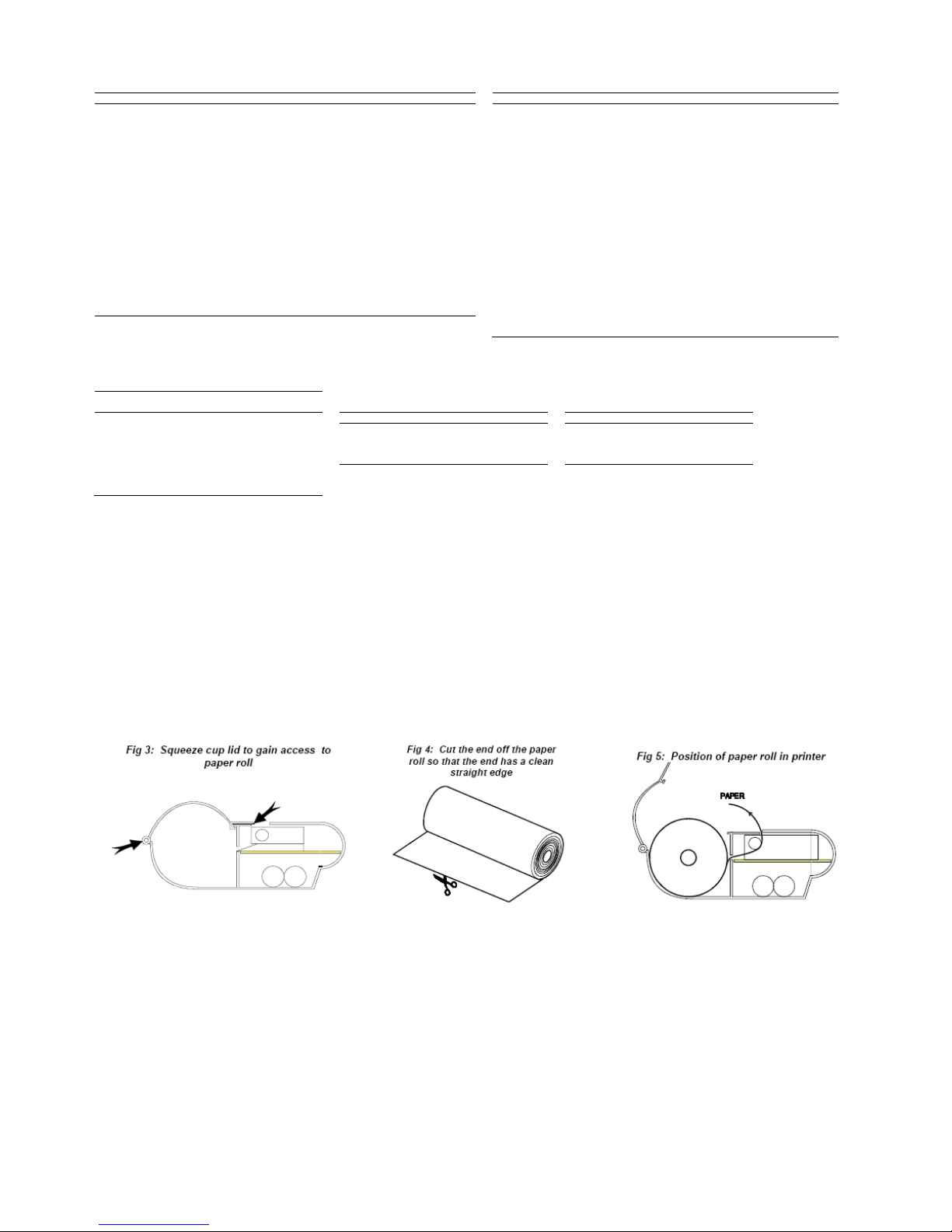
Check the batteries are sufficiently charged or that the power supply is correctly fitted and operational. Open the
paper cup lid and ensure that the roll is present and that there are no foreign objects inside the paper cup. Close
the lid, ensuring that the paper passes through the paper exit slot. Switch on the printer using the power switch
located on the left hand side of the printer. The Power indicator will light and the printer mechanism will reset.
Battery Charging
Connect the MCP9810-112 printer to the MPS power adapter and recharge the batteries as soon as the Status
LED lights continuously during printing.
If the batteries in the MCP9810-112 become exhausted, printing will become faint, erratic or not possible at all.
Turn off the MCP9810–112 and recharge the batteries for at least 1 hour before attempting further printing. The
MPS adapter cannot supply the full power requirements for the MCP9810-112 during printing, so the batteries must
be partially charged before printing is possible.
When the MCP9810-112 is first delivered there may be little or no charge in the printer’s batteries. The MCP9810-
112 should be turned off, connected to the MPS adapter and allowed to charge for 16 hours before it is used for
the first time.
It is permissible to leave the MCP9810-112 permanently connected to the MPS power adapter, constantly charging
the printer’s batteries between printouts. Alternatively the printer can be recharged from a 9-17VDC power supply,
ensure –ve centre pin connection.
Powe
r On Self Test
The self test procedure is initiated by turning on the printer
with the Paper Feed button pressed. Release the Paper
Feed button and the self test procedure will start. This will
check most of the printer functions, except for the serial
interface, i.e.
Printer mechanism
Control circuitry
Firmware version
DIP switch settings
Print Quality

3
Hardware Selectable Functions
These are set using the DIP switches and are only read with the printer when the printer is turned on.
SW 1: Print format Default settings
SW 2: Handshake protocol Print format 24cpl
SW 3: Baud rate Handshake protocol Hardware
SW 4: Baud rate Baud rate 9600
SW 5: Character height Character height Normal
SW 6: Character width Character width Normal
SW 7: Line spacing Extra blank lines Inserted
SW 8: Auto wake up Auto wake up Disabled
See below for a detailed explanation of the DIP switch settings (Fig 2: illustrates the default DIP switch settings).
To change the DIP switch settings, (make sure the printer is off before making any changes), use a pencil or similar
thin pointed object.
Auto Wake Up
The MCP9810-112 incorporates an auto wake up facility which minimises the printer’s power consumption. If auto
wake up is enabled, the printer will turn itself off after approximately five minutes of inactivity on the receive data
line. The printer will then wake up only when activity is detected on the receive line.
To wake the printer up, the user should ignore the status of the CTS line and send a NUL character (00H) to the
printer. The user should then wait at least 0.7 seconds for the printer to initialise before sending further data. Once
the printer has initialised, handshaking should be resumed.
Since the NUL character is non-printable, this procedure may be followed even if the printer is awake and will not
cause unwanted characters to be printed.
To enable the auto wake up facility, place DIP switch 8 in the UP position. If the switch is in the DOWN position the
printer will remain operational until turned off via the power switch.
If auto wake up is enabled, the printer may not turn on when power is applied via the power switch. Sending a NUL
character will cause the printer to power up normally.
Country Code Decimal Hex
USA ESC R 0
27 82 0 1B 52 00
France ESC R 1
27 82 1 1B 52 01
Germany ESC R 2
27 82 2 1B 52 02
UK ESC R 3
27 82 3 1B 52 03
Denmark I ESC R 4
27 82 4 1B 52 04
Sweden ESC R 5
27 82 5 1B 52 05
Italy ESC R 6
27 82 6 1B 52 06
Spain ESC R 7
27 82 7 1B 52 07
Japan ESC R 8
27 82 8 1B 52 08
Norway ESC R 9
27 82 9 1B 52 09
Denmark II ESC R 10
27 82 10 1B 52 0A
Software Selectable Functions
Bold
Underline
Double height
Double width
Graphics
Horizontal tab, plus setting
Form feed, plus setting
11 selectable international character sets (see right)
Reverse printing
Inverse printing
Reset
Barcodes
SW SW SW SW SW SW SW SW
1 2 3 4 5 6 7 8
24 Character per line ON
48 Charactere per line OFF
Software handshake ON
Hardware handshake OFF
1200 Bauds OFF
OFF
2400 Bauds ON ON
4800 Bauds OFF
ON
9600 Bauds ON OFF
Normal height ON
Double height OFF
Normal width ON
Double width OFF
Exta blank lines inserted
ON
No extra blank lines OFF
Auto wake up disabled ON
Auto wa
ke up enabled
OFF
Paper Selection
The setting of DIP switch 7 selects the type of
paper being used. If the MCP9810-112 is
loaded with label stock, SW7 must be placed in
the Up (OFF) position for correct operation to
take place.
The ‘ESC f ‘ sequence, which advances to the
next label, can only be used if SW7 is Up.
Since dual ply paper is less sensitive than
normal thermal paper, the ‘Esc !’ sequence
should be used to increase the print density to 4
when printing on dual ply (see Print Density for
details).

4
Control Codes and Escape Sequences
Function
Code Decimal Hex
Function
Code Decimal Hex
Horizontal tab
HT 9 09
Country select
ESC R n 27 82 n 1B 52 n
Line feed
LF 10 0A
Double width on
ESC W 1 27 87 1 1B 57 01
Form feed
FF 12 0C
Double width off
ESC W 0 27 87 0 1B 57 00
Carriage return
CR 13 0D
Compress bit image graphics
ESC n[d1]… n24[d24] 27 90 n1 … n24
1B 5A n1 … n24
Double width on
SO 14 0E
Print & feed paper
ESC d n 27 100 n 1B 64 n
Double width off
SI 15 0F
Lable advance
ESC f 27 102 1B 66
Cancel
CAN 24 18
Reversed on
ESC i 1 27 105 1 1B 69 01
Set print mode
ESC ! n 27 33 n 1B 21 n
Reversed off
ESC I 0 27 105 0 1B 69 00
Set barcode start position
ESC $ n1 n2 27 36 n1 n2 1B 24 n1 n2
Double height on
ESC w 1 27 119 1 1B 77 01
Set bit image (8 pin single density)
ESC * 0 n1 n2 [d] 27 42 0 n1 n2 [d] 1B 2A 00 n1 n2 [d]
Double height off
ESC w 0 27 119 0 1B 77 00
Set bit image (8 pin single density)
ESC * 1 n1 n2 [d] 27 42 1 n1 n2 [d] 1B 2A n1 n2 [d]
Inverse on
ESC { 1 27 123 1 2B 7B 00
Set bit image (24 pin single density)
ESC * 32 n1 n2 [d] 27 42 32 n1 n2 [d] 1B 1A 20 n1 n2 [d]
Inverse off
ESC { 0 27 123 0 1B 7B 00
Set bit image (24 pin single density)
ESC + 33 n1 n2 [d]
27 42 33 n1 n2 [d] 1B 1A 21 n1 n2 [d]
Set barcode height (1<n<225)
GS h n 29 104 n 1D 68 n
Underline on
ESC – 1 27 45 1 1B 2D 01
Print UPC-A barcode
GS k 0 [d] NULL 27 107 0 [d] 0 1D 6B 00 [D] 00
Underline off
ESC -0 27 45 0 1B 2D 00
Print UCP-E barcode
GS k 1 [d] NULL 27 107 1 [d] 0 1D 6B 01 [D] 00
Reset
ESC @ 27 64 1B 40
Print EAN13 barcode
GS k 2 [d] NULL 27 107 2 [d] 0 1D 6B 02 [D] 00
Set page length
ESC C n 27 67 n 1B 43 n
Print EAN8 barcode
GS k 3 [d] NULL 27 107 3 [d] 0 1D 6B 03 [D] 00
Set horizontal length
ESC D n 27 68 n 1B 44 n
Print Code 39 barcode
GS k 4 [d] NULL 27 107 4 [d] 0 1D 6B 04 [D] 00
Bold on
ESC G 27 71 1B 47
Print 2 of 5 barcode
GS k 5 [d] NULL 27 107 5 [d] 0 1D 6B 05 [D] 00
Bold off
ESC H 27 72 1B 48
Print codabar barcode
GS k 6 [d] NULL 27 107 6 [d] 0 1D 6B 06 [D] 00
Set bit image
ESC K n1 n2 [d] 27 75 n1 n2 [d] 1B 4B n1 n2 [d]
Print CODE 128 barecode
GS k 7 n [d] 27 107 7 n [d] 1D 6B 07 [D] 00
Set barecode magnification
2<n<4
GS w n 29 119 n 1D 77 n
Print Mode (ESC !)
Value
Bit Function 0 1
0 Print Density Bit 3 Bit 2 Character Font Bit 1 Bit 0
1
Character font
(see below) Light 1 (Default) 0 0 24 characters per line 0 0
2 2 0 1 48 characters per line 0 1
3
Print density
(see below) 3 (Label Default) 1 0 32 characters per line 1 0
4 Double height Cancelled Set Dark 4 1 1 Undefined 1 1
5 Double width Cancelled Set
6 Undefined
7 Undefined Cancelled Set
Replacing Paper Roll
If the paper roll needs replacing, open the paper cup lid (squeeze cup lid as shown in Fig 3) and remove the
remaining paper using the Paper Feed button, do not pull paper through the printer mechanism. Reel off a few
centimetres from a new roll of paper and check that the end has a clean straight edge (see Fig 4). Slide the leading
edge of the paper through the paper entry slot, with the leading edge of the paper feeding forwards from the bottom
of the roll, until you feel resistance. Press the paper feed button and feed the paper through the printer mechanism
(see Fig 5). Keep the paper feed button depressed until enough paper is fed through the printer mechanism to pass
through the paper exit slot. Sit the new paper roll in the paper cup and close the lid.
Should the paper become creased or out of line when feeding in a new roll, cut the end off the paper roll, feed out
the creased paper using the Paper Feed button, and reload ensuring the paper has a clean straight edge.
TAG Heuer
PROFESSIONAL TIMING
6A Louis-Joseph Chevrolet
2300 la Chaux-de-Fonds
Switzerland
Tel : 032 919 8000
Fax : 032 919 9026
info@tagheuer-timing.com
www.tagheuer-timing.com
Table of contents
Other TAG Heuer Printer manuals