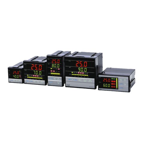
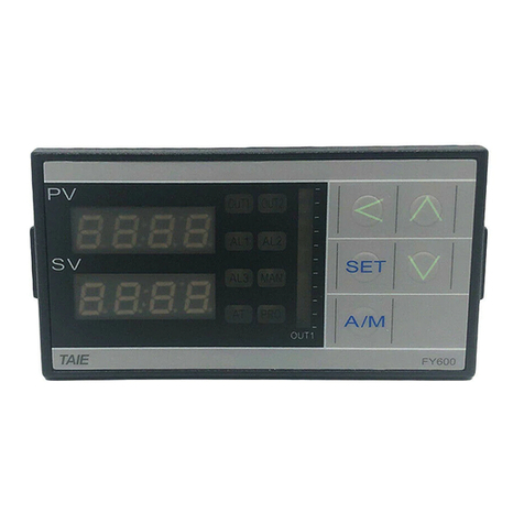
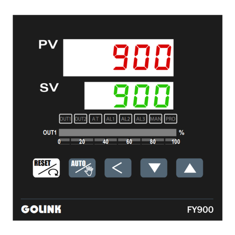
Taie FA Series User manual

0

1
CONTENT
1. Notice before start-up ..................................................................................................3
2. FU Series.....................................................................................................................4
2.1 Specifications......................................................................................................4
2.2 Outer Dimension.................................................................................................5
2.3 Terminal Wiring Diagram ....................................................................................6
2.4 Assembly & Wiring .............................................................................................7
3 FY Series ....................................................................................................................8
4. Terminal arrangement................................................................................................ 11
4.1 FY400 / FU48 Terminals ( 48mm x 48mm , DIN 1/16 )..................................... 11
4.2 FY600 Terminals ( 96mm x 48mm , DIN 1/8 )...................................................12
4.3 FY700 / FU72 Terminals ( 72mm x 72mm) .......................................................13
4.4 FY800 / FU86 Terminals ( 48mm x 96mm , DIN 1/8 ).......................................14
4.5 FY900 / FU96 Terminals ( 96mm x 96mm , DIN 1/4 ).......................................15
4.6 FY100 Terminals ( 175mm x 110mm ) ..............................................................16
4.7 FY101 Terminals ( 90mm x 90mm )..................................................................17
5. External dimension and panel cutout〈Unit:mm〉.................................................18
5.1 FY100...............................................................................................................18
5.2 FY101...............................................................................................................18
5.3 FY400~900 & FU48~96....................................................................................19
6. Parts description ........................................................................................................20
7. Operations .................................................................................................................21
7.1 Power On..........................................................................................................21
7.2 Change the Set Value (SV)...............................................................................21
7.3 Change the Alarm Value ...................................................................................21
7.4 Autotuning (AT).................................................................................................22
7.5 Programmable RAMP / SOAK (Only available for PFY model) ........................23
8. Operation levels.........................................................................................................24
8.1 Levels diagram .................................................................................................24
8.2 Lock function ....................................................................................................24
9. Parameters ................................................................................................................25
9.1 Level 1 (User Level) .........................................................................................25
9.2 Level 2 (PID Level) ...........................................................................................26
9.2.1 Level 2 parameters display /hiding condition ......................................26
9.2.2 Description of parameters....................................................................27
9.3 Level 3 (Input Level) .........................................................................................28
9.4 Level 4 (SET level) ...........................................................................................30
9.4.1 How to hide parameters (Use SET1~SET7) ........................................30
9.4.2 Special functions (Use SET8 / SET9 / SET0) ......................................31
9.4.3 Remote SV type selection ...................................................................32
9.4.4 Output mode selection (Use OUTY) ....................................................32
9.4.5 Modify caution .....................................................................................32
9.5 Program Level (Only displayed in programmable controller) .........................33
9.5.1 Description of parameters....................................................................33

2
9.5.2 Description of operation.......................................................................34
10. Input type table (INP1 selection)..............................................................................35
11. Alarm .......................................................................................................................37
11.1 Alarm time (ALT1/ALT2/ALT3) ........................................................................37
11.2 SETA...............................................................................................................37
11.3 Alarm mode (ALD1 / ALD2 / ALD3).................................................................38
12 Heater Break Alarm (HBA)........................................................................................39
12.1 HBA Wiring Example ......................................................................................39
12.2 HBA Function Description...............................................................................39
12.3 HBA setting procedure....................................................................................40
12.4 Parameters for HBA function ..........................................................................40
12.5 Activated conditions of HBA ...........................................................................41
12.6 Remarks .........................................................................................................41
12.7 CT specifications ............................................................................................42
12.7.1 SC-80T Specifications ..........................................................................42
12.7.2 SC-100T Specifications ........................................................................42
11.7.3 SC-80T Linear Diagram ........................................................................43
13. Error codes ..............................................................................................................44
14. Modify input type (“TC” “RTD”)......................................................................45
14.1 FY400~FY900 ................................................................................................45
14.2 FU48~96.........................................................................................................46
14.3 FY100~FY101 ................................................................................................46
15. Modify input type : Linear Input (mA ,V)...................................................................48
15.1 FY400~900 & FU48~96 Hardware:..............................................................48
15.2 FY100/101 Hardware:..................................................................................49
15.3 Calibration:...................................................................................................50
16. Modify Output type : Relay , SSR , 4~20mA............................................................51
17. Modify output mode: OUT1/ALARM, OUT1/OUT2 ..................................................51
18. Applications .............................................................................................................52
18.1 RAMP & SOAK...............................................................................................52
18.2 TTL Communication:SV output and RATE function .....................................53
18.3 1ψPhase angle control (By SCR module)......................................................54
18.4 1ψPhase angle control (By TRIAC) ...............................................................55
18.5 3ψPhase angle control (By DIODE/SCR module) .........................................56
18.6 1ψZero crossing control (By SCR module).....................................................57
18.7 1ψZero crossing control (By TRIAC) ..............................................................58
18.8 3ψZero crossing control (By SCR module).....................................................59
18.9 3ψZero crossing control (By TRIAC) ..............................................................60
18.10 3 wires proportional motor valve control .......................................................61
18.11 Wiring diagram of PC communication...........................................................62

3
1. Notice before start-up
FY series controller has got the CE approvals as below:
LVD:D/N EN61010-1
EMC:EN 55 022 1994 /A1:1995/ A2:1997
EN 61 000-3-2:1995 / -3-3:1995
EN 61 000-4-2:1995 / -4-3:1996 / -4-5:1995 / -4-6
1996 / -4-8:1993 / -4-11:1996/ EN 50 204:1995
Please confirm the specification of controller is to totally with your requirement before
using it, also read this manual in detail.
Danger
1. Danger! Electric Shock!
DON'T touch AC power wiring terminals when controller has been
powered!
Keep the power off until all of the wirings are completed!
Warning
1. Please confirm the AC power wiring to controller is correct, otherwise it would be
caused aggravated damage on controller. ( FY400 connecting with Pin 1 and 6,
FY100/FY101/FY600/700/800/900 with Pin 1 and 2).
2. Be sure to use the rated power supply (AC85~265V or DC24V), otherwise it would be
caused aggravated damage on controller.
3. Please confirm wires are connected with correct terminal (Input, Output).
4. Use M3 screw-compatible crimp-on terminals with an insulation sleeve, as shown
below
3.2mm 3.2mm
Torque : 0.4 N.m (4kgf.cm)
5. Avoid installing controller in following spaces:
I. A place where the ambient temperature may reach beyond the range
from 0 to 50℃
II. A place where the ambient humidity may reach beyond the range
from 20 to 90% RH.
III. A place where the controller likely to come into contact with water, oil,
chemicals, steam and vapor.
IV. A place where the controller is subject to interface with static
electricity, magnetism and noise.
6. For thermocouple (TC) input, use shield compensating lead wire.
7. For RTD input, use shield wires which have low resistance and no
resistance difference between the 3 wires.

4
2. FA Series
2.1 Specifications
zStandard Spec.
zGeneral Spec.

5
zControl Features
zInput Features
zOutput Features
zCommunication
zAlarms
2.2 Outer Dimension

6
2.3 Terminal Wiring Diagram

7
2.4 Assembly & Wiring
plug-in-out terminal M2.0 using “-”screwdriver fix terminal M2.6 using “+”screwdriver
Selecting suitable electric wire of AWG 16 ~ AWG22 Lock Screw torque: 0.3 N.m (3 kgf.cm)

8
3 FY / FU Series
zStandard spec.
Model FY400 /
FU48
FY600 FY700 /
FU72
FY800 /
FU86
FY900 /
FU96
FY100 FY101
Dimension 48X48mm 96X48mm 72X72mm 48X96mm 96X96mm 175X110mm 90X90mm
Supply voltage AC 85~265V,DC 15~50V (Option) AC 85~265V
Frequency 50 / 60 HZ
Power
consumption
approx
3VA
approx
4VA
approx
3VA
approx
4VA
approx
4VA
approx
4VA
approx
3VA
Accuracy 0.2 % FS ±1digit
Sample time 250ms
TC K , J , R , S , B , E , N , T , W5Re/W26Re , PLII , U , L
RTD PT100,JPT100,JPT50
mA dc 4~20mA ,0~20mA
mV / V dc 0~1V,0~5V,0~10V,1~5V,2~10V
-10~10mV,0~10mV,0~20mV,0~50mV,10~50mV
Input
Decimal point
position
0000 , 000.0 , 00.00 , 0.000
Available for linear input (mA / mV / V)
SPST type SPDT type SPST type SPDT type SPDT type SPDT type SPDT type
Relay
3A , 220V , electrical life:100,000 times or more (under rated load)
Voltage pulse For SSR drive. ON : 24V , OFF : 0V , max load current : 20mA
mA dc 4~20mA, 0~20mA. Maximum load resistance:560 Ω
Output 1
Voltage dc 0~5V , 0~10V , 1~5V , 2~10V . Max load current:20mA
Alarm 1 3A , 220V , electrical life:100,000 times or more (under rated load)
Control algorithm PID,PI,PD,P,ON / OFF(P=0),FUZZY。
PID range P: 0.0 ~ 200.0 %,I: 0~3600s,D: 0~900s
Isolation Output terminals(control output , alarm , transmission) and input
terminals are isolated separately
Isolated resistance 10MΩor more between input and case (ground) at DC 500 V
10MΩor more between output and case (ground) at DC 500 V
Dielectric strength 1000V AC for 1 minute between input terminal and case (ground)
1500V AC for 1 minute between output terminal and case (ground)
Operating
temperature
0~50℃
Humidity range 20~90%RH
Weight 150g 225g 225g 225g 300g 130g 80g
Display Height PV:7mm
SV:7mm
PV:7mm
SV:7mm
PV:14mm
SV:10mm
PV:7mm
SV:7mm
PV:14mm
SV:10mm

9
zOptional Spec.
Model FY400 /
FU48
FY600 FY700 /
FU72
FY800 /
FU86
FY900 /
FU96
FY100 FY101
Output 2 For heating and cooling control use.
Relay , SSR , 4~20mA , 0~20mA , 0~5V , 0~10V , 1~5V , 2~10V
Available Available Available Available Available Available
SPST type SPDT type SPST type SPDT type SPDT type SPDT type
Not
available
Alarm 2
3A , 220V , electrical life:100,000 times or more (under rated load)
Available Available Available Available AvailableNot
available SPST type SPST type SPST type SPST type SPST type
Not
available
Alarm 3
3A , 220V , electrical life:100,000 times or more (under rated load)
Display range of heater current : 0.0~99.9A , Accuracy : 1%FS
Included CT : SC-80-T (5.8mm dia , 0.0~80.0A)
or SC-100-T (12mm dia , 0.0~99.9A)
Heater Break Alarm
(HBA)
Alarm relay : AL1
Available for PV or SV transmission
Transmission
4~20mA , 0~20mA , 0~1V , 0~5V , 0~10V , 1~5V , 2~10V
Remote SV 4~20mA , 0~20mA , 0~1V , 0~5V , 0~10V , 1~5V , 2~10V
Protocol : MODBUS RTU , MODBUS ASCII , TAIE
RS232 , RS485 , TTL
Baud rate: 2400 , 4800 , 9600 , 19200 , 38400 bps.
Communication
Data bits : 8 , Stop bit : 1 or 2bit , Odd or Even parity.
Water/Dust proof IP65
zSpecial control output (OUT1)
Model FY400 /
FU48
FY600 FY700 /
FU72
FY800 /
FU86
FY900 /
FU96
FY100 FY101
1φzero crossing
control(1φSSR)
Available Not
available
Available Not
available
Available Not
available
Not
available
3φzero crossing
control(3φSSR)
Not
available
Available Not
available
Not
available
Motor valve control Available
1φphase angle
control(1φSCR)
Not
available
Available Available Not
available
3φphase angle
control(3φSCR)
Not available Available Not
available
Not
available

10
zProgrammable RAMP/SOAK
Model PFY400 PFY600 PFY700 PFY800 PFY900 PFY100 PFY101
Programmable
RAMP/SOAK
2 patterns with 8 segment each.
The 2 patterns can be linked together as 16 segments use.

11
4. Terminal arrangement
4.1 FY400 / FU48 Terminals ( 48mm x 48mm , DIN 1/16 )
AC 85~265V
DC 15 ~50V(Option)
A.Power Supply
Relay SSR mA,V
OUT1
G1
K1
G2
K2
OUT1
(1ΦZero Cross
Control)
Relay SSR mA,V
OUT2
2
3
CLOSE
OPEN
COM
OUT1
(Proportional Motor
Valve Control)
B.Control Output
mA,V RTD TC,mV
C.Input
2
3
AL 1
11
12
AL 1
13
14
AL 2
D.Alarm
TRS
E.Transmission
RS232
F.Communication
11
12
13
RD
SD
SG
RS485
11
12
Dx-
Dx+
TTL
11
12
13
RD
SD
SG
(Option)
(Use OUT1 & OUT2)
(Proportional Motor
Valve Control)
H.CT Input
CT
11
12

12
4.2 FY600 Terminals ( 96mm x 48mm , DIN 1/8 )
AC 85~265V
DC 15 ~50V(Option)
A.Power Supply
Relay SSR mA,V
OUT1
K2
G2
K1
G1
OUT1
(1ΦPhase
Angle Control)
Relay SSR mA,V
OUT2
6
7
CLOSE
OPEN
OUT1
(Proportional Motor
Valve Control)
B.Control Output
mA,V RTD TC,mV
C.Input
AL 1
6
7
AL 2
D.Alarm
TRS
E.Transmission
RS232
G.Communication
14
15
16
RD
SD
SG
RS485
14
15
Dx-
Dx+
TTL
14
15
16
RD
SD
SG
(Option)
1
2
3
4
5
6
7
8
9
10
11
12
13
14
15
16
17
18
19
20
7
8
9
10
COM
6
7
8
9
10
17
18
19
20
17
18
19
20
17
18
19
20
AL 3
12
13
Remote SV
F.Remote
14
15
H.CT Input
CT
14
15

13
4.3 FY700 / FU72 Terminals ( 72mm x 72mm)
AC 85~265V
DC 15 ~50V(Option)
A.Power Supply
1
2
3
4
5
6
7
8
9
10
11
12
13
14
15
16
17
18
19
20
21
Relay SSR mA,V
OUT1
G1
K1
G2
K2
OUT1
Relay SSR mA,V
OUT2
3
4
CLOSE
OPEN
OUT1
B.Control Output
mA,V RTD TC,mV
C.Input
3
4
AL 2
D.Alarm
TRS
E.Transmission
RS232
G.Communication
15
16
17
RD
SD
SG
RS485
15
16
Dx-
Dx+
TTL
15
16
17
RD
SD
SG
(Option)
COM
3
4
5
6
7
11
12
13
14
11
12
13
14
11
12
13
14
AL 1
18
19
Remote SV
F.Remote
9
10
5
6
7
21
15
16
17
18
20
PROT
G1
G2
OUT1
20
15
17
19
PROT
8
9
10
COM
NO
NC
(Proportional Motor
Valve Control)
(1ΦZero Cross
Control)
(1ΦPhase Angle
Control)
H.CT Input
CT
15
16

14
4.4 FY800 / FU86 Terminals ( 48mm x 96mm , DIN 1/8 )
AC 85~265V
DC 15 ~50V(Option)
A.Power Supply
Relay SSR mA,V
OUT1
K2
G2
K1
G1
OUT1
(1ΦPhase
Angle Control)
Relay SSR mA,V
OUT2
6
7
CLOSE
OPEN
OUT1
(Proportional Motor
Valve Control)
B.Control Output
mA,V RTD TC,mV
C.Input
AL 1
6
7
AL 2
D.Alarm
TRS
E.Transmission
RS232
G.Communication
14
15
16
RD
SD
SG
RS485
14
15
Dx-
Dx+
TTL
14
15
16
RD
SD
SG
(Option)
1
2
3
4
5
6
7
8
9
10
11
12
13
14
15
16
17
18
19
20
7
8
9
10
COM
6
7
8
9
10
17
18
19
20
17
18
19
20
17
18
19
20
AL 3
12
13
Remote SV
F.Remote
14
15
H.CT Input
CT
14
15

15
4.5 FY900 / FU96 Terminals ( 96mm x 96mm , DIN 1/4 )
AC 85~265V
DC 15 ~50V(Option)
A.Power Supply
Relay SSR mA,V
OUT1
Relay SSR mA,V
OUT2
6
7
B.Control Output
mA,V RTD TC,mV
C.Input
AL 1
6
7
AL 2
D.Alarm
TRS
E.Transmission
RS232
G.Communication
14
15
16
RD
SD
SG
RS485
14
15
Dx-
Dx+
TTL
14
15
16
RD
SD
SG
1
2
3
4
5
6
7
8
9
10
21
22
23
24
25
26
27
28
29
30
17
18
19
20
17
18
19
20
17
18
19
20
AL 3
39
40
Remote SV
F.Remote
14
15
G1
G2
OUT1
(1ΦZero
Cross Control)
40
31
33
39
PROT
G1
K1
G2
K2
OUT1
(1ΦPhase
Angle Control)
CLOSE
OPEN
OUT1
COM
6
7
8
9
10
36
31
32
33
34
35
PROT
RG1
RG2
TG1
TG2
OUT1
(3ΦZero
Cross Control)
40
31
33
35
37
39
PROT
G1
K1
G2
K2
OUT1
(3ΦPhase
Angle Control)
40
31
32
33
34
39
PROT
G3
K3
35
36 RS232
31
32
33
RD
SD
SG
RS485
31
32
Dx-
Dx+
( Remote SV )
11
12
13
14
15
16
17
18
19
20
31
32
33
34
35
36
37
38
39
40
(Proportional Motor
Valve Control)
H.CT Input
14
15
CT

16
4.6 FY100 Terminals ( 175mm x 110mm )

17
4.7 FY101 Terminals ( 90mm x 90mm )

18
5. External dimension and panel cutout〈Unit:mm〉
5.1 FY100
5.2 FY101

19
5.3 FY400~900 & FU48~96
FY400/
FU48
Y1
Y2
AT
AL
AL
PRO
1
250
50
44.5+0.5
44.5+0.5
65
70
FY600
96
50
90.5+0.5
44.5+0.5
111
70
FY700/
FU72 74
74
68.5+0.5
68.5+0.5
89
94
FY800/
FU86 96
50
44.5+0.5
90.5+0.5
65
116
FY900/
FU96 96
96
90.5+0.5
90.5+0.5
111
116
Other manuals for FA Series
1
This manual suits for next models
15
Table of contents
Other Taie Controllers manuals
Popular Controllers manuals by other brands

BRONKHORST
BRONKHORST EL-PRESS Quick installation guide

THORLABS
THORLABS MLC8 Series Operation manual

Dometic
Dometic 30AMP PWM user manual

J+J
J+J J2 L/H 10 manual

Cisco
Cisco AIR-WLC2106-K9 - Wireless LAN Controller... datasheet

Deep Sea Electronics Plc
Deep Sea Electronics Plc 720 Installation instructions and operators manual