Tait TB8100 User manual

Calibration Kit
User’s Manual
MB8100-90-00-806
June 2003
TB8100 base station


TB8100 Calibration Kit User’s Manual Contents i
Contents
Preface ..............................................................................................................iii
Enquiries and Comments ..................................................................iii
Updates of Manual and Equipment ...................................................iii
Copyright .........................................................................................iii
Disclaimer ........................................................................................iii
Typographical Conventions ..............................................................iii
Associated Documentation ...............................................................iii
Publication Record ..........................................................................iv
About TB8100 Calibration Kit ...........................................................................5
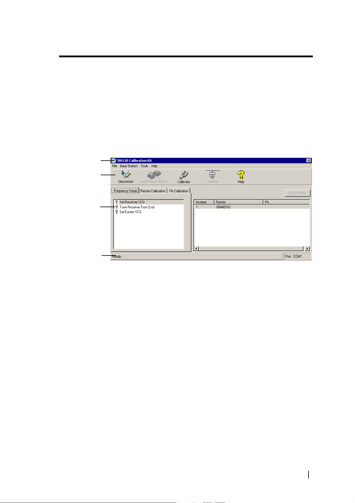
Tour of TB8100 Calibration Kit .............................................................5
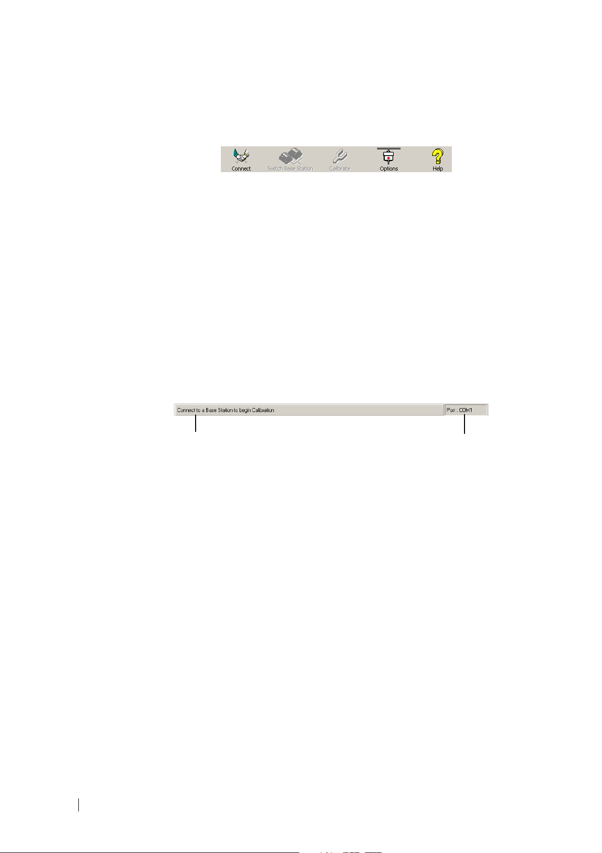
About the Toolbar ............................................................................6
About the Status Bar ..........................................................................6
Basic Tasks .........................................................................................................7
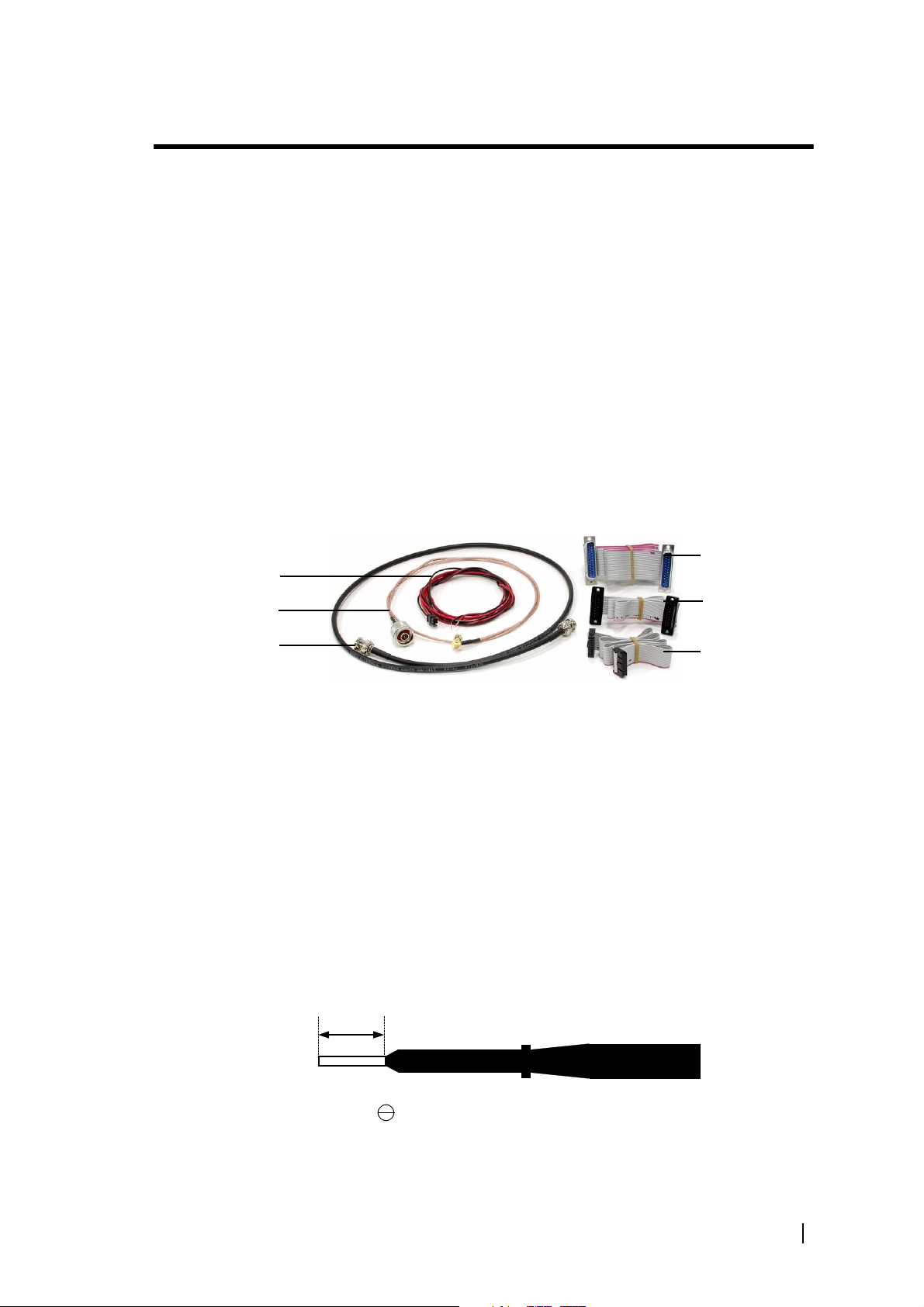
Equipment Required ..............................................................................7
Tuning Tool .....................................................................................7
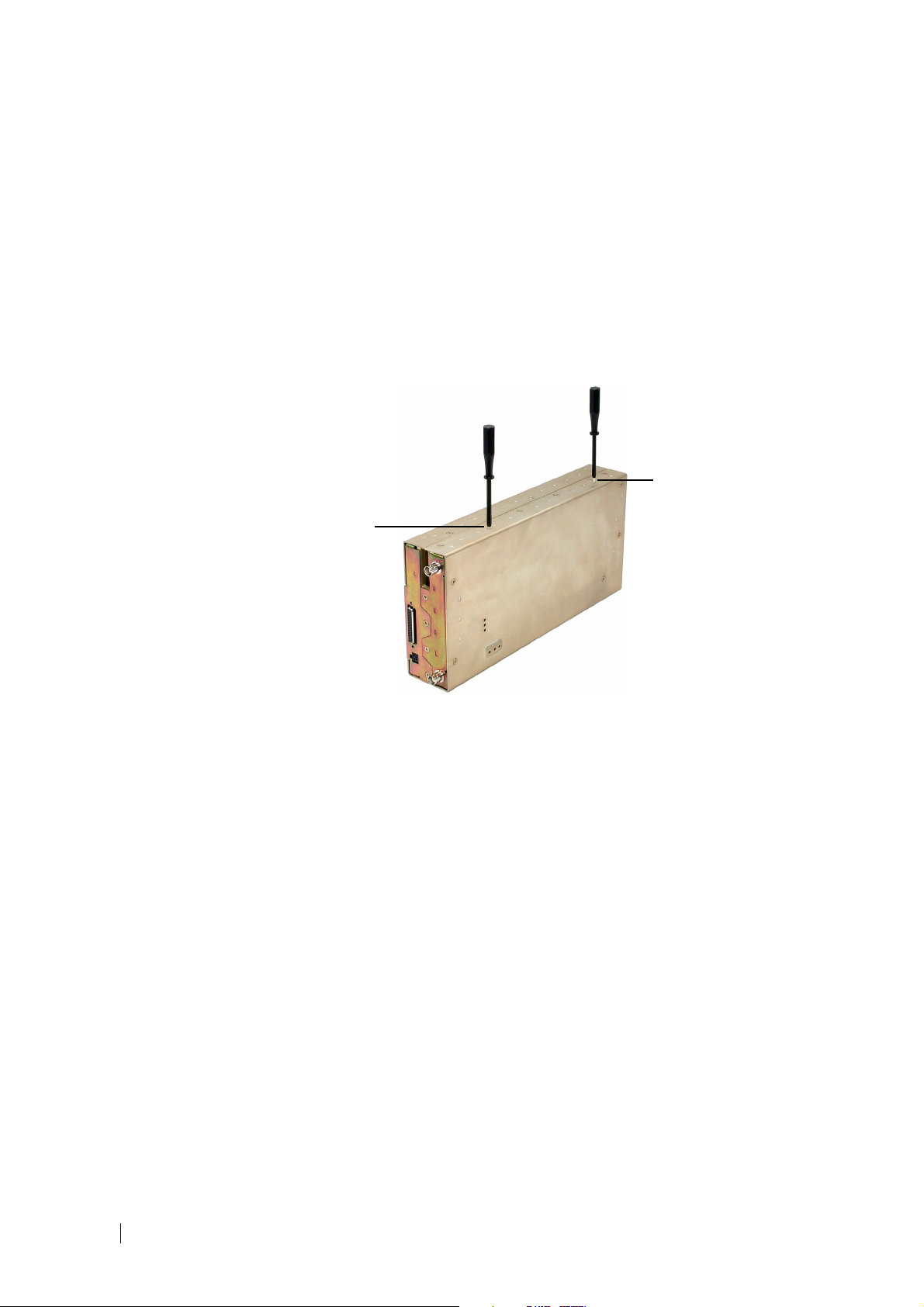
Reciter Tuning Holes .............................................................................8
Holes for Tuning the Receiver VCO and Exciter VCO ....................8
Holes for Tuning the Receiver Front-End .........................................8
Configuring TB8100 Calibration Kit ......................................................9
Selecting the Communications Port ...................................................9
Connecting to the Base Station ...............................................................9
Connecting to the Reciter Outside the Subrack ..............................10
Connecting to the Reciter/PA in the Subrack .................................11
Disconnecting from the Base Station/Reciter .......................................12
Basic Troubleshooting ..........................................................................12
Adjusting the Frequency Setup ......................................................................13
Adjusting the Receiver Lock Band .......................................................13
Tuning the Receiver ............................................................................14
Adjusting the Exciter Lock Band ..........................................................15
Calibrating the Reciter ....................................................................................17
Calibrating the Exciter ..........................................................................17
Automatically Tune the Frequency Control Loop (FCL) .................17
Calibrating the FCL Modulation .....................................................17
Calibrating the VCO Modulation ....................................................18
Calibrating the RSSI .............................................................................19
Audio Calibration .................................................................................21
Calibrating the Balanced Lines .........................................................21
Calibrating the Unbalanced Lines ....................................................22
Calibrating the TCXO .........................................................................23

ii Contents MB8100-90-00-806 © TEL 2003
Calibrating the Power Amplifier ................................................................... 25
Calibrating the PA Bias ........................................................................ 25
Calibrating the PA Power .................................................................... 26
Troubleshooting Tips ..................................................................... 27
Calibrating the Forward and Reverse Detector Bias Voltages ............... 27
Index .................................................................................. 29

TB8100 Calibration Kit User’s Manual Preface iii
Preface
Welcome to the TB8100 Calibration Kit User’s Manual. This manual provides
you with information about the Tait TB8100 Calibration Kit in PDF format.
You can view it online or print it if you want a paper copy. It describes how to
use Version 1.0 of the Calibration Kit.
Enquiries and Comments
Any enquiries regarding this manual as well as any comments, suggestions and
notifications of errors should be sent to support@taitworld.com, or addressed
to the Support Group Manager, Tait Electronics Limited, PO Box 1645
Christchurch, New Zealand.
Updates of Manual and Equipment
In the interests of improving the performance, reliability or servicing of the
equipment, Tait Electronics Limited reserves the right to update the equipment
or this manual or both without prior notice.
Copyright
All information contained in this manual is the property of Tait Electronics
Limited. All rights are reserved. This manual may not, in whole or in part, be
copied, photocopied, reproduced, translated, stored, or reduced to any
electronic medium or machine-readable form, without prior written
permission from Tait Electronics Limited. All trade names referenced are the
service mark, trademark or registered trademark of the respective
manufacturers.
Disclaimer
There are no warranties extended or granted by this manual. Tait Electronics
Limited accepts no responsibility for damage arising from use of the information
contained in the manual or of the equipment and software it describes. It is the
responsibility of the user to ensure that use of such information, equipment and
software complies with the laws, rules and regulations of the applicable
jurisdictions.
Typographical Conventions
‘File > Exit’ means ‘click File on the menu bar, then select Exit’.
Associated Documentation
■Online Help. The Calibration Kit also has online Help. It contains more or
less the same information as this manual. To view it, start the Calibration
Kit, then press F1 or click the Help icon on the toolbar. If you are in a dialog
box, click the Help button.
■TB8100 Installation Guide.
■TB8100 Installation and Operation Manual.
■TB8100 Service Manual (service centers only). A glossary of terms is available
in this manual.

iv Preface MB8100-90-00-806 © TEL 2003
■TB8100 Service Kit User’s Manual. The Service Kit is a Windows-based
software program that makes it easy to monitor and configure a Tait
TB8100 base station. You can also use it to carry out diagnostic tests on the
base station and to update its firmware. The Service Kit also has online Help.
Technical notes are published from time to time to describe applications for
Tait products, to provide technical details not included in manuals, and to offer
solutions for any problems that arise. Look for them on Tait's technical support
website. The following have been published or are in development:
■TN-742 Remotely Monitoring and Configuring the Tait TB8100.
■TN-743 Using the Tait TB8100 as a Talk-Through Repeater.
■TN-745 Using the Tait TB8100 in TaitNet Trunked Networks.
■TN-744 Using the Tait TB8100 as a Line-Connected Base Station.
Publication Record
Version Date Description
1.0 June
2003
First release of the manual for Version 1.0.0
of the Tait TB8100 Calibration Kit software.

TB8100 Calibration Kit User’s Manual Tour of TB8100 Calibration Kit 5
About TB8100 Calibration Kit
The TB8100 Calibration Kit is a Windows-based software program that allows
you to adjust the switching ranges of the receiver and transmitter, and flatten
the receiver response across the switching range.
Accredited Tait service centers can use the TB8100 Calibration Kit to calibrate
the reciter and the PA after servicing.
Tour of TB8100 Calibration Kit
When you start the TB8100 Calibration Kit, the main program window
appears.
The main program window has three tabs. The Calibration Wizards displayed
on each tab are only visible once you are connected to the reciter and/or base
station.
Frequency Setup
tab Shows the three Calibration Wizards that take you step-by-step through the
frequency setup.
ReciterCalibration
tab
Shows the seven calibration procedures that you can perform on the reciter.
The Calibration Wizard takes you step-by-step through the procedure you
have selected.
PA Calibration tab Shows the three calibration procedures that you can perform on the power
amplifier. The Calibration Wizard takes you step-by-step through the
procedure you have selected.
When the TB8100 Calibration Kit is connected to the reciter or base station,
you can view further details (such as module number, type, serial number, and
band) about the currently selected reciter and/or PA by clicking Show Details.
Menu bar
Toolbar
Calibration
Wizards
Status bar

6 Tour of TB8100 Calibration Kit MB8100-90-00-806 © TEL 2003
About the Toolbar
The toolbar gives you quick access to commonly used menu commands. For
example, instead of selecting Base Station > Calibrate, you can click the
Calibrate icon on the toolbar.
Connect Connects the TB8100 Calibration Kit to the base station and opens the
communication channels.
Switch Base
Station Lets you select another base station to calibrate if there are multiple base stations
in the rack.
Calibrate Runs the Calibration Wizard for the currently selected task.
Options Allows you to set the COM port and default calibration mode.
Help Opens the online help for the window you are currently in.
About the Status Bar
The status bar provides you with useful information that supplements the
display in the main window.
Miscellaneous messages COM port in use

TB8100 Calibration Kit User’s Manual Equipment Required 7
Basic Tasks
Before you start tuning and calibrating the base station, make sure that:
1. You have all the necessary equipment for the particular procedure(s) that
you want to perform, and
2. Your PC is connected to the base station or reciter.
If you want to define the switching range for a base station (if this has not
already been done), start here: “Adjusting the Frequency Setup” on page 13.
Equipment Required
You need the following equipment to tune and calibrate the base station:
■AC millivoltmeter (one with a differential input may be required for
“Calibrating the Balanced Lines” on page 21)
■Calibration test unit (CTU) (order code XBA0ST1)
■Calibration test kit (order code XBA0ST1-CBL) which comprises the
cables you will need to connect the CTU to the reciter/PA and the PC, and
a tuning tool
■Frequency counter
■Modulation meter
■RF attenuator (optional—depends on the setup)
■RF signal source
Refer to the individual procedures for equipment setup diagrams.
For more information about the calibration test unit, please refer to the TB8100
Service Manual.
Tuning Tool
The recommended tuning tool (for adjusting the front-end helical filters and
the VCOs in the reciter) is included in the calibration test kit (see Equipment
Required). It can also be ordered separately (order code 937-00012-00)
25-way cable
15-way TaitNet
cable
16-way cable
Power cable
RF cable
BNC to BNC
cable
20 mm
Bit shape:
Blade diameter: 2.2 mm Blade thickness: 0.4 mm

8 Reciter Tuning Holes MB8100-90-00-806 © TEL 2003
Reciter Tuning Holes
The following topics show the location of the holes for tuning the front-end
helical filters, and the VCO (Voltage Controlled Oscillator) in the reciter.
Adjusting the
frequency
When you tune the VCOs and the front-end helical filters, turn the tuning tool:
■Clockwise to reduce the frequency
■Anti-clockwise to increase the frequency
Holes for Tuning the Receiver VCO and Exciter VCO
The holes for tuning the receiver VCO and exciter VCO are shown below.
Holes for Tuning the Receiver Front-End
When running the Tune Receiver Wizard, you will need to tune the front-end
helical filters using the tuning tool as follows:
1. Insert the tuning tool into the first hole of the first triplet (see photograph).
2. Tune each of the resonators once to give the best response.
3. Do the same for the second triplet.
Exciter VCO
tuning hole
Receiver VCO
tuning hole

TB8100 Calibration Kit User’s Manual Configuring TB8100 Calibration Kit 9
4. Repeat this procedure as necessary to refine the response.
Configuring TB8100 Calibration Kit
Note: For information on computer system requirements, and
installing the TB8100 Calibration Kit, see the TB8100 Installation
and Operation Manual.
Selecting the Communications Port
Before you connect to a base station, you should first define the
communications (COM) port that you want to use.
To select the COM port
1. Select Tools > Options.
2. Select the port that you want to use from the COM Port list.
Note: The available COM ports are detected by the program and
appear in the list.
3. Click OK.
The COM port you selected is now shown on the status bar.
Connecting to the Base Station
Depending on the procedure you are performing, you may need to remove the
reciter from the subrack and connect to it via the calibration test unit (CTU).
The following tables summarise, for each procedure, whether or not you need
to remove a module from the subrack, and what equipment (in addition to a
PC and the TB8100 Calibration Kit software) you will need.
First triplet
Second triplet

10 Connecting to the Base Station MB8100-90-00-806 © TEL 2003
For instructions on how to connect to the reciter depending on whether it is
outside or inside the subrack, refer to:
■“Connecting to the Reciter Outside the Subrack” on page 10
■“Connecting to the Reciter/PA in the Subrack” on page 11
Reciter
Power Amplifier
Connecting to the Reciter Outside the Subrack
For the reciter calibration procedures that require access to the tuning holes,
you will need to remove the reciter from the subrack and connect to it as
follows.
Equipment ■Calibration test unit (CTU)
■An IBM compatible PC
■10-30 V DC power supply
■16-way I2C control bus cable
■RS-232 cable
Procedure Inside/Outside
Subrack Equipment Required
Adjusting receiver lock band Outside subrack Tuning tool, CTU
Tuning the receiver Outside subrack Tuning tool, CTU
Adjusting exciter lock band Outside subrack Tuning tool, CTU
Automatically tuning FCL Inside subrack None required
Calibrating the FCL modulation Outside subrack Tuning tool, CTU,
modulation meter, RF
attenuator (only if using PA)
Calibrating the VCO modulation Outside subrack Tuning tool, CTU,
modulation meter, RF
attenuator (only if using PA)
Calibrating the RSSI Inside subrack RF signal source
Calibrating the balanced lines Inside subrack CTU, AC millivoltmeter
Calibrating the unbalanced lines Inside subrack CTU, AC millivoltmeter
Calibrating the TCXO Inside subrack Frequency counter, RF
attenuator (only if using PA)
Procedure Inside/Outside
Subrack Equipment Required
Calibrating the PA bias Inside subrack None required
Calibrating the forward &
reverse detector bias voltages
Inside subrack None required
Calibrating the PA power Inside subrack None required

TB8100 Calibration Kit User’s Manual Connecting to the Base Station 11
Setup
To connect to the reciter
1. Remove the reciter from the subrack.
2. Set up the equipment as follows:
■Connect the reciter to the calibration test unit (CTU) using the I2C
control bus cable.
■Connect your computer to the CTU by plugging the RS-232 cable into
the programming port.
■Using the power cable supplied in the calibration test kit, connect the
reciter to the 10-30 V DC power supply, but do not power it up yet.
3. Start the TB8100 Calibration Kit program, and check that the correct COM
port is selected.
4. Click Connect to start the connection process.
5. When you see the “Waiting for logon prompt from Reciter” screen, power
up the reciter.
6. When the TB8100 Calibration Kit program has successfully connected to
the reciter, the Calibration Wizards are displayed in the main window.
You are now ready to tune and calibrate the reciter.
Connecting to the Reciter/PA in the Subrack
For the PA calibration procedures and the reciter calibration procedures that do
not require access to the tuning holes, you can leave the modules in the subrack
and connect your PC to the base station as follows.
Equipment ■An IBM compatible PC
■RS-232 cable
3
6
4
5
12
1PC 3Calibration test unit 5I2C control bus
2RS-232 cable 4Programming port 6Reciter

12 Disconnecting from the Base Station/Reciter MB8100-90-00-806 © TEL 2003
Setup
To connect to the base station
1. Connect your computer to the base station by plugging the RS-232 cable
into the serial port of the base station’s control panel.
2. Start the TB8100 Calibration Kit program, and check that the correct COM
port is selected.
3. Click Connect to start the connection process.
4. As soon as you see the “Waiting for logon prompt from Reciter” screen,
power up the base station.
5. When the TB8100 Calibration Kit program has successfully connected to
the base station, the Calibration Wizards are displayed in the main window.
You are now ready to calibrate the reciter or PA.
Disconnecting from the Base Station/Reciter
To disconnect from the base station or reciter before closing the program, select
File > Exit, or click Disconnect.
Important: Before disconnecting from the base station, ensure that
you have completed any calibration process that you have started. If
a calibration process is not completed, the base station could be left
in an uncalibrated state.
Basic Troubleshooting
Application Errors All application errors are recorded in a log file called “CalError.log”. The data,
time, location, and any other useful information is stored in this file, which may
be helpful when troubleshooting.
The file is saved in the Logfiles folder (..\Program Files\Tait Programming
Applications\TB8100 Service Kit\LogFiles), and stores up to 1000 of the most
recent logged items.
Verifying the
Software Version If you need to verify the version of the TB8100 Calibration Kit, select Help >
About.
4
1
3
2
1Base station 3RS-232 cable
2Serial port 4PC

TB8100 Calibration Kit User’s Manual Adjusting the Receiver Lock Band 13
Adjusting the Frequency Setup
Before the TB8100 base station is installed, connected, and configured, you
must prepare it for operation by adjusting the switching range of the reciter, and
flattening the receiver response across the base station’s switching range.
Note: If the required switching range for the base station has already
been defined, you don’t need to perform these procedures.
To prepare the base station for operation
1. Adjust the receiver lock band (optional)
2. Tune the receiver
3. Adjust the exciter lock band (optional)
Tip: Use the TB8100 Service Kit software to monitor the base
station and find out its current switching range.
Adjusting the Receiver Lock Band
The first step in preparing the TB8100 base station for operation is to adjust the
receiver lock band (switching range). The lock band is the range of frequencies
that the base station receiver or transmitter is calibrated to operate on.
Equipment ■Tuning tool
■Calibration test unit (CTU)
To adjust the receiver lock band
1. Ensure you are already connected to the reciter.
2. Select the Frequency Setup tab, and double-click Set Receiver VCO. The
Set Receiver VCO Wizard appears.
3. Enter the center frequency (which must be a multiple of 500 kHz) of the
lock band that you want to use, and click Next.
4. Insert the tuning tool into the receiver VCO tuning hole and adjust the
receiver VCO trimmer to center the receiver VCO on the frequency you
want, and then click Finish.
The lock band is now stored in the reciter, and the icon on the Frequency
Setup tab indicates that this task is complete. You will now need to tune the
receiver front end.

14 Tuning the Receiver MB8100-90-00-806 © TEL 2003
Tuning the Receiver
The second step in tuning the reciter frequency is to tune the receiver front
end. Tuning the receiver flattens the receiver’s response across its lock band
(switching range).
To help you do this, there is a graph of the RSSI readings in step two of the
Tune Receiver Front End Wizard. A number of RSSI readings are measured
across the 10 MHz band. These readings are then continually averaged to
produce the graph.
You should aim to achieve a response that looks something like this:
Equipment ■Tuning tool
■Calibration test unit (CTU)
Setup
To tune the receiver
1. Ensure you are already connected to the reciter.
2. Select the Frequency Setup tab, and double-click Tune Receiver Front
End. The Tune Receiver Front End Wizard appears.
3. Connect the CTU’s noise source to the receiver input, turn the noise source
on, and then click Next.
4. For each set of front-end helical filters, insert the tuning tool into each
tuning hole. (For the tuning sequence, refer to “Holes for Tuning the
Receiver Front-End” on page 8.) Click Coarse (fast) and roughly adjust
the front-end helical filters on the receiver. As you do so, observe the
graphical RSSI readings across the lock band.
Note: As the response gets flatter, you may find it helpful to select a
more sensitive scale, so that you can see the graphical reading in
more detail.
5. Once you have roughly tuned the front-end helical filters, click Fine
(slow). Continue to fine tune the front-end helical filters until the response
is flat in the middle of the lock band and not more than -1 dB at the ends
of the band (± 5 MHz).
3
2
1
1CTU 2Noise source 3Reciter

TB8100 Calibration Kit User’s Manual Adjusting the Exciter Lock Band 15
Note: When using the Fine (slow) setting, you may notice a slight
delay as the reading from tuning the front-end helical filters takes
approximately one second to appear on the graph.
6. Click Finish.
Once you have finished tuning the receiver, the icon on the Frequency
Setup tab indicates that this task is complete.
Adjusting the Exciter Lock Band
If you are preparing the base station for operation, adjusting the exciter lock
band is the third step in tuning the reciter. Otherwise, this procedure can be
performed independently of the other two calibration wizards on the
Frequency Setup tab. Adjusting the exciter lock band defines the range of
frequencies that the base station is able to transmit on.
Note: When performing this procedure, you don’t need to
terminate the exciter output port. An internal output pad means that
there is a good impedance match at this interface.
Equipment ■Tuning tool
■Calibration test unit (CTU)
To calibrate the exciter lock band
1. Ensure you are already connected to the reciter.
2. Select the Frequency Setup tab, and double-click Set Exciter VCO. The
Set Exciter VCO Wizard appears.
3. Enter the center frequency (which must be a multiple of 500 kHz) of the
lock band that you want to use, and click Next.
4. Insert the tuning tool into the exciter VCO tuning hole and adjust the
trimmer to roughly center the exciter VCO on the band you want. Click
Finish.
Once you have finished adjusting the exciter lock band, the icon on the
Frequency Setup tab indicates that this task is complete.

16 Adjusting the Exciter Lock Band MB8100-90-00-806 © TEL 2003

TB8100 Calibration Kit User’s Manual Calibrating the Exciter 17
Calibrating the Reciter
The reciter is fully calibrated in the factory, but if the reciter is serviced you may
need to perform the following procedures:
■Calibrating the Exciter
■Calibrating the RSSI
■Audio Calibration
■Calibrating the TCXO
These procedures can be done independently of each other, although it is
recommended that you tune the receiver before you calibrate the RSSI.
Important: It is recommended that only accredited service centers
and Tait engineers perform these procedures.
Advanced
Troubleshooting All the commands sent and received by TB8100 Calibration Kit are saved in a
file called “CCTM.log”. The date, time, command number, and parameters are
all stored in this file, which may be helpful when troubleshooting.
The file is saved in the Logfiles folder (..\Program Files\Tait Programming
Applications\TB8100 Service Kit\LogFiles), and stores up to 1000 of the most
recent logged items.
Calibrating the Exciter
You will need to calibrate the exciter if you have made component-level repairs
to it. There are three steps:
1. Auto-tune the FCL
2. Calibrate the FCL modulation
3. Calibrate the VCO modulation
Automatically Tune the Frequency Control Loop (FCL)
This is step one of calibrating the exciter.
Low frequencies (CTCSS and DCS) are modulated using the FCL (frequency
control loop). The FCL forms a loop that allows the reference frequency to be
modulated.
To automatically tune the FCL
1. Ensure you are already connected to the reciter.
2. Select the Reciter Calibration tab, and double-click FCL Auto Tuning.
The FCL Auto Tuning Wizard appears.
3. Click Calibrate to automatically tune the FCL.
The icon on the Reciter Calibration tab indicates that this task is complete.
You will now need to calibrate the FCL modulation.
Calibrating the FCL Modulation
This is step two of calibrating the exciter. Once you have auto-tuned the FCL,
you should calibrate the FCL modulation.
Equipment ■Tuning tool

18 Calibrating the Exciter MB8100-90-00-806 © TEL 2003
■Calibration test unit (CTU)
■Modulation meter
■RF attenuator (only required if you are using a PA)
Setup
To calibrate the FCL modulation
1. Ensure you are already connected to the reciter.
2. Select the Reciter Calibration tab, and double-click FCL Calibration. The
FCL Calibration Wizard appears.
3. Attach an appropriate Load and Modulation meter to the PA or exciter
output, set the meter to measure the RMS deviation, and then click Next.
(If you are using a PA, it will now transmit.)
4. Insert the tuning tool into the exciter VCO tuning hole and adjust the
trimmer to roughly center the exciter VCO on the band specified. Click
Next.
5. Use the slider to adjust the deviation at 30 Hz until it is 2121 Hz RMS (3 kHz
peak).
6. Select the 1 kHz Modulation Test and adjust the deviation at 1 kHz until it
is 2121 Hz RMS (3 kHz peak).
7. Repeat steps 6 and 7 until the modulation is 2121 Hz RMS at both 30 Hz
and 1 kHz.
8. Click Finish. (If you are using a PA, it will now stop transmitting.)
When you have finished calibrating the FCL modulation, the icon on the
Reciter Calibration tab indicates that this task is complete.
You will now need to calibrate the VCO modulation.
Calibrating the VCO Modulation
This is step three of calibrating the exciter.
Once you have tuned and calibrated the FCL, you should calibrate the VCO
at frequencies across the band.
Equipment ■Tuning tool
■Calibration test unit (CTU)
■Modulation meter
■RF attenuator (only required if you are using a PA)
1Reciter 3RF attenuator (only required if using a PA)
2PA (optional) 3Modulation meter
12
3
4
Other manuals for TB8100
12
Table of contents
Other Tait Accessories manuals