Tait T800 SL2 25W User manual

M8SL2-00-002-812 1
© Copyright Tait Electronics Limited August 2004. All rights reserved.
T800 SL2
Base Station Equipment
400 to 520MHz 25 Watt Continuous
Service Manual
August 2004
M8SL2-00-002-812

2M8SL2-00-002-812
© Copyright Tait Electronics Limited August 2004. All rights reserved.
TEL Contact Information
Corporate Head Office
Tait Electronics Ltd
175 Roydvale Avenue
P.O. Box 1645
Christchurch
New Zealand
Technical Support Enquiries
Phone: 64 3 357 9991
Fax: 64 3 358 0320
E-mail: s[email protected]om
Internet
http://www.taitworld.com
New Zealand
Tait Communications Ltd
540 Wairakei Road
P. O . B o x 11 8 5
Christchurch
Phone: 64 3 357 2750
Fax: 64 3 358 2029
E-mail: [email protected].nz
Australia
Tait Electronics (Aust) Pty Ltd
186 Granite Street
Geebung
Queensland 4034
P. O . B o x 6 7 9
Virginia
Queensland 4014
Australia
Phone: 61 7 3865 7799
Toll Free: 1 300 304 344
Fax: 61 7 3865 7990
E-mail: australia@taitworld.com
North America
Regional Head Office
Canada
Tait Mobile Radio Inc.
Unit 5, 158 Anderson Avenue
Markham
Ontario L6E 1A9
Canada
Phone: 1 905 472 1100
Toll Free: 1 800 890 TAIT (8248)
Fax: 1 905 472 5300
E-mail: canada@taitworld.com
USA
Toll Free: 1 800 890 TAIT (8248)
E-mail: usa@taitworld.com
Latin America
E-mail: latinamerica@taitworld.com
North Asia
Regional Head Office
Hong Kong
Tait Mobile Radio (HK) Ltd
Unit 2216, North Tower
Concordia Plaza
No. 1 Science Museum Road
Tsim Sha Tsui East
Kowloon
Phone: 852 2369 3040
Fax: 852 2369 3009
E-mail: hongkong@taitworld.com
Beijing
Tait Mobile Radio (HK) Ltd
Beijing Representative Office
Room 610, Tower 2
Beijing Henderson Centre
No. 18 Jianguomennei Da Jie
Doncheng District
Beijing
China 100005
Phone: 86 10 6518 6290
Fax: 86 10 6518 6296
E-mail: beijing@taitworld.com
Ta i w an
Tait Mobile Radio (Taiwan) Ltd
5Fl., No. 159, Keelung Road
Sec. 1
Taipei 110
Taiwan
Phone: 886 2 2768 6600
Fax: 886 2 2761 9970
E-mail: taiwan@taitworld.com
South East Asia
Regional Head Office
Singapore
Tait Electronics (Far East) Pte Ltd
491B River Valley Road
#09-02 Valley Point Office Tower
Singapore 248373
Phone: 65 471 2688
Fax: 65 479 7778
E-mail: singapore@taitworld.com
Thailand
Tait Mobile Radio Ltd
14/1 Suwan Tower
Third Floor
North Sathorn Road
Soi Saladaeng 1
Bangrak
Bangkok 10500
Thailand
Phone: 662 267 6290
Fax: 662 267 6293
E-mail: thailand@taitworld.com
Europe
Regional Head Office
United Kingdom
Tait Europe Ltd
Ermine Business Park
Ermine Road
Huntingdon
Cambridgeshire PE29 6WT
United Kingdom
Phone: 44 1480 52 255
Fax: 44 1480 411 996
E-mail: unitedkingdom@taitworld.com
France
Antenne Française
E-mail: france@taitworld.com
Germany
Zweigstelle Deutschland
E-mail: germany@taitworld.com
T800
T800

M8SL2-00-002-812 3
© Copyright Tait Electronics Limited August 2004. All rights reserved.
About This Manual
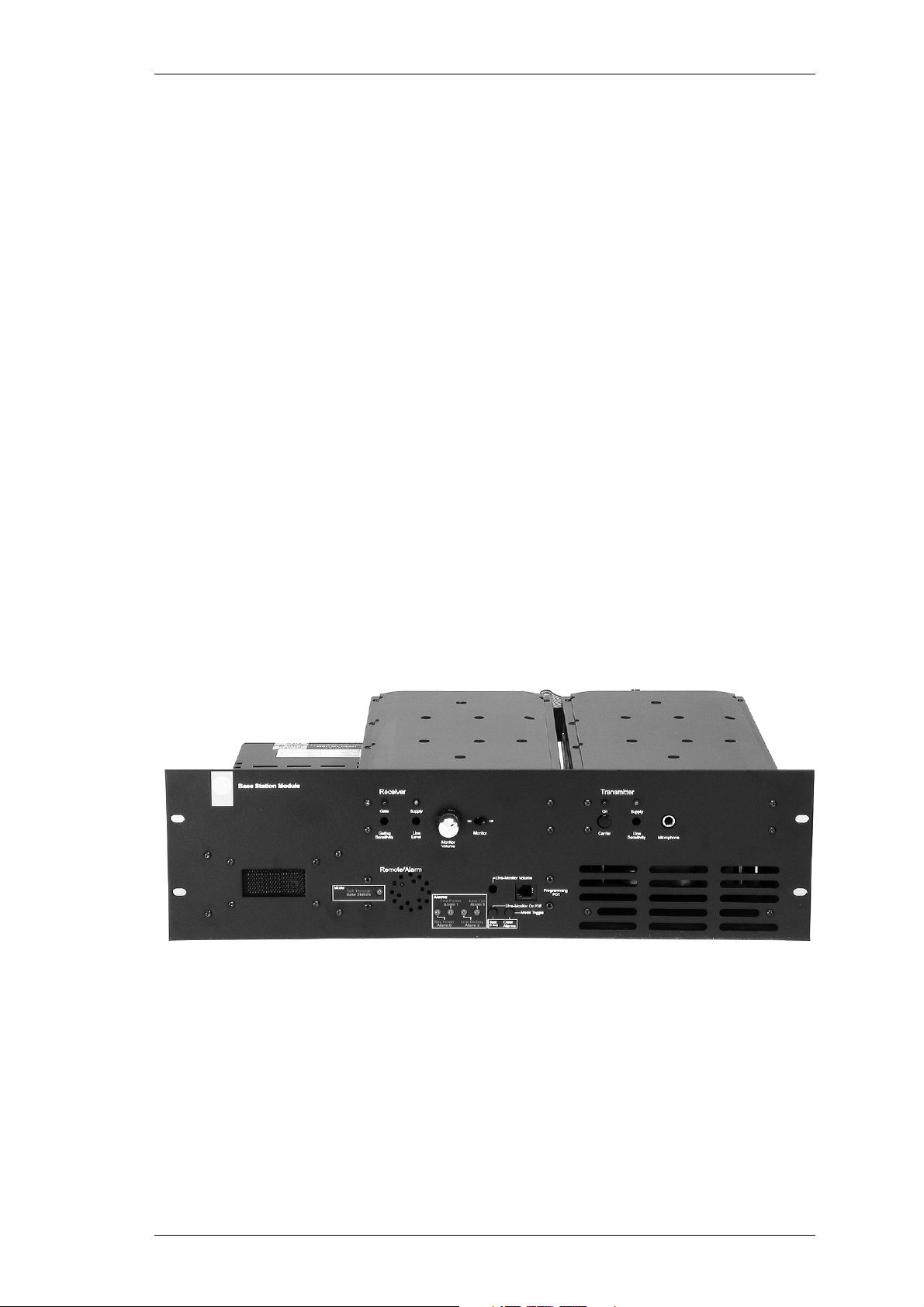
Scope This manual contains general, technical and servicing informa-
tion on T800 SL2 25W continuous base station which comprise
the following equipment:
Format We have published this manual in a ring binder so that “revision
packages” containing additional information pertaining to new
issues of PCBs can be added as required.
PCB Information PCB information is provided for all current issue PCBs, and is
grouped according to PCB. Thus, you will find the parts list,
grid reference index (if necessary), PCB layouts and circuit dia-
gram(s) for each individual PCB grouped together.
Errors If you find an error in this manual, or have a suggestion on how
it might be improved, please do not hesitate to contact Technical
Support, Tait Electronics Ltd, Christchurch, New Zealand (full
contact details are on page 2).
Updating Equipment and Manuals
In the interests of improving performance, reliability or servicing, Tait Electronics Ltd
reserve the right to update their equipment and/or manuals without prior notice.
Copyright
All information contained in this manual is the property of Tait Electronics Ltd. All
rights are reserved. This manual may not, in whole or part, be copied, photocopied,
reproduced, translated stored or reduced to any electronic medium or machine readable
form without prior written permission from Tait Electronics Ltd.
Ordering Tait Service Manuals
You can order additional copies of this service manual from your nearest Tait Dealer or
Customer Service Organisation. When ordering, make sure you quote the correct Tait
product code (“M” number). Note that only the latest issue of the manual will be availa-
ble for order.
T800 SL2 25W base
station
T855 receiver
T854 25W continuous transmitter
T803-02 tone remote (optional)
T800-23-0011 Power supply

4M8SL2-00-002-812
© Copyright Tait Electronics Limited August 2004. All rights reserved.
Publication Information
T800 SL2 Service Manual
Publication Date Product Code
June 2002
August 2004
M8SL2-00-001-812
M8SL2-00-002-812

M8SL2-00-002-812 5
© Copyright Tait Electronics Limited August 2004. All rights reserved.
1 T800 Product Codes
The T800 product code provides information about the model, type and options fitted,
according to the conventions described below
You can identify the unit’s type by checking the product code printed on a label on the
rear of the chassis (Figure 1.1 in Part A shows typical labels). You can further verify the
type by checking the placement of an SMD resistor in the table that is screen printed
onto the PCB..

6M8SL2-00-002-812
© Copyright Tait Electronics Limited August 2004. All rights reserved.
2 T800 SL2 Product Range
The following table lists the range of standard T800 types (i.e. no options fitted) availa-
ble at the time this manual was published. Consult your nearest Tait Dealer or Customer
Service Organisation for more information
T800 SL BSM Conventional Ordering Number System 18/11/02
L A 1 W B 0 0
System
Type
Frequency
Band
RF Output
Power
Channel
Spac ng
Power
Supply
Coax al
Relay /
Duplexer
Anc llary
Opt ons
L = T800 SL BSM (T800-56-X0XX)
1 =
4 =
*5 =
25 Watts
5 Watts
25 Watts (Cont)
0 =
4 =
6 =
7 =
8 =
9 =
No Anc llary Opt on
Mult -Channel Opt on (10 CH)
Cab net Desktop 3U (Blk)
Cab net Desktop 4U (Blk)
Cab net Transportable 6U (Blk)
Tone Remote Module
(T992-03-0002)
(T992-04-0002)
(T992-06-0002)
(T803-00-0000)
0 =
1 =
2 =
No Duplexer F tted
50 Watt Duplexer K t (T991-09-0001)+(T993-XX)
Coax al Relay K t (T800-09-0002)
If Duplexer tem code s set to (1), then Base/Repeater/
Sl ml ne Requ rement sheet must be completed. Th s s
requ red so correct Duplexer Frequency and Spac ng can be
calculated.
T991-09-0001 s a 1U 19" Tray for Duplexer f tt ng.
N =
M =
W =
12.5 kHz
20 kHz
25 kHz
A =
B =
C =
D =
E =
F =
P =
Q =
R =
66 - 88
136 - 156
148 - 174
400 - 440
440 - 480
480 - 520
800 - 870
860 - 910
890 - 960
(T82x-xx-02xx)
(T83x-1x-02xx)
(T83x-2x-02xx)
(T85x-1x-02xx)
(T85x-2x-02xx)
(T85x-3x-02xx)
(T88x-1x-02xx)
(T88x-2x-02xx)
(T88x-3x-02xx)
MHz
MHz
MHz
MHz
MHz
MHz
MHz
MHz
MHz
*
*
= Not Ava lable for US Market
B =
D =
BSM K t w th Power Supply
BSM K t w th External DC
(T800-56-X0X2)
(T800-56-X0X4)
1
1
2
2
3
3
4
7
5
6
5
67
4
* Only Ava lable n Frequency
Bands
400-520Mhz

M8SL2-00-002-812 7
© Copyright Tait Electronics Limited August 2004. All rights reserved.
Table of Contents
This manual is divided into nine parts as listed below, with each part being further sub-
divided into sections. There is a detailed table of contents at the start of each part and/
or section.
Part Title
A Introduction To Servicing
B T855 Receiver
C T854 Transmitter
D T803-02-9000 Tone Remote
E T850 VCO PCB Information
F T800-23-0011 Power Supply
G Installation and Configuration
H T800 Ancillary Equipment

8M8SL2-00-002-812
© Copyright Tait Electronics Limited August 2004. All rights reserved.

M8SL2-00-002-812 AI
© Copyright Tait Electronics Limited August 2004. All rights reserved.
Part A Introduction To Servicing
This part of the manual is divided into the sections listed below. These sections provide
some general and advisory information on servicing procedures.
Section Title Page
1
1.1
1.2
1.3
1.4
General
Additional Technical Information
Caution: CMOS Devices
Caution: Aerial Load
Caution: Beryllium Oxide and Power Transistors
1.1
1.1
1.1
1.2
1.2
2
2.1
2.2
2.3
2.3.1
2.4
Mechanical
Torx Recess Head Screws
Pozidriv and Philips Recess Head Screws
Disassembly/Reassembly
Receivers/Transmitters
Cover Screw Torques
2.1
2.1
2.2
2.3
2.3
2.3
3
3.1
3.1.1
3.1.2
3.2
3.3
Component Replacement
Leaded Components
Desoldering Iron Method
Component Cutting Method
Surface Mount Devices
Cased Mica Capacitors
3.1
3.1
3.1
3.1
3.2
3.2
Figure Title Page
1.1
1.2
2.1
2.2
Typical Product Code and Serial Number Labels
Typical Anti-static Bench Set-up
Torx Screw Identification
Pozidriv and Philips Screw and Screwdriver Identification
1.1
1.2
2.1
2.2

AII M8SL2-00-002-812
© Copyright Tait Electronics Limited August 2004. All rights reserved.

M8SL2-00-002-812 General A1.1
© Copyright Tait Electronics Limited August 2004. All rights reserved.
1 General
1.1 Additional Technical Information
If you have any questions about this manual or the equipment it describes, please con-
tact your nearest Tait Dealer or Customer Service Organisation. If necessary, you can get
additional technical help from Technical Support, Tait Electronics Ltd, Christchurch,
New Zealand (full contact details are on page 2).
When requesting information, please quote either the manual product code (e.g.
M8SL2-00-002-812), or the equipment product code, build revision number and serial
number which are printed on a label on the back of the product (as shown in Figure 1.1).
Figure 1.1 Typical Product Code and Serial Number Labels
If you require information about a particular PCB, please quote the full PCB internal
part number (IPN) which is screen printed onto the top side of the board (refer to the
appropriate PCB Information section in this manual for more details).
1.2 Caution: CMOS Devices
This equipment contains devices which are susceptible to damage from static charges.
You must handle these devices carefully and according to the procedures described in
the manufacturers’ data books.
We recommend you purchase an antistatic bench kit from a reputable manufacturer and
install and test it according to the manufacturer’s instructions. Figure 1.2 shows a typi-
cal antistatic bench set-up.
You can obtain further information on antistatic precautions and the dangers of electro-
static discharge (ESD) from standards such as ANSI/ESD S20.20-1999 or
BS EN 100015-4 1994.

A1.2 General M8SL2-00-002-812
© Copyright Tait Electronics Limited August 2004. All rights reserved.
Figure 1.2 Typical Anti-static Bench Set-up
1.3 Caution: Aerial Load
The equipment has been designed to operate safely under a wide range of aerial loading
conditions. However, we strongly recommend that the transmitter should always be
operated with a suitable load to prevent damage to the transmitter output power stage.
1.4 Caution: Beryllium Oxide and Power Transistors
The RF power transistors in current use all contain some beryllium oxide. This sub-
stance, while perfectly harmless in its normal solid form, can become a severe health
hazard when it has been reduced to dust. For this reason the RF power transistors
should not be broken open, mutilated, filed, machined, or physically damaged in any
way that can produce dust particles.
Common pointground
(building ground or
mains ground via
1MΩseries resistor)
conductive wrist strap dissipative rubber
bench mat

M8SL2-00-002-812 Mechanical A2.1
© Copyright Tait Electronics Limited August 2004. All rights reserved.
2Mechanical
2.1 Torx Recess Head Screws
Torx recess head screws are becoming the standard screw head type in all T800 SL2
equipment, with Pozidriv and Philips recess head screws being used in fewer applica-
tions.
The Torx recess head has the advantage of improved screwdriver tip location, reducing
the chances of screw head damage caused by the driver tip rotating within the recess. In
addition, using a ball-tip Torx screwdriver allows you to drive a Torx head screw with
the driver on a slight angle, which can be useful in situations where access is restricted.
It is important that you use the correct Torx screwdriver tip:
M3 screws T10
M4 screws T20
Figure 2.1 below shows a typical Torx recess head screw (actual hardware may differ
slightly from this illustration due to variations in manufacturing techniques).
Figure 2.1 Torx Screw Identification
"star” shaped recess with
six internal notches

A2.2 Mechanical M8SL2-00-002-812
© Copyright Tait Electronics Limited August 2004. All rights reserved.
2.2 Pozidriv and Philips Recess Head Screws
Pozidriv and Philips recess head screws will continue to be used in T800 SL2 equipment
in a few special applications. It is important that you use the correct type and size
screwdriver for each screw type to avoid damaging the screw head.
It is particularly important that you do not use Philips screwdrivers on Pozidriv screw
heads as the tapered driving flutes of the Philips screwdriver do not engage correctly
with the parallel-sided slots in the Pozidriv screw head. This can result in considerable
damage to the screw head if the screwdriver tip turns inside the recess.
Note: If you find you need excessive downwards pressure to keep the screwdriver
tip in the Pozidriv screw head, you are probably using the wrong type and/
or size screwdriver.
Figure 2.2 below shows the main differences between typical Pozidriv and Philips screw
heads and screwdriver tips (actual hardware may differ slightly from these illustrations
due to variations in manufacturing techniques).
Figure 2.2 Pozidriv and Philips Screw and Screwdriver Identification
driving flutes with
parallel sides
driving flutes with
tapered sides
Pozidriv Philips
internal notches
"star" markings
between slots
no special markings
slots with parallel sides
slots with tapered sides
ridges between
driving flutes

M8SL2-00-002-812 Mechanical A2.3
© Copyright Tait Electronics Limited August 2004. All rights reserved.
2.3 Disassembly/Reassembly
2.3.1 Receivers/Transmitters
To carry out alignment or change option links, you need to remove only the top cover,
i.e. the one on the opposite side to the main D-range connector (D-range 1/PL100).
You need to remove the bottom cover to:
• access transmitter RF power transistors and many SMD components
• change solder blob links
• fit test leads to circuit block access points.
2.4 Cover Screw Torques
Receivers/Transmitters … 1.36Nm/12in.lbf.

A2.4 Mechanical M8SL2-00-002-812
© Copyright Tait Electronics Limited August 2004. All rights reserved.

M8SL2-00-002-812 Component Replacement A3.1
© Copyright Tait Electronics Limited August 2004. All rights reserved.
3 Component Replacement
3.1 Leaded Components
Whenever you are doing any work on the PCB that involves removing or fitting compo-
nents, you must take care not to damage the copper tracks. The two satisfactory meth-
ods of removing components from plated-through hole (PTH) PCBs are detailed below.
Note: The first method requires the use of a desoldering station, e.g. Philips SBC
314 or Pace MBT-100E.
3.1.1 Desoldering Iron Method
Place the tip over the lead and, as the solder starts to melt, move the tip in a circu-
lar motion.
Start the suction and continue the movement until 3 or 4 circles have been com-
pleted.
Remove the tip while continuing suction to ensure that all solder is removed from
the joint, then stop the suction.
Before pulling the lead out, ensure it is not stuck to the plating.
If the lead is still not free, resolder the joint and try again.
Note: The desoldering iron does not usually have enough heat to desolder leads
from the ground plane. Additional heat may be applied by holding a solder-
ing iron on the tip of the desoldering iron (this may require some additional
help).
3.1.2 Component Cutting Method
Cut the leads on the component side of the PCB.
Heat the solder joint sufficiently to allow easy removal of the lead by drawing it
out from the component side: do not use undue force.
Fill the hole with solder and then clear with solderwick.

A3.2 Component Replacement M8SL2-00-002-812
© Copyright Tait Electronics Limited August 2004. All rights reserved.
3.2 Surface Mount Devices
Caution: Surface mount devices (SMDs) require special storage, handling,
removal and replacement techniques. This equipment should be serv-
iced only by an approved Tait Dealer or Customer Service Organisa-
tion equipped with the necessary facilities. Repairs attempted with
incorrect equipment or by untrained personnel may result in perma-
nent damage. If in doubt, contact your nearest Tait Dealer or Customer
Service Organisation.
3.3 Cased Mica Capacitors
Cased mica capacitors can be removed by heating the top with a heavy-duty soldering
iron and gently lifting the capacitor off the PCB with a solder-resistant spike or equiva-
lent.

M8SL2-00-002-812 BI
© Copyright Tait Electronics Limited August 2004. All rights reserved.
Part B T855 Receiver
This part of the manual is divided into six sections, as listed below. There is a detailed
table of contents at the start of each section.
Section Title
1 General Information
2 Circuit Operation
3 Initial Tuning and Adjustment
4 Functional Testing
5 Fault Finding
6 PCB Information

BII M8SL2-00-002-812
© Copyright Tait Electronics Limited August 2004. All rights reserved.
Table of contents
Other Tait Accessories manuals