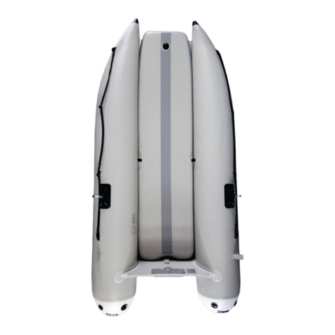
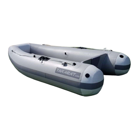
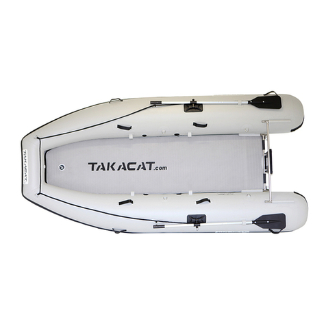
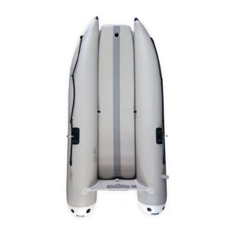
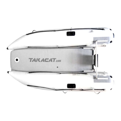
TAKACAT T LX Series User manual

© TAKACAT GmbH - Friedel Hacker (Dipl.-Ing.) Page 1
Owner's Manual V1 - T260LX to T420LX
Manufacturer: AIR YACHT Ltd - 3 Owens Rd, Epsom - Auckland 1023 - New Zealand - www.takacat.com
Please be sure to observe the information on the type plate attached to the rear-view mirror plate and the
instructions on the inside of the driving tubes.
Summary:
Introduction …………………………………………………………………………………………………………………………………………2
Delivery Package …………………………………………………………………………………………………………………………….3
Assempling …………………………………………………………………………………………………………………………………………3
Dismantling …………………………………………………………………………………………………………………………………………6
Towing + anchoring …………………………………………………………………………………………………………………………….7
Drainage system ……………………….……………………………………………………………………………………………………7
Important notes ………………………………………….…………………………………………………………………………………7
Specifications …………………………………………………………………………………………………………………………….9
Importer …………………………………………………………………………………………………………………………..11

© TAKACAT GmbH - Friedel Hacker (Dipl.-Ing.) Page 2
Introduction:
This manual has been compiled to enable you to operate your boat safely and with pleasure. It contains
details about the vessel itself, the accessories supplied or installed and its equipment, as well as
information about its operation. Please read it carefully and familiarise yourself with the vessel before
using it.
This boatmaster's manual is not a course in boat safety or seamanship. If this is your first vessel or if you
have changed to a type of vessel you are not familiar with, for your own safety and convenience, please
ensure that you acquire knowledge of the handling and operation of the vessel before taking command.
Your dealer or the national sailing or powerboat association or yacht club will be happy to advise you about
local yacht schools or recommend experienced instructors.
Make sure that the expected wind and sea conditions are in accordance with the design category of your
vessel and that you and your crew are able to handle the vessel under these conditions. Please refer to
"Specifications" at the end of this manual for the design category of the corresponding models.
This manual is not a detailed maintenance or troubleshooting guide. If you encounter any difficulties,
please contact the boat builder or his representative. If a maintenance manual is provided, use it for
maintenance of the boat.
Only use trained and competent personnel for maintenance, repairs or modifications. Changes that may
affect the safety characteristics of the vessel must be assessed, carried out and recorded by specialists. The
boat builder cannot be held responsible for any changes that he has not agreed to.
Some countries require a driving licence or authorisation or have special regulations.
Always maintain your watercraft properly and take into account the wear and tear that occurs over time
and through frequent use or improper use of the watercraft.
Any watercraft, regardless of how strong it is built, can suffer serious damage through improper handling.
This is not compatible with safe boat handling. Always adjust the speed and direction of the watercraft to
the sea conditions.
If your vessel is equipped with a life raft, read its operating instructions carefully. The vessel should be
equipped with the appropriate safety equipment (life jackets, safety belts, etc.) according to the type of
vessel, weather conditions, etc. This equipment is compulsory in some countries. The crew should be
familiar with the use of all safety equipment and manoeuvring in emergency situations (man overboard
recovery, mooring, etc.). Sailing schools and clubs regularly organise training courses.
All persons should wear a portable buoyancy aid (life jacket/personal buoyancy aid) when on deck. It
should be noted that in some countries there are legal requirements that require that a buoyancy aid be
worn at all times in accordance with national regulations.
PLEASE KEEP THIS MANUAL IN A SAFE PLACE AND GIVE IT TO THE NEW OWNER WHEN YOU SELL
THE BOAT.
•WARNING - When loading the vessel, never exceed the maximum recommended payload.
Loading must always be carried out with care, distributing loads appropriately to maintain design
trim. Heavy loads must be placed as low as possible.
•WARNING - Do not exceed the maximum recommended number of people. Regardless of the

© TAKACAT GmbH - Friedel Hacker (Dipl.-Ing.) Page 3
number of persons on board, the total weight of persons and equipment must never exceed the
recommended maximum payload.
•WARNING - CAUTION FOR ABANDONING WIND and CURRENTS.
•Attention - For towing the boat, only the appropriate tow rings in the bow and stern areas are to
be used. Failure to do so may result in damage to the boat hull.
•Caution - There should be no loose objects in the boat. Always make sure that all objects,
including any paddles, anchors etc. are safely stored in a suitable bag or pouch and that this is
additionally secured.
Delivery Package
In the scope of supply of the Takacats the following components are contained which are to be carried
along: rolling seat or flat seat, rudder or paddle, spare valve, repair kit incl. emergency glue, hand pump,
mooring line.
Depending on the engine and country regulations, additional items such as emergency signals, fire
extinguisher, driving lights, anchor, bilge pump, etc. must be carried. A spray bottle with some rinsing water
is also sometimes helpful, e.g. for the transom tubes or for cleaning the hoses and the high pressure floor.
Please inform yourself in your own interest about the country-specific features.
Assempling
Step 1:
Remove the hose set from the carrying bag and lay it spread out on a flat surface. Check that the valve plugs
are in the filling position and inflate the hoses slightly.
Step 2:
Spray the longitudinal tubes of the lower transom mount with some soap water or if not available moisten
the longitudinal tubes with some water. Insert the lower transom mount into the lower sockets from the
outside, with the two fixing tongues for the transom plate positioned "outward-up". Make sure that the left
and right wheel mounts do not scrape the tube fabric until the tube is completely filled. You can, for
example, place a cloth as protection between the hose and the wheel mountings.
Applies only to open transom - spray the longitudinal tubes of the upper transom mount with some soap
water or if not available moisten the longitudinal tubes with some water. Then insert the upper transom
mount from the inside into the two upper guides, the two fixing tongues for the transom plate must be
positioned "outside-down".
ATTENTION (only applies to open transom):
Please do not use brute force when installing the transom mounts. If the transom mount cannot be inserted
easily, moisten the tubes and the tube guides with some soapy water or rinse water.
Never use acidic oils, grease or sunscreen etc.
Step 3:
Set the valve pins of all inlet valves to pump position. Insert the HALKEY ROBERTS of the air pump hose into
the corresponding inlet valves one after the other, lock them correctly and pump up
the carry/drive hoses of the Takacat to approx. 220 mbar. For Takacats with several hose chambers (T380LX
and T420LX), first pump up the rear hose chambers to approx. 150 mbar and then the front hose
chambers to approx. 220 mbar (If individual chambers of multi-chamber hoses are pumped up directly at
full pressure, the inner hose bulkhead may tear under certain circumstances - when folding multi-
chamber boats, first relieve all hose chambers of pressure and never empty just one chamber
completely). The pressure in the front hose chambers is then equalised with the rear hose chambers via the

© TAKACAT GmbH - Friedel Hacker (Dipl.-Ing.) Page 4
220 mbar of the front hose chambers. In practice it has been shown that 220 mbar is completely sufficient.
The maximum chamber pressure for the carrying/drive hoses must not exceed 250 mbar.
When the pumping process is finished, you must close the valves with the corresponding protective covers.
The hose chambers are equipped with safety overpressure valves so that any excess pressure can be
compensated. With the pressure gauge included in the delivery you can check the correct filling, or you can
use an electric pump with corresponding adjustment possibilities. Always make sure that the valve adapter
is correctly locked and keep a proper distance during the pumping process, so that no injuries are caused if
the air hose should jump off!
Note - Fixation seam:
When you have inflated the driving tubes you will see a split seam. This seam is
not a defect but a so-called fixation seam, which is set during the production
process so that the connecting bottom can be glued at right angles to the two
driving hoses. When inflating, this fixation seam opens up and the separated
stitch threads can be seen, which rub away over time.
Step 4 (only applies to open transom):
4 Allen screws transom plate: Fasten the transom plate to the four fastening tongues with the supplied
screws. The screws are guided from the inside to the outside through the fixing tongues into the transom
plate with a fitted retaining ring and a fitted washer, and are first screwed by hand into the press-in nuts at
the rear. Please make sure that the screws can be screwed into the nuts easily. Please make sure that there
is a retaining ring and a washer under each screw head. The final fixing is done with the help of the supplied
Allen wrench. Tighten the screws well by hand, do not use brute force when screwing them together.
Rear view mirror plates with central screw and ring nut: Place the smaller rear view mirror plate with the
type plate on the stainless steel mountings of the transom tubes from the front. Then hold the larger
transom plate from behind against the transom tubes and insert the central fastening nut with a slipped on
spacer through the fastening hole. Coat the last threads of the fastening screw e.g. lightly with transparent
Liqui Moly lubricant. Then tighten the ring nut with a spacer washer by hand. Fix the central transom
mounting with a 17 mm socket wrench and a counter rod for the ring nut. Do not use brute force when
screwing it on. Greasing the threads serves to prevent the threads of the screw and ring nut from sticking,
which V4A stainless steel tends to do. You can find a video illustration at:
https://www.youtube.com/watch?v=BTRTezVRcF0&feature
When using a Torqeedo Travel 503, 1003 or 1103, a distance plate made of wood or plastic must be placed
between the inner transom plate and the pressure plates of the toggle screw connection so that the toggle
screw connections do not press into the upper transom rod. The minimum dimensions of the distance plate
are 140 x 40 x 10mm (width/height/depth).
When installing an outboard (short shaft), it is essential to ensure that the support plates of the toggle
fittings of the outboard mounting do not press in the upper transom rod and cause structural damage. If
necessary use a spacer plate (applies only to open transom). Camp3 (www.camp3.eu) offers a plastic
distance plate which can be screwed under the stainless steel plate of the inner transom plate. Outboards
with long shaft or extra long shaft must not be used. The transom tubes must not be used as towing
brackets. Only the tow rings in the stern and bow area are used for towing. In order to avoid damage, it is
essential to ensure gentle gas changes.
Step 5:
Place the two black floor end tabs on the left and right over the lower transom mount and close the
respective Velcro fasteners. The middle bottom flap is used for drainage and is simply led outwards below
the transom mount.

© TAKACAT GmbH - Friedel Hacker (Dipl.-Ing.) Page 5
Step 6:
Models with side floor bow tip fixation: Remove the high pressure floor and place it snugly between the
support tubes and the transom area. Ensure that the middle bottom end tab is between the transom plate
and the high pressure floor. Inflate the high pressure floor to at least 600 mbar (max. 689 mbar) and make
sure that it is correctly seated and positioned between the support hoses. At the end of the pumping
process, close the valves with the corresponding protective covers. Finally, lash the bow tips to the high-
pressure bottom using the supplied straps and the corresponding eyelets.
You can find an illustrative video under: https://www.youtube.com/watch?v=fO7p9GyMDck
Models with central floor bow point fixation: Place the high pressure floor between the driving hoses. The
correct position is achieved when the two fixing rings can be inserted at right angles through the two slots
of the connecting floor. Pump up the high pressure floor to at least 600 mbar (max. 689 mbar) and make
sure that the floor is correctly seated and positioned between the driving hoses. At the end of the pumping
process, close the valves with the corresponding protective covers. Connect the two fixing rings with a rope
or one of the enclosed lashing straps.
You can find a video illustration at: https://www.youtube.com/watch?v=hg5OCl94GFc
Always ensure that the valve adapter is correctly locked and keep a proper distance during the pumping
process so that no injuries are caused if the air hose should jump off!
Step 7:
Push the individual parts of the two oars together correctly until the locking heads are clearly visible and fix
the two oars with the appropriate screw and Velcro fastener as shown in the pictures above.
Step 8:
The optional fishing rod holders are inserted from the inside into the left and right receptacles of the upper
transom mount until the locking heads indicate the correct position, see illustration in step 5.
Step 9 (only applies to open transom):
The optional wheels are inserted into the corresponding brackets on the left and right side of the lower
transom mount. The correct position is when the wheels are on the inside. The wheels must not be
positioned under the tubes, otherwise the tubes will be damaged The slip wheels are only designed for
boat weights and for the slip proccess only.
Step 10:
If you are installing an outboard (short shaft only) then please make sure that the outboard is correctly
positioned on the transom plate. The pressure plates of the toggle screw connection must not press into
the transom rod. If necessary a spacer must be placed underneath (only applies to open transom). Please
observe the instructions and safety regulations of the outboard manufacturer. The Takacats are designed for
outboards with short shaft. Outboards with long shaft or extra long shaft must not be used.
Step 11:
The flat seat supplied is inflated to 200mbar and positioned in the boat as required. At the end of the
pumping process, close the valves with the corresponding protective covers. Always make sure that the
valve adapter is correctly locked and keep a proper distance during the pumping process so that no injuries
are caused if the air hose should jump off!
Dismantling
Dismantling and removal of the boat is done in reverse order.
Step 1:
Loosen the fixation of the high pressure floor on the underside of the bow. Open the protective cap of the
high pressure bottom valve and set the valve pin to the "deflate" position. Then remove the high pressure
bottom and roll it up in the direction of the valve.

© TAKACAT GmbH - Friedel Hacker (Dipl.-Ing.) Page 6
Step 2 (only applies to open transom):
Now open the fixing screw of the transom plate and remove the two transom plates.
Step 3 (only applies to open transom):
First pull the upper and then the lower transom mount out of their tube guides.
Step 4:
First open the front hose valves and let the air out. Then open the rear hose valves. When no more air
comes out, lay the rear third of the hoses towards the bow and then the front third of the hoses towards
the stern. Now the driving hoses are shortened to one third of their former length. Now roll up the driving
hoses from the side. Then you can put the bag over the top, roll it 180° and carefully close the zipper. When
closing the zipper, always make sure that there is no tension on the zipper, so that no damage to the closing
teeth occurs.
Step 5:
All accessories including the high-pressure base and any slip wheels can be stored in the accessories bag.
Packing in the carrier bags:
The folding technique of the carrying hoses depends on which
pocket format was delivered:
Square pocket size
=> https://www.youtube.com/watch?v=JbTiTftEfwI
Rectangular pocket size
=> https://www.youtube.com/watch?v=nQN5AoGyP1M
Towing + anchoring
Only use the tow rings at bow and stern for towing. The same applies to anchoring. An anchor suitable for
the anchorage ground must be used.
Lenzing device
The 260LX with closed transom has a bilge valve, positioned in the centre, in the lower part of the transom.
The bailer valve is opened and closed vertically - Extended upwards = open / retracted downwards = closed.
The bilge valve must be checked for correct operation before each journey. Water that has entered the boat
can flow out of the boat again by opening the bilge valve. The bilge valve must only be open when the boat
is sailing, otherwise there is a possibility of water entering the boat via the open bilge valve. Only when the
lower edge of the transom is above the surface of the water can the bilge valve be opened to allow water to
flow out even when the boat is stationary. If there is a large amount of water in the boat, the water must be
scooped out of the boat with a bailing ladle, which must always be on board.
All LX models with open transom are self-draining!

© TAKACAT GmbH - Friedel Hacker (Dipl.-Ing.) Page 7
Important notes:
1. Performance enhancement: The Takacats are catamaran inflatable boats. In catamaran inflatables,
the tunnel effect can cause ventilation at the propeller due to the appropriate swell, i.e. the
propeller shovels air, which leads to a reduction in thrust and a drop in speed. To avoid ventilation,
the use of Permatrim (TM) Hydrofoil plates is highly recommended. They are made of marine
aluminum, increase the outboard's anti-ventilation plate four times and significantly reduce
ventilation. In addition, their lateral fins optimise the handling of the dinghy.
2. For absolute performance it is recommended to use "cupped" propellers, i.e. the propeller edges
and the propeller tips are slightly angled. This service is offered by professional propeller
workshops. Cupping of a propeller leads to an increase in pitch, i.e. the propeller usually has to be
chosen one pitch lower.
3. Engine - Trim position - When a person is sailing the boat is trimmed stern down, i.e. the engine
may have to be trimmed to the stern to prevent the boat from running too steeply. If I am sailing
with more than one person, the boat is usually trimmed neutral or bow-heavy, i.e. the engine must
be trimmed away from the stern so that the bow rises and does not plough into the water.
4. The driving tubes of the Takacats are equipped with safety relief valves. This ensures that any
dangerous overpressure is dissipated in the event of strong sunlight to prevent damage to the
tubes. If the outside temperature then drops again, this can lead to the air pressures no longer
representing the correct values. Therefore, always check the correct air pressure values of the
carrying hoses and the high pressure floor before each journey. If heat changes during the day,
always check the pressure values of all air-filled components and correct them to the correct
pressure values to avoid damage. The high pressure floor is not equipped with a pressure relief
valve. Therefore, avoid too much sunlight on the high pressure floor and check and correct the air
pressure values if necessary. When the dinghy is not in use, we strongly recommend storage in the
shade or under a cover to avoid excessive heating and increase of air pressure in the tubes and the
high pressure floor. An inflatable boat that remains inflated for several days can lose pressure.
According to ISO 6185 a pressure loss of 20% within 24 hours is permissible.
5. With inflatable boats, it can happen that the valve seats settle slightly after production due to heat
fluctuations and movement, and air escapes as a result. In this case there are two valve keys in the
repair box. The valve key with the smaller teeth is compatible with the air inlet/outlet valves, the
valve key with the coarser teeth is compatible with the two overpressure safety valves.
Using the appropriate valve key, turn the valve insert slightly to the left to allow the lower sliding
friction to take effect and then turn it hand-tight to the right=>
https://www.youtube.com/watch?v=wLY4nj24-BE
6. At least before each trip, check the correct fit and strength of the transom components, including
the transom screw connections and the fastenings of any outboard motor that may be installed. It is
essential that you follow the instructions and safety regulations of the outboard manufacturer. The
Takacats are designed exclusively for outboards with short shaft. Outboards with long shaft or extra
long shaft must not be used.
7. Applies only to open transom - The transom mounts including the screw connections are made of
stainless steel grade 304, also known as V2A steel. V2A-steel is harder than V4A-steel due to the
higher carbon content but not permanently seawater resistant, i.e. after each seawater operation
the Takacat, especially the transom construction incl. slip wheels, must be washed with fresh water,
rinsed and dried. If you use the Takacat as a tender it is sufficient if the rinsing with fresh water
(freshwater) is done after the return to the mother ship. If necessary a stainless steel cleaner and a
seawater resistant stainless steel protector is recommended, see www.inoxliner.com
© TAKACAT GmbH - Friedel Hacker (Dipl.-Ing.) Page 8
The transom tubes (applies only to open transom) must not be used as towing brackets. Only the
tow rings in the stern and bow area are used for towing. To avoid damage, it is essential to ensure
smooth gas changes.
8. The transom plates (only valid for open transom) are made of glued boat plywood with additional
protective coating. The wooden plates must be checked regularly for damage and repainted if
necessary. The transom plates are not designed for use as permanent watercraft. If the boat is to
remain in water for a longer period of time, the transom plates must be treated with an additional
protective coating. Protective plates are also offered in the trade to prevent the outboard motor
mountings from pressing into the wooden plates => search term => transom protection plates.
9. Torqeedo Travel 503/1003/1103 - When using a Torqeedo Travel 503, 1003 or 1103, a distance
plate made of wood or plastic must be placed between the inner transom plate and the pressure
plates of the toggle screw connection so that the toggle screw connections do not press into the
upper transom rod. The minimum dimensions of the distance plate are 140 x 40 x 10mm
(width/height/depth).
10. The driving tubes of the Takacats are provided with protective strips on the undersides.
Nevertheless you must avoid contact with sharp-edged objects to prevent damage. It is urgently
recommended to move the dinghy with extreme care in areas with low water depth.
11. Avoid damaging the carrying hoses and the high pressure air floor of the Takacat with pointed
and/or sharp-edged objects.
12. Transport on the davits - It is best to put shackles through the holes of the transom wheel
suspension and fix them. These can then be used as rear lifting positions (applies only to open
transom). For the bow it is best to use a line that acts like a sling that supports under the boat.
Normally this line is guided through the outer D-rings on the Sport or the central D-rings on the LX,
so that the sling does not slide aft during lifting. In heavy weather, it is recommended that the
Takacat be pulled in because of the possible peak loads at the lifting points.
13. The tubes and the high pressure floor must be cleaned and dried before packing. For cleaning the
PVC or Hypalon hoses, the market offers a wide range of cleaning and care products.
14. In your own interest and in the interest of any persons travelling with you, make sure that all
necessary safety precautions have been taken and that all necessary rescue equipment is carried
and, if necessary, put on.
15. If you do not have a formal boating qualification, we recommend that you attend a boat safety
course where you will learn the skills of good seamanship, such as navigation, safety, environment,
boat handling, line handling, anchoring, troubleshooting engine problems and how to react
appropriately in an emergency. The knowledge you learn in a boat safety course can be helpful and
life-saving in an emergency.

© TAKACAT GmbH - Friedel Hacker (Dipl.-Ing.) Page 9
Specification - T260LX (open or closed transom)
•length/width: 2,60 x 1,56m
•Draft: 0,15m
•hose diameter: 0,48m
•max. hose pressure: 250mbar
•Max. Pressure high pressure bottom: 680mbar
•Max. persons: 3
•Max. Load: 360kg
•Max. Motorization: 5,9Kw / 8PS
•Shaft length: short shaft
•Max. Motor weight: 60kg
•CE Design Category: C
•Production: ISO 6185-2
Specification - T300LX
•length/width: 3,00 x 1,56m
•Draft: 0,2m
•hose diameter: 0,48m
•max. hose pressure: 250mbar
•Max. Pressure high pressure bottom: 680mbar
•Max. persons: 4
•Max. Load: 367kg
•Max. Motorization: 7,46Kw / 10PS
•Shaft length: short shaft
•Max. Motor weight: 60kg
•CE Design Category: C
•Production: ISO 6185-2
Specification - T340LX
•length/width: 3,40 x 1,66m
•Draft: 0,2m
•hose diameter: 0,48m
•max. hose pressure: 250mbar
•Max. Pressure high pressure bottom: 680mbar
•Max. persons: 5
•Max. Load: 515kg
•Max. Motorization: 11,2Kw / 15PS
•Shaft length: short shaft
•Max. Motor weight: 60kg
•CE Design Category: C
•Production: ISO 6185-2

© TAKACAT GmbH - Friedel Hacker (Dipl.-Ing.) Page 10
Specification - T380LX
•length/width: 3,80 x 1,66m
•Draft: 0,15m
•hose diameter: 0,48m
•max. hose pressure: 250mbar
•Max. Pressure high pressure bottom: 680mbar
•Max. persons: 6
•Max. load: 640kg
•Max. Motorization: 14,7Kw / 20PS
•Shaft length: short shaft
•Max. engine weight: 105kg
•CE Design Category: C
•Production: ISO 6185-2
Specification - T420LX
•length/width: 4,20 x 1,80m
•Draft: 0,15m
•hose diameter: 0,55m
•max. hose pressure: 250mbar
•Max. Pressure high pressure bottom: 680mbar
•Max. persons: 7
•Max. load: 730kg
•Max. Motorization: 22,1Kw / 30PS
•Shaft length: short shaft
•Max. engine weight: 124kg
•CE Design Category: C
•Production: ISO 6185-2
Category C:
A boat assigned to design category C is intended for operation in wind conditions with Beaufort Strengths
up to 6 and the corresponding wave heights (significant wave heights up to 2 m). Such conditions may
occur on unprotected inland waters, estuaries and in coastal waters in moderate weather conditions.
All information contained in this website has been compiled with the greatest care and to the best of our
knowledge. Nevertheless, errors cannot be completely ruled out. For this reason, TAKACAT (proprietor
Friedel Hacker - Dipl.-Ing.) feels obliged to point out that it can accept neither a guarantee nor the legal
responsibility or any liability for consequences resulting from incorrect information. The specifications of
the products which TAKACAT distributes and/or offers as a dealer have been adopted by the respective
manufacturer. TAKACAT accepts no responsibility for their accuracy. Maximum specifications apply under
optimum conditions (environment, system configuration, software, etc.). We are always grateful for
notification of any errors. Subject to change and errors excepted.
We wish you much joy with your Takacat !
This manual suits for next models
5
Table of contents
Other TAKACAT Boat manuals

TAKACAT
TAKACAT T260LX User manual

TAKACAT
TAKACAT GO Series User manual

TAKACAT
TAKACAT T380S User manual

TAKACAT
TAKACAT T340LS User manual

TAKACAT
TAKACAT LX Series User manual

TAKACAT
TAKACAT Sport User manual

TAKACAT
TAKACAT T240L User manual

TAKACAT
TAKACAT T240G User manual

TAKACAT
TAKACAT LX Series User manual

TAKACAT
TAKACAT T S Series User manual