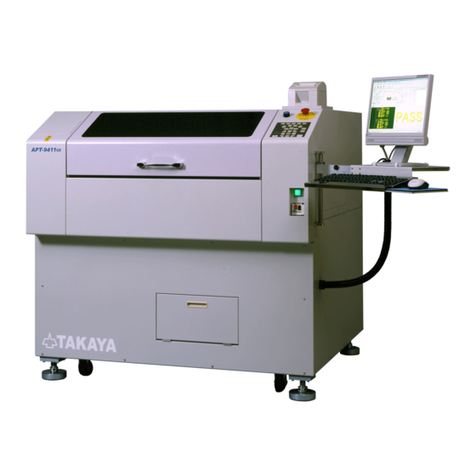
TAKAYA APT-9411 Series User manual

Vacuum unit
Vacuum unitVacuum unit
Vacuum unit
VC
VCVC
VC-
--
-9500
9500 9500
9500 Operator’s Guide
Operator’s GuideOperator’s Guide
Operator’s Guide
TAKAYA


- 1 -
Preface
The Vacuum unit VC-9500 is one of options designed for the Takaya Fixtureless tester APT-9411
Series and the sister models. If the VC-9500 is integrated into the tester, you may have etter pro ing
contact ecause it can more or less correct a warpage of the oards under test.
Please read this manual thoroughly efore using this option. Then keep this manual handy for
answers to any questions you may have.
If you have any questions or thoughts you would like to share with us – we would like to hear from you.
(NOTE)
1. The design of the product and software are under constant review and while every effort is made to
keep this manual up to date, we reserve the rights to change specifications and equipment at any
time without prior notice.
2. Windows®, Windows®NT is a registered trademark of Microsoft Corporation. Also the company
name and the product name listed in this User’s guide are the trademark of each company.
3. No portion of the contents of this pu lication may e reproduced or transmitted in any form or y
any means without the express written permission of TAKAYA CORP.

- 2 -
Introduction
Safety symbols
Symbol Explanation
Calls attention to a procedure, practice, or condition that could possi ly
cause serious accident or death.
Calls attention to a procedure, practice, or condition that could possi ly
cause odily injury or damage to the product.
Calls attention to a procedure, practice, or condition that could possi ly
damage to the product.
Calls attention to general instruction. Failing to follow this could loss of data
stored on disks causes possi ly misjudge the unit under test, or damage to
the product.
Calls attention to “One-point advice” which should e useful when you are at
a loss to operate the products.

- 3 -
Configuration
The VC-9500 is composed of following components.
No.1 No.2 No.3 No.4 No.5
No.6 No.7 No.8
[ Fig.1 ]
No.
Name Type Q’ty
Remarks
1 Vacuum pad unit 4 With air tu e
2 Manifold 1
3 Magnet ase 1
4 Ca le holder SA941-46616P0 4
5 Vacuum ejector unit 1
6 Air tu e Φ6, 2200mm 1
7 Air hose 5m 1
8 Filter regulator unit 1

- 4 -
[ Fig.2 ] Example of use
Manifold
Magnet ase
Air tu e
φ6 2200mm
Ca le holder
Manifold
Air tu e
Vacuum pad unit
Support pin

- 5 -
System Setting
When the VC-9500 is used for the first time, Option mode in the APT-9411 software requires initial
setup y users. This setting will e saved in Master.mdt file in the system directory.
In addition, the use of the VC-9500 is user-setta le every test program in Data mode.
Initial setup in Option mode
[Operating procedures]
1)
Click on the Menu ar to select “Option Mode”, and it displays Option Mode window.
[ Fig.3 ] Tool > Mode setting > Option Mode
[ Fig.4 ] Option Mode
2)
Click “Vacuum unit” on the left of the Option Mode window and select the ox “Use Vacuum Unit”.
Then click the OK utton to get the display ack to the Main window.
[ Fig.5 ]

- 6 -
Setup in ata mode
[Operating procedures]
1)
Click on the Menu ar to select “Data Mode”, and it displays Data Mode window. (Refer to Fig.6,7)
[ Fig.6 ] Tool > Mode setting > Data Mode
[ Fig.7 ] Data Mode
2)
Click “Restricted area” on the left of the Data Mode window and select the ox “Use Vacuum Unit”.
In addition, if you click “Vacuum” utton at the top right corner on the display, you can demonstrate
the operation check as many times as needed. Click the OK utton to get the display ack to the
Main window.

- 7 -
Precautions
The VC-9500 is activated (sticks to the UUT to pull it down) when the supporter goes up and releases
the UUT when the supporter goes down. Appearing elow is some precautions to know when the
VC-9500 is used on the tester.
1. To activate the VC-9500 correctly, it is a solutely necessary to provide air that fulfills the condition
elow.
Primary air pressure : 0.65MPa
Air consumption : 60NL min
2. Once the VC-9500 has een turned on, normally the UUT is pulled down a little lower than the
testing level. You should put a support pin closer to each vacuum pad to keep the UUT in a
horizontal position.
3. All Vacuum pad units must always stick to the UUT properly when the Vacuum ejector unit operates.
In case that any of Vacuum pad units is not used, make sure to close the valve on the manifold y
the handle.
[ Fig.9 ]
4. The ru er head diameter of the vacuum pad unit is 10Φ. So you should lay the vacuum pad unit
so that the ru er head touches the flat surface on the UUT where is wider than 10Φ. (Refer to
Fig.10, 11)
Support pin
Test level Lower than test level
Close
Open
Handle
Vacuum pad unit
Manifold
Close up
[ Fig.8 ]

- 8 -
Maintenance
This section descri es the procedures for replacing “Ru er pad” on the top of Vacuum pad unit and
for cleaning the vacuum filter used in the Vacuum ejector unit.
WARNING
Make sure that the tester is powered off and unplugged efore starting your operation.
Otherwise it could possi ly cause odily injury or mechanical trou le.
Rubber pad replacement
[Operating procedures]
1)
Use your Allen wrench to remove the ru er head y turning the inner fitting counterclockwise
while fastening the vacuum pad unit with a spanner. (Refer to Fig.10)
2)
Separate the inner fitting from the ru er head and replace the ru er pad with a new one.
(Refer to Fig.11)
3)
Install the ru er head again y the Allen wrench while fastening the vacuum pad unit with a
spanner. In this case, make sure not to put any foreign material inside the vacuum pad unit.
[ Fig.10 ] [ Fig.11 ]
Inner fitting
Allen wrench
Ru er head
Vacuum pad
Vacuum pad unit
Spanner Ru er pad (10Φ)
(PJG-10-U)

- 9 -
Filter cleaning
Make sure to check the filter inside the Vacuum ejector periodically to keep it as clean as possi le. If
the filter was plugged up (ex. flux, dust so on), it gives ill effect to the performance of the vacuum
ejector unit.
[Operating procedures]
1. Remove the rear cover and open the vacuum ejector cover. (Refer to Fig.12)
[ Fig.12 ]
2. Loosen the locking kno to remove the filter from the vacuum ejector unit. (Refer to Fig.13)
3. Use your air gun to clean the filter. (Refer to Fig.14)
(NOTE) When the filter was too dirty to clean, it is recommended to replace it with a new one.
In addition, make sure to handle the filter with care, ecause it is soft and easy to get
damages.
4. Put the filter ack in the vacuum ejector unit and fix it with the locking kno . (Refer to Fig.14)
[ Fig.13 ] [ Fig.14 ]
5. Close the vacuum ejector cover and put the rear cover on the tester.
(NOTE) Make sure not to put any foreign material inside the vacuum ejector unit while you are
cleaning it.
Rear cover
Vacuum ejector cover
Filter
Locking kno
tighten
loosen
Vacuum ejector unit
Filter
Air gun
Keep away!

- 10 -
Vacuum pad extension unit
Although the VC-9500 is equipped with four (4) Vacuum pad units as standard, you can increase up to
eight (8) Vacuum pad units as needed. This section descri es “Vacuum pad extension unit” as option
in case you need it.
Unit Contents
No, Name Type Q’ty
1 Manifold (*1)
2 Magnet ase
3 Air tu e φ6 300mm
4 Air tu e φ6 200mm
Extension
manifold
kit
5 Air connect KQU06-00
1
6 Vacuum pad unit Air tu e
7 Ca le holder
Vacuum pad
extension unit
Vacuum pad
8 Support pin SP-098
1-4
(*2)
No.1 No.2 No.3 No.4 No.5 No.6 No.7 No.8
(*1) The num er of the air joint (Air Open/close type) installed on the manifold depends on the Vacuum
pad unit to e added.
(*2) The num er of Vacuum pad extension unit is user’s option.

- 11 -
[Operating procedures]
Add the Vacuum pad extension unit on the tester as descri ed elow.
1)
Connect all components as illustrated in Fig.15.
[ Fig.15 ]
2)
Connect the Vacuum pad units to the manifold.
3)
Set the ca le holders on any proper position to hold the air tu e down.
4)
All that you need to do is completed.
Air connect (*2)
Magnet ase (*1)
Air tu e (*2)
φ
6 300mm
Magnet ase(*2)
Air tu e φ6 (*1)
Manifold (*2)
Vacuum pad unit (*2)
(*1) Standard unit
(*2)
Extension unit
Air tu e (*2)
φ6 200mm
Manifold (*1) Ca le holder (*2)

Table of contents
Introduction··································································································································2
Safety sym ols ·························································································································2
Configuration ·······························································································································3
System Setting ····························································································································5
Initial setup in Option mode ······································································································5
Setup in Data mode ··················································································································6
Precautions ·································································································································7
Maintenance································································································································8
Ru er pad replacement ··········································································································8
Filter cleaning ···························································································································9
Vacuum pad extension unit·······································································································10

APT-9411 Vacuum unit VC-9500 Operator’s guide
VOL.2
TAKAYA CORP.
Issued on: April, 2009
Made in Japan
Other manuals for APT-9411 Series
3
This manual suits for next models
1
Table of contents
Other TAKAYA Test Equipment manuals