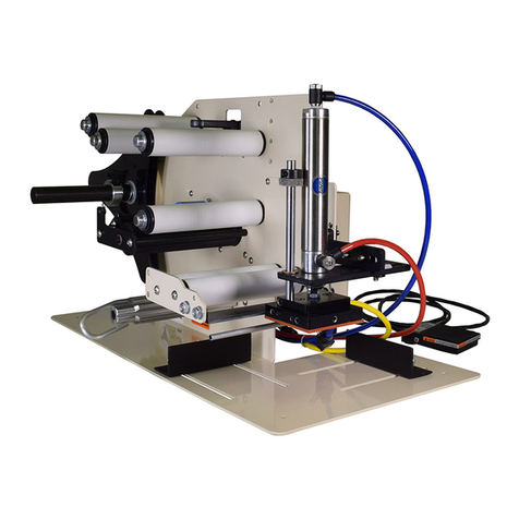
TAKE-A-LABEL TAL-3100C User manual

TAKE-A-LABEL, Inc.
Operation Manual
TAL-3100C
Tamp Applicator
TAKE-A-LABEL
16900 Power Dr.
Nunica, MI 49448
Phone (616) 837-9300
Fax (616) 837-9301
www.take-a-label.com
Email: sales@take-a-label.com

Page 2.1
TAL-3100C Tamp Applicator
Machine Startup:
1. Mount the TAL-3100C on an appropriate mounting stand. Be sure to mount the
labeler using only the mounting arms.
2. Plug the TAL-3100C directly into a 110 VAC 15-amp Grounded outlet.
Extension cords may result in improper labeler operation and are not recommend
by Take-A-Label, Inc.
3. Connect the labeler to a sufficient air supply. Note: air requirements are 60 PSI
clean dry air. Note: The TAL-3100C Typically operates between 30-50 PSI.
When air is connected the vacuum generator will continually release air to create
the vacuum effect.
Label Threading:
1. Remove outer unwind disc (61) and install new roll of labels and replace disc.
2. Pull label web under the first Idler Roller (25A), and through photo eye (18).
Continue pulling the web downward and thread between bottom of roller (25C) and
the top of the Peel Plate (1).
3. Pull the web back under the Peel Plate (1), pulling toward the rear of the machine.
4. Keep the liner under the last Idler roller (25B), pulling web up and wrapping over the
drive roller (39), and down between the drive roller (39) and pinch roller (22). Then
up to the waste wind shaft (52).
a. Note: The pinch roller (22) is spring loaded. Slight pressure will be needed to
separate the pinch roller from the drive roller for threading.
5. Install waste wind clip (3) on waste wind shaft (52) pinching the webbing between
the shaft and the clip.
Label Setup:
The label advance potentiometer resides on top of the TAL-3100C electrical housing.
The purpose is to adjust the stopping position of the label with respect to the peel plate.
With the label advance pot turned all the way counterclockwise the photo eye will stop
the applicator instantly when it senses a gap. By rotating the potentiometer toward the +
the applicator will dispense more of the label, and by rotating the potentiometer toward
the –the applicator will dispense less of the label.
1. To setup the label position, rotate the label advance pot to the –as far as it will rotate.
2. The goal is to have the applicator stop with a label gap right at the peel edge.
3. Activate the applicator and watch the dispensing label. If the label does not advance far
enough turn the label advance pot to the +, and repeat until one label is completely
dispensed and the next label is stopped at the peel edge.

Tamp Head Placement:
1. The tamp head placement is crucial for consistent label application.
2. The vertical gap between the peel plate and tamp pad should range from 0”-1/32”. If not
loosen the nut at the base of the tamp cylinder rod, and unthread to lower the tamp pad or
screw in the rod to raise the tamp pad height.
3. The horizontal gap between the peel plate and the tamp pad should range from 0”-1/32”.
If not loosen the horizontal mounting bolts and align to the acceptable range.

Air Assist Tube Placement:
1. The air assist tube is used to assist the label out onto the vacuum pad. As a rule of thumb,
the blast pattern from this tube should be directed at a 30° angle onto the vacuum pad.
This angle may vary due to several factors, as a result different blast angles may have to
be experimented with.

Teaching the photo eye:
1. It is recommended that you teach the photo eye (18) with every new roll of labels used.
2. Remove one label from the webbing and place the webbing only in the photo eye.
3. Press and hold the “Normal” button on photo eye for 3 seconds. When the lights finish
flashing the photo eye is taught.

Tamp Head Dwell Time –Label Advance Delay
Adjusting Dwell Time:
•Knob A: increases or decreases the time before the label is
advanced on to the tamp pad. This variance will occur after
activating the footswitch and beginning the cycle.
Adjusting Label Advance Delay
•Knob B: increases or decreases the amount of time the tamp pad
remains at the bottom of the cylinders stroke. Before returning to
the raised position.

Recommended Spare Parts
for the TAL-3100C
Qty.
Description
Part #
1
Pinch Roller
31002
1
Waist wind Clip
45131
2
Unwind Disc
45136
1
Motor
30031
1
Photo Cell Label Sensor
30106
2
Drive “V” Belt
31267
1
Circuit Board
31057
1
Unwind Felt Pad
72618
1
Main Fuse
45157
1
Peel Edge Cover
31375
2
Left Hand Torsion Spring
21027
2
Right Hand Torsion Spring
21028
Depending on frequency of use and importance of the machine function, this list
may need to be modified to include more of each part to prevent any down time.


Parts List
Part #
Description
#
11002
Peel Plate
1
11008
Unwind Shaft
2
45129
Waste Wind Clip
3
21004
Outboard Support Plate
4
21010
Pinch Roller Shaft
5
21012
3” Drive Shaft
6
21027
Torsion Spring LH
7
21028
Torsion Spring RH
8
25112
Unwind Washer
9
25113
Unwind Spring
10
26001
Unwind Collar
11
26002
Unwind Hub
12
30005
Pneumatic Cylinder
13
30024
Anti-Rotation Rod
14
30029
Tamp Pad Base Plate
15
30031
Motor; TAL 3100C/DC
16
30074
CTC 114 Shaft Collar 1/2"
17
30106
Tri-Tronics Label Eye
18
30124
Filter Regulator
19
30151
CTC Shaft Collar
20
30653
½-13 x 3/4” BHCS
21
31002
Pinch Roller
22
31003
Outboard Support Shaft
23
31004
Idler Roller Shaft
24
31006
Idler Roller (A, B, C)
25
31009
Pinch Roller Side Plate
26
31014
Connecting Bracket
27
31015
Plastic Bearing
28
31017
Long Bushing
29
31020
Cylinder Cross Mount Plate
30
31021
Cylinder Mount Plate
31
31029
Rewind Bushing
32
31053
T-Nut/ Bond/8020
33
31140
TAL-3100C/W Housing
34
31141
TAL-3100C/W Cover
35
31057
Control Board
36
31059
Label Advance
37
31060
Rewind Bracket
38
31102
Driver Roller
39

31142
Motor Spacer
40
31143
TAL-3100C/W Frame
41
31267
V Belt
42
31282
V Belt Tensioner
43
31373
V Belt Pully
44
31717
Air Assist Tube
45
31718
Air Assist Bracket
46
31722
Valve Assembly
47
31723
Flow Control Tube
48
31725
Vacuum Generator
49
31047
Extended Scanner Bracket
50
40007
On/Off Switch
51
72613
Waste Wind Shaft
52
45136
Unwind Disk
53
25212
Power Cord
54
72618
White Felt 4x4
55
81830
Shaft Caps
56
81912
Small Cord Grip
57
31144
TAL-3100C Threading Label
58
31146
TAL-3100C Name Label
59
31824
Shoulder Bolt 10-32
60
45136
Unwind Disk
61
25102
3/8” Black Plug
62
30208
Photo Eye Product Sensor
63
30084
Custom Tamp Pad
64

Table of contents
Other TAKE-A-LABEL Printer Accessories manuals