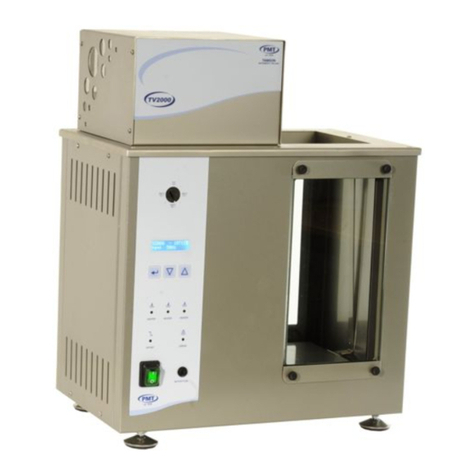
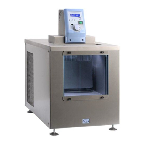
Tamson Instruments TC16 User manual

Van ’t Hoffstraat 12
2665 JL Bleiswijk, The Netherlands
T. 31 (0) 10 522 43 73
Tamson Instruments bv
Page 1/20
tc16-40-58-man.docx Rev. 2.4 UK 9-21
ISO 9001 : 2015
NL/PRO 238239125
VAT: NL 80 66 34 984 B01
Bank account no.:
NL28 INGB 0007 350 370
NL95 RABO 0160100046
Chamber of commerce 27 16 95 41
USER-
MANUAL
TC16-40-58

Van ’t Hoffstraat 12
2665 JL Bleiswijk, The Netherlands
T. 31 (0) 10 522 43 73
Tamson Instruments bv
Page 2/20
tc16-40-58-man.docx Rev. 2.4 UK 9-21
ISO 9001 : 2015
NL/PRO 238239125
VAT: NL 80 66 34 984 B01
Bank account no.:
NL28 INGB 0007 350 370
NL95 RABO 0160100046
Chamber of commerce 27 16 95 41
1SAFETY AND WARNINGS ......................................................................................................................3
2WARRANTY .............................................................................................................................................3
3PRECAUTIONS AND HAZARDS ............................................................................................................4
4INSTALLATION........................................................................................................................................4
4.1 IMPORTANT ..........................................................................................................................................................4
4.2 UNPACKING..........................................................................................................................................................4
4.3 INITIAL USE...........................................................................................................................................................5
4.4 FILLING THE BATH .................................................................................................................................................5
5CONNECTING..........................................................................................................................................7
6INTRODUCTION TO THE TC SERIES ....................................................................................................8
6.1 GENERAL.............................................................................................................................................................8
6.2 PUMP ..................................................................................................................................................................8
6.3 COOLING .............................................................................................................................................................8
6.4 OVER-TEMPERATURE SAFETY ................................................................................................................................9
6.5 ADJUSTING THE MECHANICAL OVER-TEMPERATURE PROTECTION THERMOSTAT ........................................................9
6.6 FLUID LEVEL ......................................................................................................................................................10
6.7 FLUID LEVEL DETECT..........................................................................................................................................10
7OPERATION...........................................................................................................................................11
7.1 SWITCHING ON ...................................................................................................................................................11
7.2 CONTROL PANEL ................................................................................................................................................11
7.3 BACKSIDE OF THE THERMOSTATIC BATH ................................................................................................................12
7.4 SELECTING PARAMETERS ....................................................................................................................................12
8QUICK START........................................................................................................................................14
8.1 TUNING THE BATH...............................................................................................................................................14
8.2 TUNE PID VALUES ..............................................................................................................................................15
8.3 DESELECT TUNING ..............................................................................................................................................15
8.4 MANUAL TUNING .................................................................................................................................................15
8.5 DRAINING BATH FLUID..........................................................................................................................................16
8.6 USING THE DRAIN TAP (OPTIONAL) ........................................................................................................................16
8.7 MAINTENANCE....................................................................................................................................................16
9TROUBLE SHOOTING...........................................................................................................................17
9.1 GENERAL...........................................................................................................................................................17
9.2 MESSAGE ON DISPLAY.........................................................................................................................................18
10 SPECIFICATION.................................................................................................................................18
10.1 TECHNICAL SPECIFICATIONS OVERVIEW.................................................................................................................18
11 SPARE PARTS...................................................................................................................................19
12 DISCLAIMER ......................................................................................................................................19
13 CE DECLARATION OF CONFORMITY.............................................................................................20

Van ’t Hoffstraat 12
2665 JL Bleiswijk, The Netherlands
T. 31 (0) 10 522 43 73
Tamson Instruments bv
Page 3/20
tc16-40-58-man.docx Rev. 2.4 UK 9-21
ISO 9001 : 2015
NL/PRO 238239125
VAT: NL 80 66 34 984 B01
Bank account no.:
NL28 INGB 0007 350 370
NL95 RABO 0160100046
Chamber of commerce 27 16 95 41
1 SAFETY AND WARNINGS
Make sure before installing or operating the equipment to read and understand all instructions and safety
precautions listed in this manual. If there are any questions concerning the operation of the equipment or
about the information given in this manual please contact your local dealer or our sales department first.
Performance of installation, operation, or maintenance other than those described in this manual may result
in a hazardous situation and may void the manufacturer's warranty.
Never operate equipment that is not correctly installed. Unqualified personnel must not operate the
equipment. Avoid damage to the equipment, or its accessories, caused by incorrect operation.
Important:
-When performing service, maintenance or moving the apparatus, always disconnect the apparatus
at the main's socket,
-Proper skilled and trained personnel are only allowed to operate this equipment,
-Take notice of warning labels and never remove them,
-Refer service and repairs to qualified technician,
-If a problem persists, call your supplier or Tamson Instruments bv.
2 WARRANTY
Tamson Instruments bv. warrants that all their manufactured equipment is free from defects in material and
workmanship, preventing the machine from normal operation. Tamson Instruments bv does not warranty that
the equipment is fit for any other use than stated in this manual. The manufacturer can only be held
responsible for the security, reliability and performance of the equipment, when operated in accordance with
the operating instructions, extensions, adjustments, changes and/or if repair is performed by Tamson
Instruments bv. or authorized persons only. This warranty is limited to one year from the date of invoicing. All
equipment and materials are subject to standard production tolerances and variations.

Van ’t Hoffstraat 12
2665 JL Bleiswijk, The Netherlands
T. 31 (0) 10 522 43 73
Tamson Instruments bv
Page 4/20
tc16-40-58-man.docx Rev. 2.4 UK 9-21
ISO 9001 : 2015
NL/PRO 238239125
VAT: NL 80 66 34 984 B01
Bank account no.:
NL28 INGB 0007 350 370
NL95 RABO 0160100046
Chamber of commerce 27 16 95 41
3 PRECAUTIONS AND HAZARDS
Before attempting to operate the bath read all parts
of this manual carefully to insure smooth operation
and avoid damage to the equipment or its
accessories.
If a malfunction occurs, consult section "Fout!
Verwijzingsbron niet gevonden.”, pageFout!
Bladwijzer niet gedefinieerd. at the end of this manual.
If problem persists, call your supplier or Tamson
Instruments bv. Never operate the equipment if not
correctly installed. The equipment must be operated only
by qualified personnel. Avoid damage to the equipment
or its accessories through incorrect operation.
Environment
Panel sealing
Confirms EN60529:
IP65
Environment Temperature
0 tot 35°C. Supply
enough ventilation
Humidity
5 tot 95 %, non
condensating
Atmosphere
Not suited for altitudes
above 2000m
or
explosive/corrosive
environment
Pollution cat. 2
Conducting pollution
must be prevented
4 INSTALLATION
4.1 Important
Tamson Instruments bv is not responsible for any
consequential damage or harm caused by using this
bath. Repairs on the electrical system of the bath may
only be carried out by well trained and authorized
persons.
4.2 Unpacking
Before leaving the factory Tamson baths are adequately
packed to prevent damage during normal transportation.
Check the packing for external damage and make a note
on the shipping documents if any damage is found.
Always retain the cartons and packing material until the
bath has been tested and found in good condition.
(Transport companies generally will not honor a claim for
READ
CAREFULLY
REMOVE ALL
PACKAGE MATERIAL

Van ’t Hoffstraat 12
2665 JL Bleiswijk, The Netherlands
T. 31 (0) 10 522 43 73
Tamson Instruments bv
Page 5/20
tc16-40-58-man.docx Rev. 2.4 UK 9-21
ISO 9001 : 2015
NL/PRO 238239125
VAT: NL 80 66 34 984 B01
Bank account no.:
NL28 INGB 0007 350 370
NL95 RABO 0160100046
Chamber of commerce 27 16 95 41
damage if the respective packing material is not available
for examination).
The shipment contains at least the bath as mentioned in
the delivery checklist. Further the consignment might
contain one or more viscometers, individually packed in
small boxes with the calibration certificate included in the
box, as well as ASTM thermometers, thermometer
holders etc. Please see the packing list for details
concerning total contents of consignment.
Before filling the bath remove any remaining packing
material from its interior. The interior of the bath can
be accessed by taking off the lid on the top of the
bath.
4.3 Initial use
Before filling the bath make sure that the bath is clean.
Place the bath spirit level, and connect it to the mains
after the mains switch is placed in “off” position. Use a
mains supply with proper grounding.
Important: Never use the bath without fluid
4.4 Filling the bath
The bath-fluid level must be 10- to 20 mm below the edge
of the top-plate.
In no case the fluid level may be lower than 60 mm under
the edge. This can cause severe damage to the heating
element.
10 - 20 mm
Max. 60 mm

Van ’t Hoffstraat 12
2665 JL Bleiswijk, The Netherlands
T. 31 (0) 10 522 43 73
Tamson Instruments bv
Page 6/20
tc16-40-58-man.docx Rev. 2.4 UK 9-21
ISO 9001 : 2015
NL/PRO 238239125
VAT: NL 80 66 34 984 B01
Bank account no.:
NL28 INGB 0007 350 370
NL95 RABO 0160100046
Chamber of commerce 27 16 95 41
For working temperatures above +80°C a fluid with a high
boiling point must be used. The bath fluid also has to be
chemically stable and must have low viscosity preventing
damage to the pump. Tamson oil type 150 has these
characteristics and is recommended to use for
temperature ranges which lie between +80°C and
+150°C.
Silicon oil can be used for temperatures between +20°C
and +150°C.
It is very important to select a liquid with a viscosity of less
than 20 mm²/s at the operating temperature and a flash
point which is well above the operating temperature.
When viscosity of the bath fluid is too high at room
temperature, the motor-fuse will be activated. In such a
case the bath fluid can first be heated to set point
temperature. When the bath has reached it’s set point the
motor fuse can be reset by pressing it. This way of
operating will reduce the life of the motor and is thus not
recommended.
Type
Remarks
Life
Viscosity [mm²/s] X
Temp.
Range
Package
Ordering
code
150°C
200°C
250°C
80°C
100°C
150°C
200°
C
Mineral
T150
Yellow
Mineral oil
1/2 yr
X
X
20
7
3
80..150°
C
20 ltrs
00T0220
Silicon
200 -10
Transparent
Dimethyl siloxane
polymer
No limit
200hrs
<10hrs
4
3.5
2.5
20..150°
C
20 ltrs
08T0001
Silicon
200 -50
Transparent
Dimethyl siloxane
polymer
No limit
200hrs
<10hrs
20
15
9
80..150°
C
20 ltrs
00T0226
Silicon
Silicon 210
Dark
Dimethyl poly
siloxane
No limit
<2yrs
<1yr
(35)
30
22
12
80..250°
C
20 ltrs
00T0231
Silicon
Silicon 550
Colorless
Polyphenyl methyl
dimethyl siloxane
No limit
<1yr
<1200
hrs
(50)
20
12
5
80..250°
C
20 ltrs
00T0238
FLASH POINT
> OPERATING
TEMPERATURE
VISCOSITY
< 20 mm²/s
PRESS
BUTTON TO
RESET MOTOR
FUSE

Van ’t Hoffstraat 12
2665 JL Bleiswijk, The Netherlands
T. 31 (0) 10 522 43 73
Tamson Instruments bv
Page 7/20
tc16-40-58-man.docx Rev. 2.4 UK 9-21
ISO 9001 : 2015
NL/PRO 238239125
VAT: NL 80 66 34 984 B01
Bank account no.:
NL28 INGB 0007 350 370
NL95 RABO 0160100046
Chamber of commerce 27 16 95 41
Do not use demineralized or distilled water. This
water can lead to corrosion of the bath and moving
parts. The corrosion can wear out the pump bearings
5 CONNECTING
Before plugging TC 16, TC40 or TC58 into the mains
socket, make sure the voltage of the bath corresponds to
the local voltage and frequency.
Use a mains supply that is well earthed, clean of
interference and suitable for the acquired electrical
load of the bath.

Van ’t Hoffstraat 12
2665 JL Bleiswijk, The Netherlands
T. 31 (0) 10 522 43 73
Tamson Instruments bv
Page 8/20
tc16-40-58-man.docx Rev. 2.4 UK 9-21
ISO 9001 : 2015
NL/PRO 238239125
VAT: NL 80 66 34 984 B01
Bank account no.:
NL28 INGB 0007 350 370
NL95 RABO 0160100046
Chamber of commerce 27 16 95 41
6 INTRODUCTION TO THE TC SERIES
The TAMSON model TC baths are used for precise
temperature control. This series offers a choice in
relatively large bath volumes.
6.1 General
The TAMSON baths are constructed throughout from
corrosion-resistant –stainless steel and brassTeflon –
materials. Outher casing is zinc plated powder coated
steel. The bath is effectively insulated against heat loss
by a layer of Armaflex® rubber between the inner tank
and outer casing.
6.2 Pump
A circulation pump is built-in to guarantee an uniform
temperature distribution within the bath and providing the
possibility to circulate through a closed external system.
The standard pump offers a motor protection (small
thermal fuse) which is placed on the back panel of the
motor compartment. This protects the motor from
excessive loads.
When pumping viscous liquids the thermal fuse can
be activated. The motor fuse can be reset by pressing
the button.
The inlet and outlet of the pump are fitted with 8 mm hose
connections and 1/4” threaded fittings for metal tubing.
The outlet is provided with a small disc, stopping the
circulation action.
Before the fluid can begin circulating through
external systems this disc must be removed by
unscrewing the fitting and hose connection
removing the disc.
6.3 Cooling
The TC-bath is equiped with a cooling coil. Circulation of
fluid, with a lower temperature than the bath fluid, through
this coil will cool down the bath temperature. To get stable
control of the bath when using the cooling coil, the
temperature of the cooling fluid has to be approximately
5°C lower than the set point temperature of the bath.
Cooling is need for set point temperatures of
approximately 42°C and lower.
REMOVE DISK
WHEN
CIRCULATING
PRESS
BUTTON TO
RESET MOTOR
FUSE

Van ’t Hoffstraat 12
2665 JL Bleiswijk, The Netherlands
T. 31 (0) 10 522 43 73
Tamson Instruments bv
Page 9/20
tc16-40-58-man.docx Rev. 2.4 UK 9-21
ISO 9001 : 2015
NL/PRO 238239125
VAT: NL 80 66 34 984 B01
Bank account no.:
NL28 INGB 0007 350 370
NL95 RABO 0160100046
Chamber of commerce 27 16 95 41
The cause for this relatively high temperature is the self
heating of the bath due to friction-heat of the pump. The
insulation of the bath prevents this energy to be
transferred into the environment. This causes a raise of
temperature in the bath up to 25 .. 30°C depending on the
environmental temperature and used bath fluid.
For cooling the bath down to lower temperatures, tap-
water is mostly used. Also a small circulator can be
connected to the cooling coil like the Tamson TLC10-3,
or TLC15.
6.4 Over-temperature safety
In case of electronic failure the possibility exists that the
heater element is continuously switched on. This will
cause extreme temperature raise. To prevent high
temperatures the bath is fitted with a mechanical
temperature switch (thermostat). This thermostat will
switch-off the bath at a preset temperature in the range
from 50 tot 270°C.
We advise to adjust the mechanical over temperature to
approximately + 25 C above the bath set point.
This safety construction prevents for example oil to be
heated above flash point which definetly will cause fire or
prevent evaporation of bath fluid due to high
temperatures.
The thermostat will automatically reset when the bath
temperature drops approximately 10°C below the pre-set
temperature. To continue normal operation the bath has
to be switched-off and on again.
6.5 Adjusting The Mechanical Over-
Temperature Protection Thermostat
•Turn the over-temperature protection (8, drawing
2) to its maximum (turn clockwise towards 50°C),
•Heat the bath to its set point,
•Gently turn the over-temperature protection anti-
clockwise, until the over-temperature protection is
activated, and system switches-off,
•Turn the over-temperature protection
approximately 25°C higher (turn clockwise),
Switch the bath off and on again. The bath is ready to
operate safely.

Van ’t Hoffstraat 12
2665 JL Bleiswijk, The Netherlands
T. 31 (0) 10 522 43 73
Tamson Instruments bv
Page 10/20
tc16-40-58-man.docx Rev. 2.4 UK 9-21
ISO 9001 : 2015
NL/PRO 238239125
VAT: NL 80 66 34 984 B01
Bank account no.:
NL28 INGB 0007 350 370
NL95 RABO 0160100046
Chamber of commerce 27 16 95 41
6.6 Fluid Level
Do not operate the bath with low fluid level.
When the fluid level is too low, bath fluid will vaporize
leading to toxic and flammable fumes.
Flammable fumes can lead to fire
Flammable fumes can be ignited by the not submersed
part of the heating element.
The level indicator(optional) will start to blink (white light)
when the fluid level is too low.
When the bath has been installed it must be filled
with an appropriate liquid. When working with water
the bath should be filled to 1 cm below the lid. For oil
the bath should be filled to not more than 5 cm below
the lid. Depending on the operating temperature the
liquid level in the bath should be observed and
excessive fluid should be removed.
The liquid level should be maintained between 1 and 3
cm below the lid during normal operation.
The heating element will be damaged when not fully
submerged in the bath fluid. A lower level than 5 cm
below the lid may damage the heaters. A high bath level
can cause overflow and might also damage the bath
insulation.
Low fluid level
- Can cause fire when heater gets partially
exposed
- Will damage the heater
6.7 Fluid Level Detect
Level detection is available as an option. When the fluid
level becomes too low an audible alarm is triggered.

Van ’t Hoffstraat 12
2665 JL Bleiswijk, The Netherlands
T. 31 (0) 10 522 43 73
Tamson Instruments bv
Page 11/20
tc16-40-58-man.docx Rev. 2.4 UK 9-21
ISO 9001 : 2015
NL/PRO 238239125
VAT: NL 80 66 34 984 B01
Bank account no.:
NL28 INGB 0007 350 370
NL95 RABO 0160100046
Chamber of commerce 27 16 95 41
7 OPERATION
7.1 Switching on
If the bath has been properly filled with fluid it can be
switched with the mains switch located on the front panel.
Choose a working temperature (set point).
7.2 Control Panel
1. LED Display
2. LED Over-temperature*
3. LED Heater
4. Up - key
5. Down –key
6. Page –key
7. Scroll - key
8. Safety thermostat
9. Mains On/Off
10. Top lid
* When the overtemperature safety is activated
wait until the bath temperature is lowered several
degrees. The safety thermostat will reset itself. Turn the
bath off and on again. The bath will continue operation.
SWITCH ON
9
8
10
1
2
3
4
7
5
6
8
9

Van ’t Hoffstraat 12
2665 JL Bleiswijk, The Netherlands
T. 31 (0) 10 522 43 73
Tamson Instruments bv
Page 12/20
tc16-40-58-man.docx Rev. 2.4 UK 9-21
ISO 9001 : 2015
NL/PRO 238239125
VAT: NL 80 66 34 984 B01
Bank account no.:
NL28 INGB 0007 350 370
NL95 RABO 0160100046
Chamber of commerce 27 16 95 41
7.3 Backside of the thermostatic bath
1 Cooling fan
2 RS 232 Communication
3 In and outlet pump
side view connection:
4 Mains cable
5 Motor fuse
6 Cooling coil, 1/4" outher thread
7 Switch for fan (only for TC16 with p/n 31T0671/
31T0861)
8 Fan (only for TC16 with p/n 31T0671/31T0861)
7.4 Selecting parameters
The front panel layout shows the following four operating
keys:
Press shortly and following is displayed
SP.1 - Temperature set point in °C,
tU.n - Tuning the bath (“Atune”),
Pb - Changing the tuning (PID) parameters "P"value
ti - Changing the tuning (PID) parameters "I"value
td - Changing the tuning (PID) parameters "D"value
OFSt - Change temperature readout offset (± 5°C)
Each time is pressed another option is displayed.
Up and Down keys allow changing the listed value. All
changed values, like set point and PID parameters, will
be kept in memory when pressing the page key to leave
2
1
3
7
4
6
5
8
PAGE
DOWN
UP
LIST

Van ’t Hoffstraat 12
2665 JL Bleiswijk, The Netherlands
T. 31 (0) 10 522 43 73
Tamson Instruments bv
Page 13/20
tc16-40-58-man.docx Rev. 2.4 UK 9-21
ISO 9001 : 2015
NL/PRO 238239125
VAT: NL 80 66 34 984 B01
Bank account no.:
NL28 INGB 0007 350 370
NL95 RABO 0160100046
Chamber of commerce 27 16 95 41
the menu. After switching off the power supply, changed
values are kept in memory.
SP.1
Set point adjust.
Press page key to confirm setting when altered.
tU.n
Auto tuning PID parameters, set on or off.
Off is default value here.
On, when selecting parameter 2nd time.
On.A is played. This indicates adaptive tune. Bath is adapting
PID setting in background operation. When in On.A mode.
PID values can not be set manually anymore.
pb
Changing the tuning (PID) parameters. 'Proportional band
value. Default value is 1, range 1 .. 100. (Proportional band
equals 1/proportional value).
Press page key to confirm setting when altered.
ti
Changing the tuning (PID) parameters 'Integrator' value.
Default value is 200. Range 1 .. 1200.
Press page key to confirm setting when altered.
td
Changing the tuning (PID) parameters 'Differentiator' value.
Default value is 0. Range 1 .. 600.
Press page key to confirm setting when altered.
OFST
Set offset. The offset value is added to the displayed bath
temperature. I.e. when the displayed bath temperature is
20.0°C, an offset of 0.2 displays a value of 20.2°C. An offset
of -0.2°C will display 19.8°C. Range is -5°C .. +5°C.
Press page key to confirm setting when altered.
Note
When tune is set to on, PID values can not be set. Change
tune to off en alter PID values.
Press page key to confirm setting when altered.

Van ’t Hoffstraat 12
2665 JL Bleiswijk, The Netherlands
T. 31 (0) 10 522 43 73
Tamson Instruments bv
Page 14/20
tc16-40-58-man.docx Rev. 2.4 UK 9-21
ISO 9001 : 2015
NL/PRO 238239125
VAT: NL 80 66 34 984 B01
Bank account no.:
NL28 INGB 0007 350 370
NL95 RABO 0160100046
Chamber of commerce 27 16 95 41
8 QUICK START
To quickly start operating the bath:
•Fill the bath with sufficient and appropriate fluid.
see filling the bath.
•Place the power plug,
•Switch on the bath using the mains switch,
•Choose a working temperature (set point):
Press once. Display will indicate "SP.1". Alter set point
temperature by using up and down key to select
the desired bath temperature.
Confirm by pressing .
8.1 Tuning the bath
The temperature control of the bath is based on a digital
PID system. When using different fluids in the bath each
with their own heat capacity, the use of external cooling
and external connected processes (circulation), or
working at different set point temperatures requires new
settings of the PID parameters. These parameters have
to be optimized after changes to the system when optimal
and accurate temperature control of the bath liquid is
required.
Tuning of the bath results in:
•Stable temperature control of the bath,
•No over- or undershoot of the temperature set
point,
•Quick response to deviations from the set point
caused by external disturbances.
Tuning can be done automatically or manually. The
parameters mentioned in table 1 will influence the control
of the bath.
Parameter
Description
Display
Proportional band
The bandwidth in display-units over which the output power is
proportional between minimum and maximum
Pb
Integration time
Determines the time taken by the controller to remove steady state error
signals
Ti
Derivative time
Determines the time taken by the controller to react on error signals.
Td
Table 1 Parameters influencing the temperature control
IN-TUNE

Van ’t Hoffstraat 12
2665 JL Bleiswijk, The Netherlands
T. 31 (0) 10 522 43 73
Tamson Instruments bv
Page 15/20
tc16-40-58-man.docx Rev. 2.4 UK 9-21
ISO 9001 : 2015
NL/PRO 238239125
VAT: NL 80 66 34 984 B01
Bank account no.:
NL28 INGB 0007 350 370
NL95 RABO 0160100046
Chamber of commerce 27 16 95 41
8.2 Tune PID values
Choose desired set point,
Wait until the bath has reached the set point temperature,
Highest temperature accuracy can be achieved when
tuning the bath. Select tU.n by pressing twice.
Press to choose “ON”,
Press 5 times to return to displayed PV
(PID values can no longer be adjusted unless the "tU.n"
value is set to off)
8.3 Deselect tuning
•Pressing twice,
•Display shows ”tU.n”,
•Press to choose “Off”,
•Press 5 times to return to displayed PV.
8.4 Manual tuning
The parameters for the PID control can also be changed
manually. The method described below provides fast
finding of the PID settings and is refereed to as the
method of "Ziegler Nichols"
This procedure is only to be followed when automatic
tuning is not functioning.
This method provides fast manual findings of the PID
values. Start the bath at its required running temperature:
1. Set the integral time “Ti” and the derivative Time
“Td” to off
2. Check if the Lcb and Hcb are set to auto
3. Ignore the fact that the temperature may not
settle precisely at the set point
4. If the temperature is stable, reduce the
proportional band Pb so that the temperature just
starts to oscillate. If the temperature is already
oscillating, increase the proportional band until it
begins oscillating. Allow enough time between
each adjustment for the loop to stabilize. Make a
note of the proportional band value “B” and the
period of oscillation “T” Set the Pb, Ti and Td
parameter values according to the calculations
given in the table below
Type of control
Proportional band
Integral time "ti"
Derivative Time "td"
Proportional only
2xB
Off
Off
P + I control
2,2xB
0,8xT
Off
P + I + D control
1,7xB
0,5xT
0,12xT

Van ’t Hoffstraat 12
2665 JL Bleiswijk, The Netherlands
T. 31 (0) 10 522 43 73
Tamson Instruments bv
Page 16/20
tc16-40-58-man.docx Rev. 2.4 UK 9-21
ISO 9001 : 2015
NL/PRO 238239125
VAT: NL 80 66 34 984 B01
Bank account no.:
NL28 INGB 0007 350 370
NL95 RABO 0160100046
Chamber of commerce 27 16 95 41
8.5 Draining bath fluid
Before removing flammable bath liquids take the
appropriate fire hazard precautions against these liquids.
When draining the bath fluid, be sure that the bath fluid
has cooled down to ambient temperature. If viscosity is
too high at ambient temperature to remove the fluid,
make sure that the hose to drain and waste container
can withstand the temperature of the bath fluid.
When removing bath fluid do not inhale toxic vapor.
Always use appropriate ventilation.
8.6 Using the drain tap (optional)
The TC baths can be drained via the drain tap located at
the backside of the apparatus.
The drain has an inner diameter of 3/8” gas fitting. The
drain can be connected onto a pipe, tube or drainage
system.
For safety reasons the tap can only be opened by using
a screwdriver. The thread inside the tap is 3/8".
8.7 Maintenance
Keep the apparatus free from dust. Regularly check the
cooling openings and remove dust with vacuum cleaner.
If necessary remove cover and clean internally. Use
appropriate protection when cleaning, dust can be very
unhealthy.

Van ’t Hoffstraat 12
2665 JL Bleiswijk, The Netherlands
T. 31 (0) 10 522 43 73
Tamson Instruments bv
Page 17/20
tc16-40-58-man.docx Rev. 2.4 UK 9-21
ISO 9001 : 2015
NL/PRO 238239125
VAT: NL 80 66 34 984 B01
Bank account no.:
NL28 INGB 0007 350 370
NL95 RABO 0160100046
Chamber of commerce 27 16 95 41
9 TROUBLE SHOOTING
All Tamson products are well designed and carefully
tested before shipping. This will not fully prevent small
problems in the field. Following will help you to locate
commonly known problems and how to fix them. In case
of doubt please check your local dealer or Tamson
Instruments bv.
9.1 General
Bath malfunction
The motor is not running and electronics is dead
Check mains fuse
Motor is not running:
Probably the motor fuse is activated. Restart the
motor by pressing the motor fuse .
Check viscosity of the bath fluid. High viscosity will
activate the motor fuse.
Electrical defect. Motor capacitor defective.
Replace capacitor or contact local dealer or
Tamson Instruments bv.
Problems with set point
Heater LED is not burning, motor is turning and
temperature raises above set point:
Setpoint too near to room temperature. Cooling of
the bath is needed.
Temperature doesn’t reach set point, motor turns
fast:
Bath fluid evaporates too quick. Use other fluid.
Heater malfunctions:
Measure electric mains current. Current below 2
amps indicate a problem with the heating element.
Temperature not stable
Tune the bath at the set point temperature.
Difference between ambient and bath temperature
is too small (Applied power indication is below
8%). Use cooling coil
PID values
Unable to set PID values:
Check if ATUN has been set to on. PID values can
no longer be adjusted unless the ATUN value is
set to off. See 8.4 selecting parameters.
Readout / indicator
The temperature readout on the display does not
correspond to the temperature measured.
Check the PT100 sensor
Level indicator on frontpanel blinks.
Fluid level probably too low, check fluid level
Be aware that the fluid level always needs to be
higher than the heating element(s).
An heating element which partially operates above
the fluid (so partially exposed to air above the fluid
level) can get hot en may possibly ignite the fbath
fluid.

Van ’t Hoffstraat 12
2665 JL Bleiswijk, The Netherlands
T. 31 (0) 10 522 43 73
Tamson Instruments bv
Page 18/20
tc16-40-58-man.docx Rev. 2.4 UK 9-21
ISO 9001 : 2015
NL/PRO 238239125
VAT: NL 80 66 34 984 B01
Bank account no.:
NL28 INGB 0007 350 370
NL95 RABO 0160100046
Chamber of commerce 27 16 95 41
9.2 Message on display
Code
What does it mean
What action to take
E61
Defect / calibration PT100
Check wiring and element. Ohmic value
at 0C=100R and at 100C=138R.
Replace PT100
E70
Error on operational parameters
E50
EEprom error
Auto - reset after 2 s
E82
Error on input during calibration
E4
EEprom error
Auto - reset after 2 s
E5
EEprom error
Auto - reset after 2 s
E6
Watchdog error
Auto - reset after 2 s
10 SPECIFICATION
10.1 Technical specifications overview
Item
Unit
TC16
TC40
TC58
Ordering
code
230V
50 or
60Hz
00T0671
00T0681
00T0691
115V
50 or
60Hz
00T0861
00T0851
00T0881
Power
[Watt]
1500
2900
2900
Materials
Used inside bath: stainless steel 304, brass
Range
Ambient .. 250C/..482F
Reading
Standard C, F on request
Setting ±
[°]
0.1
Stability ±
[°K]
0.02
0.02
0.02
Heating
[W]
1400**
2800
2800
Bath
volume
[L]
16
40
58
Pump
[mBar]
Max pressure 300*
Pump
[L/min]
Max flow 7.5*
Opening
[mm]
180 *210
420 *275
420 *275
Depth
bath
[mm]
220
200
300
Length
[mm]
455
705
705
Width
[mm]
295
375
375
Height
[mm]
440
440
590
Weight
[Kg]
21
30
35
CE
Conforms to CE regulation
* Optional pump with pressure max 1bar, flow max
16ltrs/min, reference: 24T0392. See specification sheet
"pumpgraph
** Additional heater 1400W optional to heat larger loads
when circualting

Van ’t Hoffstraat 12
2665 JL Bleiswijk, The Netherlands
T. 31 (0) 10 522 43 73
Tamson Instruments bv
Page 19/20
tc16-40-58-man.docx Rev. 2.4 UK 9-21
ISO 9001 : 2015
NL/PRO 238239125
VAT: NL 80 66 34 984 B01
Bank account no.:
NL28 INGB 0007 350 370
NL95 RABO 0160100046
Chamber of commerce 27 16 95 41
11 SPARE PARTS
12 DISCLAIMER
Information given herein is offered in good faith as
accurate, but without guarantee. Conditions of use and
suitability of the product for particular uses are beyond
our control; all risks of use of the product
are therefore assumed by the user.
We expressly disclaim all warranties of every kind
and nature, including warranties of merchantability
and fitness for a particular purpose in respect to the
use or suitability of the product.
Nothing is intended as a recommendation for uses which
infringe valid patents or as extending license under valid
patents. Appropriate warnings and safe handling
procedures should be provided to handlers and users.
Alteration of this document is strictly prohibited. Except to
the extent required by law, republication or
retransmission of this document, in whole or in part, is not
permitted. Tamson Instruments bv assume no
responsibility for accuracy of information unless the
document is the most current available. Tamson
Instruments neither represent nor warrant that the format,
content or product formulas contained in this document
comply with the laws of any other country except the
Netherlands.
Tamson Instruments bv, All rights reserved
Ordering number
Description
230V 50/60Hz
115V 50/60Hz
25T1242
25T1242
Fan 60x60 12V
04T0035
04T0045
Pump complete
25T1290
25T1308
Pump motor
24T8080
24T8083
Motor fuse
24T3300
24T3312
Motor Capacitor
06T0496
06T0497
PCB TE series
25T0194
25T0195
Heater 1400 Watts
25T194
25T0195
Boost Heater 1400 Watts
24T8541
Mains switch
28T4106
Keypad foil
28T4107
Front sticker TC16
28T4108
Front sticker TC40
28T4109
Front sticker TC58
24T8581
Safety thermostat
28T3022
Controller PCB 115V & 230V (Not programmed, when
ordering always specify bath (i.e. TC16, TC40, TC58)

Van ’t Hoffstraat 12
2665 JL Bleiswijk, The Netherlands
T. 31 (0) 10 522 43 73
Tamson Instruments bv
Page 20/20
tc16-40-58-man.docx Rev. 2.4 UK 9-21
ISO 9001 : 2015
NL/PRO 238239125
VAT: NL 80 66 34 984 B01
Bank account no.:
NL28 INGB 0007 350 370
NL95 RABO 0160100046
Chamber of commerce 27 16 95 41
13 CE DECLARATION OF CONFORMITY
Following equipment is in complience with EMC Directive 2014/30/EU:
Product: Thermostatic bath and circulator
Model: TC16 / TC40 / TC58
Serial code: Effective from 07Txxx
Manufacturer: Tamson Instruments bv
van 't Hoffstraat 12
2665 JL Bleiswijk
The Netherlands
The products are in conformity with the following specifications:
Item
Reference
Description
Test result
a
RoHS Directive
2011/65EU
p
b
EN 61010-2-010
Safety requirements for electrical
equipment for measurement, control,
and laboratory use. Particular require-
ments for laboratory equipment for the
heating of material
c
Machine Directive
2006/42/EC
Machinery Directive, of the European
Parliament and of the Council of 17 May
2006/42/EC 2nd Edition June 2010
p
d
EN 60204
Machinery Directive and Safety
requirements
p, pi
e
EN60950-1
Low Voltage Directive
p
f
EN61000-3-2
Harmonics
p
g
EN61000-3-3
Flicker
p3
h
EN61000-4-2 +A1+A2
ESD
p
i
EN61000-4-3 +A1+A2
Radiated immunity
p (anechoic room)
j
EN61000-4-4
Electrical Fast Transients
Minimum requirements pass
k
EN61000-4-5+A1
Surges
Minimum requirements pass
l
EN61000-4-6+A1
Conducted immunity
p
m
EN61000-4-11 +A1
Voltage dips and Voltage variations
p
n
EN55016-2-1
Conducted emission
p
o
EN55016-2-3
Radiated emission
p (anechoic room)
p = Pass
pi= Individually tested
p3 = Pass, condition of operating during Pst measurement: Operational with heating element 1400W.
Pst and Plt are not evaluated in accordance with A.5 of Annex A of EN 61000-3-3(1995) + A1(2001).
not applicable were:
Conducted discontinuous emissions (Clicks)
Radiated emission (OATS)
Magnetic field immunity
Entity responsible for marking this declaration :
Manufacturer, Tamson Instruments bv, van 't Hoffstraat 12, Bleiswijk The Netherlands,
Name : R.C. van Hall
Function : Director
Date : Sept 18, 2017
Version : 1.03
This manual suits for next models
8
Table of contents
Other Tamson Instruments Laboratory Equipment manuals