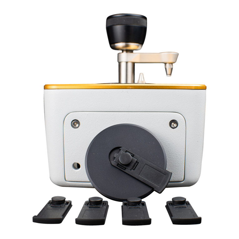
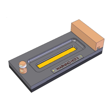
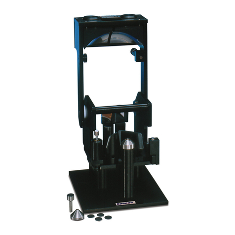
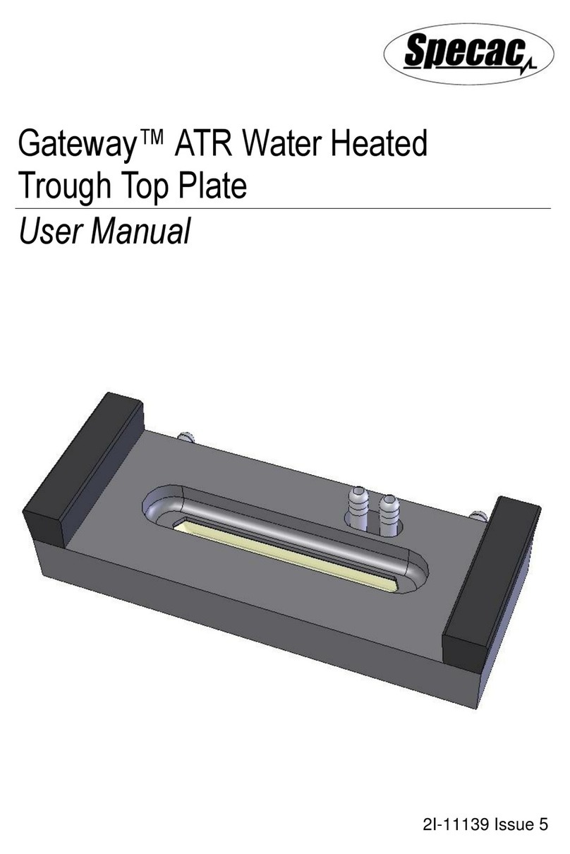
In fitting of either top plate assembly into position over the location pins
(16), the pressure plate and pad assembly (9) of the clamp assembly
(1) must be lifted up and away to allow for the clearance in fit. When
the trough top plate assembly (3) is fitted, the clamp assembly (1) for
any sample force contact is normally not needed for any liquid
sampling so can be kept raised. If the flat top plate assembly (4) is
being used, once it has been fitted correctly and after any solid sample
type has been placed over and to cover the entire ATR crystal surface
area, the clamping mechanism is employed to force the sample into
suitable contact for an ATR spectral measurement to be made.
Trough (3) and Flat (4) Gateway ATR Top Plates
The trough (3) and flat (4) top plate assemblies provided with the
Gateway™ ATR Accessory have ZnSe ATR crystals (17) (P/N
GS11145) supplied in place for use. There are further crystal options of
Ge (P/N GS11147) and Si (P/N GS11146) available for use in both
trough (3) and flat (4) top plate assemblies. The crystals (17) have
been sealed into position by epoxy resin gluing for any flat (4) top plate
assembly, but in any trough (3) or flow through top plate assembly
the crystal (17) type options are removable. They are sealed for
sample containment over the ATR crystal (17) surface within these top
plate assemblies from use of specific gaskets made of Isolast or Kalrez
material.
The Trough Top Plate Assembly
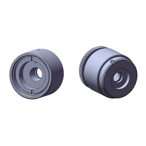
The ATR crystal (17) in the trough (3) top plate assembly is held in
place within the surrounding plate metalwork (18) from a pressure bar
(19) that pushes against the underside of the crystal (17) via a lead
pad (20) and seals the crystals (17) top surface against an Isolast
gasket (21). A central M4 x 5mm grub screw (22) within a base support
plate (23) is tightened to provide the force to the pressure bar (19) for
sealing of the whole assembly of parts. The base support plate (23) is
held in place by four M3 x 12mm cap head screws (24). This design for
a trough (3) top plate assembly allows for removal of the crystal (17)
for cleaning or for a change of crystal (17) completely if damage has
been sustained or for use of an optional ATR crystal (17) material.
(See Fig 7. –Underside View.).


