Tamson Instruments TV12LT User manual

van 't Hoffstraat 12
2665 JL Bleiswijk, THE NETHERLANDS
T. 31 (0) 10 522 43 73
tv12ltman Rev. 3.01 UK 0821
Tamson Instruments bv
Page 1/30
ISO 9001 : 2015
NL/PRO 238239125
VAT: NL 80 66 34 984 B01
Bank account no.:
NL28 INGB 0007 350 370
NL95 RABO 0160100046
Chamber of commerce 27 16 95 41
USER-
MANUAL
TV12LT

van 't Hoffstraat 12
2665 JL Bleiswijk, THE NETHERLANDS
T. 31 (0) 10 522 43 73
tv12ltman Rev. 3.01 UK 0821
Tamson Instruments bv
Page 2/30
ISO 9001 : 2015
NL/PRO 238239125
VAT: NL 80 66 34 984 B01
Bank account no.:
NL28 INGB 0007 350 370
NL95 RABO 0160100046
Chamber of commerce 27 16 95 41
1SAFETY AND WARNINGS ......................................................................................................................3
2WARRANTY .............................................................................................................................................3
3PRECAUTIONS AND HAZARDS ............................................................................................................4
4INSTALLATION........................................................................................................................................5
4.1 IMPORTANT ..........................................................................................................................................................5
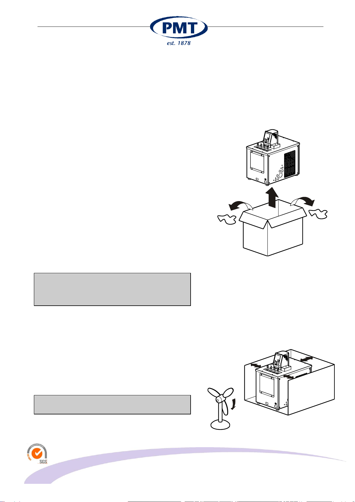
4.2 UNPACKING..........................................................................................................................................................5
2.1 TILTING................................................................................................................................................................5
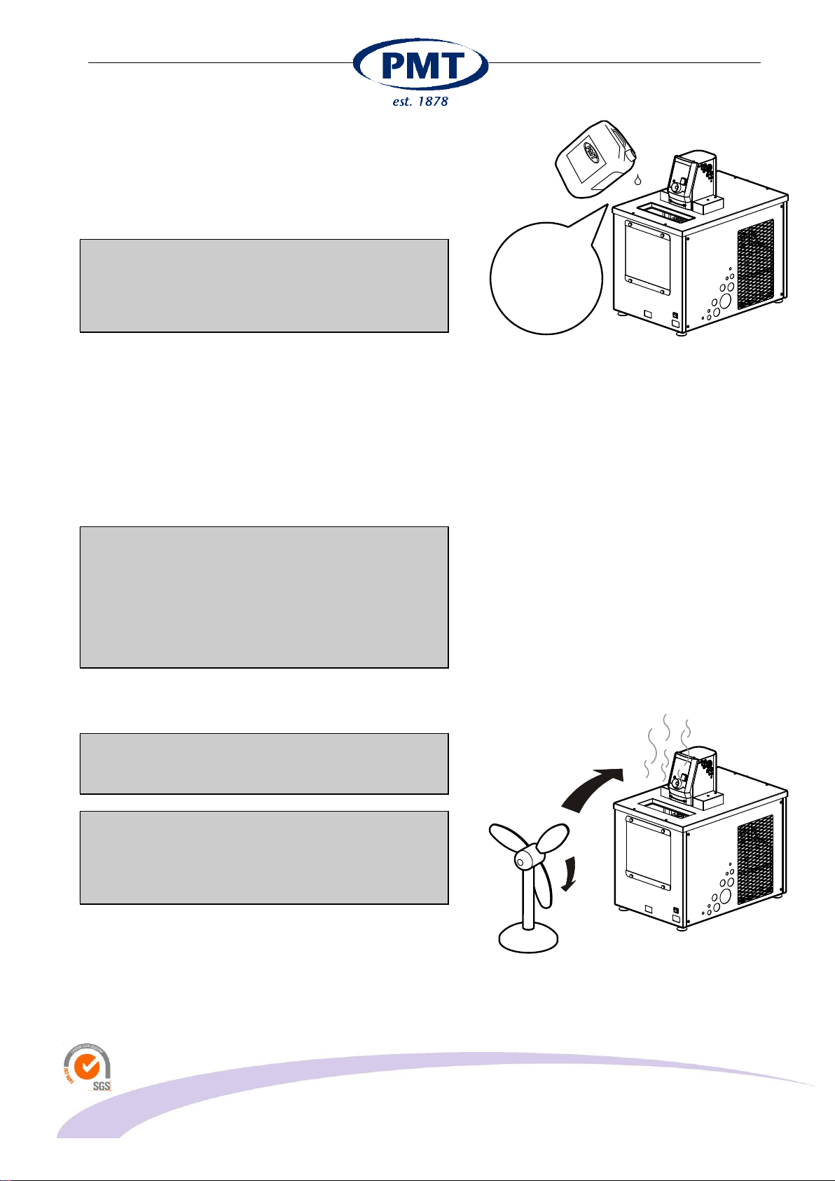
2.2 VENTILATION........................................................................................................................................................5
3BATH LIQUID...........................................................................................................................................6
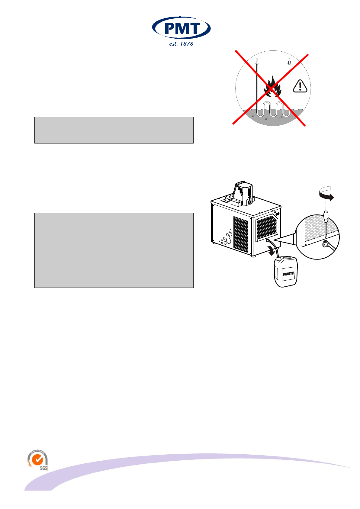
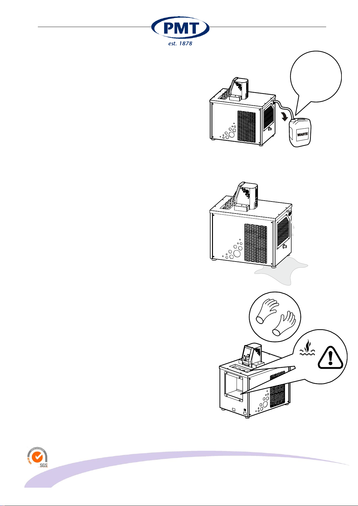
3.1 DRAIN BATH FLUID ................................................................................................................................................7
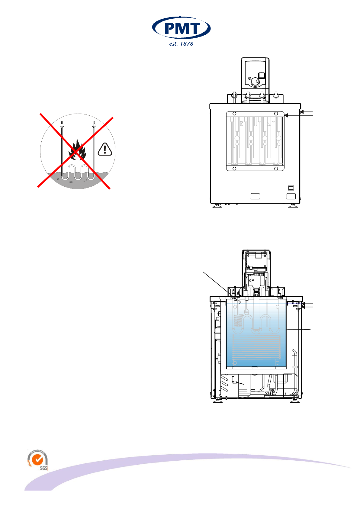
3.2 BATH FLUID LEVEL.................................................................................................................................................8
3.3 SAFETY AND PROTECTION......................................................................................................................................9
3.4 COOLING ...........................................................................................................................................................10
3.5 CONNECTING .....................................................................................................................................................11
4INTRODUCTION.....................................................................................................................................12
4.1 GENERAL...........................................................................................................................................................12
4.2 CONSTRUCTION..................................................................................................................................................12
4.3 STIRRER............................................................................................................................................................12
4.4 TEMPERATURE CONTROL AND SETTING .................................................................................................................12
4.5 FRONT PANEL ....................................................................................................................................................13
4.6 OVERVIEW MENU ITEMS.......................................................................................................................................13
5SAFETY SYSTEMS................................................................................................................................15
5.1 MECHANICAL OVER-TEMPERATURE PROTECTION....................................................................................................15
5.2 LEVEL PROTECT..................................................................................................................................................15
6OPERATING THE SYSTEM...................................................................................................................16
6.1 QUICK START.....................................................................................................................................................16
6.2 MENU ITEMS ......................................................................................................................................................16
7MANUAL TUNING..................................................................................................................................20
8MAINTENANCE......................................................................................................................................21
9TROUBLE SHOOTING...........................................................................................................................22
9.1 APPLICATION ERRORS .........................................................................................................................................22
9.2 BATH MALFUNCTION............................................................................................................................................22
9.3 PROBLEMS WITH SET POINT .................................................................................................................................22
9.4 FAULTY TEMPERATURE READING OR TEMPERATURE OFFSET ....................................................................................22
9.5 BATH TEMPERATURE DOES NOT BECOME STABLE ...................................................................................................23
9.6 BATH DOESN'T REACH SP....................................................................................................................................23
9.7 BLUE LED BLINKS ON FRONT PANEL .....................................................................................................................23
9.1 OVER-TEMPERATURE SAFETY THERMOSTAT...........................................................................................................24
10 SPECIFICATIONS ..............................................................................................................................25
10.1 PRECISION OF CONTROL......................................................................................................................................25
10.2 COOLDOWN .......................................................................................................................................................25
10.3 SETTLING TIME BATH FLUID ..................................................................................................................................25
10.4 HOMOGENEITY AND ΔT .......................................................................................................................................26
11 SPARE PARTS LIST ..........................................................................................................................28
12 EC DECLARATION OF CONFORMITY.............................................................................................29
13 DISCLAIMER ......................................................................................................................................30

van 't Hoffstraat 12
2665 JL Bleiswijk, THE NETHERLANDS
T. 31 (0) 10 522 43 73
tv12ltman Rev. 3.01 UK 0821
Tamson Instruments bv
Page 3/30
ISO 9001 : 2015
NL/PRO 238239125
VAT: NL 80 66 34 984 B01
Bank account no.:
NL28 INGB 0007 350 370
NL95 RABO 0160100046
Chamber of commerce 27 16 95 41
1 SAFETY AND WARNINGS
Make sure before installing or operating the equipment to read and understand all instructions and safety
precautions listed in this manual. If there are any questions concerning the operation of the equipment or
about the information given in this manual please contact your local dealer or our sales department first.
Performance of installation, operation, or maintenance other than those described in this manual may result
in a hazardous situation and may void the manufacturer's warranty.
Never operate equipment that is not correctly installed. Unqualified personnel must not operate the
equipment. Avoid damage to the equipment, or its accessories, caused by incorrect operation.
Important:
-When performing service, maintenance or moving the apparatus, always disconnect the apparatus
at the main's socket,
-Proper skilled and trained personnel are only allowed to operate this equipment,
-Take notice of warning labels and never remove them,
-Refer service and repairs to qualified technician,
-If a problem persists, call your supplier or Tamson Instruments bv.
2 WARRANTY
Tamson Instruments bv. warrants that all their manufactured equipment is free from defects in material and
workmanship, preventing the machine from normal operation. Tamson Instruments bv does not warranty that
the equipment is fit for any other use than stated in this manual. The manufacturer can only be held
responsible for the security, reliability and performance of the equipment, when operated in accordance with
the operating instructions, extensions, adjustments, changes and/or if repair is performed by Tamson
Instruments bv. or authorized persons only. This warranty is limited to one year from the date of invoicing. All
equipment and materials are subject to standard production tolerances and variations.

van 't Hoffstraat 12
2665 JL Bleiswijk, THE NETHERLANDS
T. 31 (0) 10 522 43 73
tv12ltman Rev. 3.01 UK 0821
Tamson Instruments bv
Page 4/30
ISO 9001 : 2015
NL/PRO 238239125
VAT: NL 80 66 34 984 B01
Bank account no.:
NL28 INGB 0007 350 370
NL95 RABO 0160100046
Chamber of commerce 27 16 95 41
3 PRECAUTIONS AND HAZARDS
Before attempting to operate the bath read all parts
of this manual carefully to insure smooth operation
and avoid damage to the equipment or its
accessories.
If a malfunction occurs, consult section TROUBLE
SHOOTING, page 24 at the end of this manual.
If problem persists, call your supplier or Tamson
Instruments bv. Never operate the equipment if not
correctly installed. The equipment must be operated only
by qualified personnel. Avoid damage to the equipment
or its accessories through incorrect operation.
Environment
Panel sealing
Confirms EN60529: IP65
Environment Temperature
0 tot 35°C. Supply enough ventilation
Humidity
5 tot 95 %, non condensating
Atmosphere
Not suited for altitudes above 2000m
or
explosive/corrosive environment
Pollution cat. 2
Conducting pollution must be prevented
READ
CAREFULLY

van 't Hoffstraat 12
2665 JL Bleiswijk, THE NETHERLANDS
T. 31 (0) 10 522 43 73
tv12ltman Rev. 3.01 UK 0821
Tamson Instruments bv
Page 5/30
ISO 9001 : 2015
NL/PRO 238239125
VAT: NL 80 66 34 984 B01
Bank account no.:
NL28 INGB 0007 350 370
NL95 RABO 0160100046
Chamber of commerce 27 16 95 41
4 INSTALLATION
4.1 Important
Tamson Instruments bv is not responsible for any
consequential damage or harm caused by using this
bath. Repairs on the electrical system of the bath may
only be carried out by well trained and authorized
persons.
4.2 Unpacking
Before leaving the factory Tamson baths are adequately
packed to prevent damage during normal transportation.
Check the packing for external damage and make a note
on the shipping documents if any damage is found.
Always retain the cartons and packing material until the
bath has been tested and found in good condition.
(Transport companies generally will not honor a claim for
damage if the respective packing material is not available
for examination).
The shipment contains at least the bath as mentioned in
the delivery checklist. Further the consignment might
contain one or more viscometers, individually packed in
small boxes with the calibration certificate included in the
box, as well as ASTM thermometers, thermometer
holders etc. Please see the packing list for details
concerning total contents of consignment.
Before filling the bath remove any remaining packing
material from its interior. The interior of the bath can
be accessed by taking off the lid on the top of the
bath.
2.1 Tilting
Before unpacking inspect the tilt watch located on the
outside of the packing. When the tilt watch indicates a red
color contact Tamson instruments and the forwarder
before continuing with unpacking.
2.2 Ventilation
The bath has to be placed in a well ventilated area. Air
circulation has to be enabled by 30 cm of free space at
all sides.
If the bath has no or insufficient ventilation severe
mechanical damage will occur.
REMOVE ALL
PACKAGE MATERIAL

van 't Hoffstraat 12
2665 JL Bleiswijk, THE NETHERLANDS
T. 31 (0) 10 522 43 73
tv12ltman Rev. 3.01 UK 0821
Tamson Instruments bv
Page 6/30
ISO 9001 : 2015
NL/PRO 238239125
VAT: NL 80 66 34 984 B01
Bank account no.:
NL28 INGB 0007 350 370
NL95 RABO 0160100046
Chamber of commerce 27 16 95 41
3 Bath Liquid
The bath must be filled with a liquid suitable for the
minimum operating temperature.
The bath must be filled with a liquid suitable for the
minimum operating temperature.
It is important to select a liquid with a viscosity of
less than 10 mm²/s.
When using flammable bath liquid choose a flash
point well above the operating temperature.
The use of other liquids is allowed as long as the viscosity
of the fluid is low enough at the operating temperature.
The viscosity must be below 10 mm²/s. High viscosity will
result in poor stability as well as poor uniformity of the
bath.
The fluid flash point must be well above the maximum
operating temperature. Fluid must not be aggressive
when in contact with stainless steel, brass, glass and
silicon sealing.
!! Extreme HAZARD !!
Do not use methanol at temperatures above 20°C.
The methanol will evaporate and cause toxic and
flammable vapors. Explosion hazard can build up in
or around the bath.
When working at temperatures above 20°C, water or
oil can be used as an alternative.
* Do not use ethanol. Ethanol often contains high level of
water. Water will freeze inside the bath and leads to
cooling and stability problems.
Do not use the water mixtures at temperatures where
the mixture can start to freeze. Frozen bath fluid can
severely damage the bath and stirrer mechanism.
Commercial enterprises specialized in refrigeration
may supply alternatives for mentioned circulation or
bath fluids. These alternatives can be less toxic or
flammable. However in most cases they are very
corrosive to copper, brass and aluminum, etc.
Heated bath fluid can cause toxic fumes. Take
precautions and read material safety sheet if applicable.
Remove fumes from hot oil or bath medium. Use fume
VISCOCITY:
< 10 mm²/s
FLASH POINT:
> OPERATING
TEMP.

van 't Hoffstraat 12
2665 JL Bleiswijk, THE NETHERLANDS
T. 31 (0) 10 522 43 73
tv12ltman Rev. 3.01 UK 0821
Tamson Instruments bv
Page 7/30
ISO 9001 : 2015
NL/PRO 238239125
VAT: NL 80 66 34 984 B01
Bank account no.:
NL28 INGB 0007 350 370
NL95 RABO 0160100046
Chamber of commerce 27 16 95 41
If the fluid level becomes too low and the heating
elements cannot fully dissipate their power, these
elements may reach a temperature above the ignition
point. It is possible that the bath liquid ignites under these
conditions.
The heating element must be fully covered by the
bath fluid. The heating element will be damaged when
not fully submerged in the bath fluid.
3.1 Drain bath fluid
The TV12LT can be emptied via the drain tap located at
the backside of the apparatus. For safety reasons the tap
can only be opened when using a screwdriver. The
thread inside the tap is 3/8".
Take necessary precautions against fire hazard when
removing flammable bath fluid.
When removing bath fluid do not inhale toxic vapor.
Always use appropriate ventilation.
Handle old bath fluid as toxic waste.
Bath fluid must be at ambient temperature before
removing.
USE SCREWDRIVER
TO OPEN TAP
3/8" BSP inside thread

van 't Hoffstraat 12
2665 JL Bleiswijk, THE NETHERLANDS
T. 31 (0) 10 522 43 73
tv12ltman Rev. 3.01 UK 0821
Tamson Instruments bv
Page 8/30
ISO 9001 : 2015
NL/PRO 238239125
VAT: NL 80 66 34 984 B01
Bank account no.:
NL28 INGB 0007 350 370
NL95 RABO 0160100046
Chamber of commerce 27 16 95 41
3.2 Bath fluid level
Minimum level
The heating element must be fully covered by the bath
fluid. The heating element will be damaged when not fully
submerged in the bath fluid.
The practical minimum level is indicated below.
The level indicator (optional) will start to blink (blue light)
when the fluid level is too low.
Front view
Minimum
level
Maximum
level
Heating
element
Overflow
outlet
Maximum level
Minimum level
TV12LT inside

van 't Hoffstraat 12
2665 JL Bleiswijk, THE NETHERLANDS
T. 31 (0) 10 522 43 73
tv12ltman Rev. 3.01 UK 0821
Tamson Instruments bv
Page 9/30
ISO 9001 : 2015
NL/PRO 238239125
VAT: NL 80 66 34 984 B01
Bank account no.:
NL28 INGB 0007 350 370
NL95 RABO 0160100046
Chamber of commerce 27 16 95 41
Maximum level
If the fluid level is too high, it will leave the bath via the
overflow outlet (14mm outer diameter pipe). Prevent fluid
from the overflow outlet entering the backside of the
TV12LT. For this reason the overflow outlet must be
connected to a waste container.
When the bath is working at high temperatures, tubing
and waste container must be chemical resistant and able
to withstand high temperatures (>150°C / 302°F).
3.3 Safety and protection
When operating at high temperatures the lid (of the bath),
top plate and the window section of the bath become very
hot. Always use heat protective gloves. Care must be
taken when placing or re-moving material from the bath.
WEAR HEAT
PROTECTIVE
GLOVES
Check container:
- chemical resistant
- Withstand fluid
temperature
Prevent overflow

van 't Hoffstraat 12
2665 JL Bleiswijk, THE NETHERLANDS
T. 31 (0) 10 522 43 73
tv12ltman Rev. 3.01 UK 0821
Tamson Instruments bv
Page 10/30
ISO 9001 : 2015
NL/PRO 238239125
VAT: NL 80 66 34 984 B01
Bank account no.:
NL28 INGB 0007 350 370
NL95 RABO 0160100046
Chamber of commerce 27 16 95 41
Pay attention when removing hot fluid:
Use heat protective clothing and wear gloves and safety
glasses:
remove all the water from the bath. Small drops of water
may result in hazardous situations when reheating the
bath with oil.
Never mix oil and water in or around the bath.
3.4 Cooling
The bath is provided with integral cooling system. The
cooling is split in two functions.
When cooling down to the set point temperature
maximum cooling capacity is used.
Whe the set point temperature is reached the bath will
start to tune for stable control. It also switches the cooling
in a low power mode.
The surplus of cooling is heated away. This way a very
accurate set point temperature is maintained.
By using this two stage system only limited cooling
capacity is heated away. This saves an enormous
amount of energy when comparing energy consumption
with competition. It also offers much more precise
temperature control.
Energy consumption
Temperature
Consumption control
Heat up
[boost heater]
Total
power
SP-
control
Peak*
power
heat to
SP
[°C]
[Watt]
[Watt]
[Watt]
[Watt]
80
400
780
400
1180
41
200
780
200
980
40
1300
780
1300
2080
-40
500
780
500
1280
* Only used shortly to reach new set point(SP)
temperature
WEAR PROTECTIVE
GLOVES , CLOTHING
AND EYE
PROTECTION.

van 't Hoffstraat 12
2665 JL Bleiswijk, THE NETHERLANDS
T. 31 (0) 10 522 43 73
tv12ltman Rev. 3.01 UK 0821
Tamson Instruments bv
Page 11/30
ISO 9001 : 2015
NL/PRO 238239125
VAT: NL 80 66 34 984 B01
Bank account no.:
NL28 INGB 0007 350 370
NL95 RABO 0160100046
Chamber of commerce 27 16 95 41
3.5 Connecting
Before plugging TV12LT into the mains socket, make
sure the voltage of the bath corresponds to the local
voltage.
Use a mains supply that is well earthed, clean of
interference and suitable for the acquired electrical load
of the bath.

van 't Hoffstraat 12
2665 JL Bleiswijk, THE NETHERLANDS
T. 31 (0) 10 522 43 73
tv12ltman Rev. 3.01 UK 0821
Tamson Instruments bv
Page 12/30
ISO 9001 : 2015
NL/PRO 238239125
VAT: NL 80 66 34 984 B01
Bank account no.:
NL28 INGB 0007 350 370
NL95 RABO 0160100046
Chamber of commerce 27 16 95 41
4 INTRODUCTION
The TAMSON model TV12LT baths is designed to
perform as ultra stable visibility bath. The intended use is
kinematic viscosity measurement and sensor calibration.
4.1 General
The heat input is controlled by a microprocessor system.
A special optimized electronic temperature measurement
circuit ensures reproducibility of operation conditions.
4.2 Construction
All wetted parts of this TAMSON bath are constructed
entirely from corrosion-resistant materials such as
stainless steel and brass. The central microprocessor
within the control module manages and controls the
functions for temperature measuring regulation, program
storage, safety control and error coding.
4.3 Stirrer
Circulation stirrer is built-in for uniform temperature
distribution within the bath.
4.4 Temperature control and setting
The bath temperature is regulated using a Pt-100
temperature probe which is connected to a
microprocessor module. The advanced electronic control
system continually computes the energy input required
for optimal temperature accuracy and stability. The
controller will activate the heaters partially or in full, this
depends on the difference between actual bath
temperature and set point, while taking into account the
type of bath fluid used and working conditions. This
process does not interfere electrically with other
equipment since all heating elements are switched in
zero-cross mode. Through the application of an
especially developed inlet circuit for the temperature
probe, the sensitivity to external interference has been
reduced to a minimum. The required temperature is set
by means of encoder switch on the front panel. An
absolute temperature offset is provided with a resolution
of 0.01°C. This fine-tuning can be carried out at any time
during operation of the bath
1
2
3
4
5
6
1
2
3
6
7
4
1: On/off switch
2: Display
3: Indicator lights
4: Overtemperature cut-out
5: Encoder switch
6: Viscometer holders
1: RS232 connector (Sub D –female)
2: Motor fuse
3: Fan
4: Overflow outlet (10mm outher diameter)
5: Bath drain 3/8"inner thread
6: Mains connector (IEC60320)
Use protected earth!

van 't Hoffstraat 12
2665 JL Bleiswijk, THE NETHERLANDS
T. 31 (0) 10 522 43 73
tv12ltman Rev. 3.01 UK 0821
Tamson Instruments bv
Page 13/30
ISO 9001 : 2015
NL/PRO 238239125
VAT: NL 80 66 34 984 B01
Bank account no.:
NL28 INGB 0007 350 370
NL95 RABO 0160100046
Chamber of commerce 27 16 95 41
4.5 Front Panel
1 LC Display
2 Over temperature indicator (Red)
3 Level indicator, optional (Blue)
4 Error (Yellow)
5 Heater indicators (Green)
6 Mains switch
7 Safety thermostat
8 Turn-push button
Use well grounded mains. Before plugging the
TV12LT into the mains socket, make sure the voltage
of the bath corresponds to the local voltage.
The front panel layout shows the turn-push button:
Previous / decrease: Turn left
Select: Press
4.6 Overview menu Items
- Set point
- Offset (press: <-5.00 .. +5.00°C resolution 0.01°C)
- Max Power (press: low 25, med, hi, max)
- Boost heater (press on / off)
- Time const (press: fast, medium slow, precise)
- Stirrer
- Low alarm
- High alarm
- PID parameter :
PID set 1,
PID set 2,
PID set 3,
PID set 4.
Each PID set offers settings for
- Proportional band value
(Pb=1/P where P is proportional value)
- Integral value
- Differential value
- Backlight
- Temp units
4
1
5
3
2
7
8
6

van 't Hoffstraat 12
2665 JL Bleiswijk, THE NETHERLANDS
T. 31 (0) 10 522 43 73
tv12ltman Rev. 3.01 UK 0821
Tamson Instruments bv
Page 14/30
ISO 9001 : 2015
NL/PRO 238239125
VAT: NL 80 66 34 984 B01
Bank account no.:
NL28 INGB 0007 350 370
NL95 RABO 0160100046
Chamber of commerce 27 16 95 41
- Baudrate
- SP Offset
- Restart
Display
[1] Temperature readout
[2] Applied percentage of power
[3] Operating mode
[4] Indicator, alarm high, alarm low, control stable
Ad 1: When the controller starts or is restarted, the
displayed value increases to a stable readout appears
after a few seconds.
Ad 2: The controller calculates every second the
amount of power which should be applied for stable
control. The value is displayed with a resolution of 0.1%
and ranges from 0% to 99.9%.
Ad 3: Boost Bath is heating to set point using
boost heater
Heating Bath is heating to set point, B
boost heater is off
Cooling Bath is cooling down to set point
Tuning Ratio Bath is tuning for power needed
at set point, first step
Tuning SA Bath is tuning, second step
PID SP=25.00 Bath is controlling, set point is
25.00°C (example)
Ad 4:
- Bath control is stable
- Alarm high, press button to reset*
- Alarm low, press button to reset*
* Optional item

van 't Hoffstraat 12
2665 JL Bleiswijk, THE NETHERLANDS
T. 31 (0) 10 522 43 73
tv12ltman Rev. 3.01 UK 0821
Tamson Instruments bv
Page 15/30
ISO 9001 : 2015
NL/PRO 238239125
VAT: NL 80 66 34 984 B01
Bank account no.:
NL28 INGB 0007 350 370
NL95 RABO 0160100046
Chamber of commerce 27 16 95 41
5 Safety Systems
In case of electronic failure the possibility exists that the
heater element is continuously switched-on. This will
cause fast temperature raise. To prevent high
temperatures the bath is fitted with a mechanical over-
temperature protection thermostat. This thermostat will
switch-off the bath at a preset temperature in the range
from 50 to 270°C.
We advise to adjust the mechanical over temperature
to approximately + 25 C above the bath set point.
This safety construction prevents for example oil to be
heated above flash-point which will cause fire or prevent
evaporation of bath fluid due to high temperatures.
The thermostat will automatically reset when the bath
temperature drops approximately 10°C below the pre-set
temperature. To continue normal operation the bath has
to be switched-off and on again.
5.1 Mechanical over-temperature protection
Turn the thermostat clockwise (item 7, front panel) to its
maximum. Be aware that the safety thermostat is now
only functioning at 270 °C. Heat the bath to the
appropriate set point. Gently turn the thermostat anti-
clockwise, until the over-temperature protection is
activated, and system switches off, Turn the thermostat
approximately 30°...40° higher (turn clockwise). Switch
the bath off and on again. The bath is ready to operate
safely
5.2 Level protect
The bath uses a level detection system that switches off
the bath when the fluid level is too low. On the frontpanel
there is a Blue LED which will blink when the level is too
low. If the level detection is activated (blinking of the blue
LED) the compressor, stirrer and heating are switched
off.
When the bath is switched on and operates with a too low
fluid level heating elements can be exposed to to the air.
This causes the heating element to overheat which can
set fire to the (flamable) bath liquid. When operating the
bath always be sure that the heating elements are
submersed.

van 't Hoffstraat 12
2665 JL Bleiswijk, THE NETHERLANDS
T. 31 (0) 10 522 43 73
tv12ltman Rev. 3.01 UK 0821
Tamson Instruments bv
Page 16/30
ISO 9001 : 2015
NL/PRO 238239125
VAT: NL 80 66 34 984 B01
Bank account no.:
NL28 INGB 0007 350 370
NL95 RABO 0160100046
Chamber of commerce 27 16 95 41
6 OPERATING THE SYSTEM
When the bath is ready for use it can be switched on by pressing the mains switch.
The electronics are suited for both 50 and 60 Hz. Check whether the voltage of the system conforms to the
mains voltage.
6.1 Quick Start
To start operating the bath in a quick way do the
following:
Fill the bath with fluid as indicated in "Bath fluid level",
page 7,
Place the power plug, connect to mains socket,
Switch the bath on using the mains switch,
Select appropriate set point,
PID settings
All measuring results have been acquired using following
PID settings:
Pb := 25
I := 16
D := 0
Under different settings its possible to achieve even
better values by trimming the PID settings.
Place the bath spirit level. The four supporting feet can
be turned in and outwards for exact adjustment.
6.2 Menu Items
Use the turn-push button to select a menu item and select
the item by pressing the button. After pressing a sign
appears next to the value indicating the value can now be
changed. Pressing the button again activates the value
immediately. When the value is altered but the button is
not pressed the value will be accepted and stored after 5
seconds automatically. The menu returns back to normal
operating mode.
Menu item "Set Point"
Select the set point temperature. Resolution is 0.01°C +/-
the system accuracy.
Menu item "Offset"
The temperature displayed can be increased or
decreased with an offset ranging from +5.00 down to -
5.00 °C in steps of 0.01°C. This way the temperature
Spirit level

van 't Hoffstraat 12
2665 JL Bleiswijk, THE NETHERLANDS
T. 31 (0) 10 522 43 73
tv12ltman Rev. 3.01 UK 0821
Tamson Instruments bv
Page 17/30
ISO 9001 : 2015
NL/PRO 238239125
VAT: NL 80 66 34 984 B01
Bank account no.:
NL28 INGB 0007 350 370
NL95 RABO 0160100046
Chamber of commerce 27 16 95 41
reading on the display can be synchronised with an
independent separate thermometer.
Menu item "Max Power"
(press: low 25, med, hi, max)
Limits the applied power by a maximum value:
Low Maximum of 25% applied
Medium Maximum of 50% applied
High Maximum of 75% applied
Maximum 100% power is applied
Menu item "Boost heater"
A secondary heater is used to quickly heat up the bath.
This menu item enables or disables the heater.
Standard value: On
Menu item "Time const"
Used to select time to tune. The option precise has to be
used to reach maximum temperature accuracy. Options
are:
- Fast 60 seconds
- Medium 120 seconds
- Slow 180 seconds
- Precise 240 seconds
Standard value: Precise
Menu item "Stirrer"
Optional: Stirrer 0 .. 100% (step 6%). Inactive
Menu item "Low alarm"
Optional: min SP to max SP. resolution 0.1°C. No
hardware connected, display function only.
Menu item "High alarm"
Optional: min SP to max SP. resolution 0.1°C. No
hardware connected, display function only.
Menu item "PID parameter"
PID set 1 - First set of parameters
PID set 2 - Second set of parameters
PID set 3 - Third set of parameters
PID set 4 - Activated when communication
via RS232
Each set offers individual PID settings for:
Proportional band value
Integrating value
Differentiating value
Default settings
Pb* := 25
I := 16
D := 0

van 't Hoffstraat 12
2665 JL Bleiswijk, THE NETHERLANDS
T. 31 (0) 10 522 43 73
tv12ltman Rev. 3.01 UK 0821
Tamson Instruments bv
Page 18/30
ISO 9001 : 2015
NL/PRO 238239125
VAT: NL 80 66 34 984 B01
Bank account no.:
NL28 INGB 0007 350 370
NL95 RABO 0160100046
Chamber of commerce 27 16 95 41
*Pb= proportional band. Proportional value P is found to
be 100/Pb.
Off
Standard value: On
Menu item "Temp units"
°C
°F
Standard value: °C
Menu item "Baudrate"
300
600
1200
2400
4800
9600
19200
38400
Standard value: 9600
Menu item "Offset 0.005"
This menu item offers an additional offset of 0.005°C. The value of 0.005°C is added to the selected SP
value. The SP can be selected with 0.01°C accuracy.
Menu item "Restart"
Restarts system and activates tuning.

van 't Hoffstraat 12
2665 JL Bleiswijk, THE NETHERLANDS
T. 31 (0) 10 522 43 73
tv12ltman Rev. 3.01 UK 0821
Tamson Instruments bv
Page 19/30
ISO 9001 : 2015
NL/PRO 238239125
VAT: NL 80 66 34 984 B01
Bank account no.:
NL28 INGB 0007 350 370
NL95 RABO 0160100046
Chamber of commerce 27 16 95 41
PID settings
Following shows influence on stability with different PID
settings
Temperature : 75°C
Proportional band (Pb) : 25
Integrator : 16
Differentiator : 0
Min/max : ± 0.015
Temperature : 75°C
Proportional band (Pb) : 50
Integrator : 25
Differentiator : 0
Min/max : ± 0.018°C
Temperature : 75°C
Proportional band (Pb) : 100
Integrator : 25
Differentiator : 0
Min/max : ± 0.045°C
SP 75°C
0.089
± 0.045
SP 75°C
0.029
± 0.015
SP 75°C
0.036
± 0.018

van 't Hoffstraat 12
2665 JL Bleiswijk, THE NETHERLANDS
T. 31 (0) 10 522 43 73
tv12ltman Rev. 3.01 UK 0821
Tamson Instruments bv
Page 20/30
ISO 9001 : 2015
NL/PRO 238239125
VAT: NL 80 66 34 984 B01
Bank account no.:
NL28 INGB 0007 350 370
NL95 RABO 0160100046
Chamber of commerce 27 16 95 41
7 Manual tuning
The parameters for the PID control can be changed
manually.
The control of the PID parameters allow setting of the I
and D values to zero. The bath will then function as a
proportional system. The “P” parameter can than be
varied to an optimal value by trial and error. A higher P
will stabilize the system when I and D are off.
The PID parameters can also be determined with the use
of the Ziegler Nichols method described below. With the
process at its normal process value.
Set the integral time “Ti” and the derivative Time “Td” to
off. Check if the Lcb and Hcb are set to auto.
Ignore the fact that the temperature may not settle
precisely at the set point. If the temperature is stable,
reduce the proportional band Pb so that the temperature
just starts to oscillate. If the temperature is already
oscillating, increase the proportional band until it begins
oscillating. Allow enough time between each adjustment
for the loop to stabilize. Make a note of the proportional
band value “B” and the period of oscillation “T” Set the
Pb, Ti and Td parameter values according to the
calculations given in the table below:
Type of control
Proportional band
Integral time "ti"
Derivative Time "td"
Proportional only
2xB
Off
Off
P + I control
2,2xB
0,8xT
Off
P + I + D control
1,7xB
0,5xT
0,12xT
Table of contents
Other Tamson Instruments Laboratory Equipment manuals