Tanaka ACR-M3 User manual

Micro Carbon Residue Tester
Model ACR-M3
Instruction Manual
Rev.2.10 100421
IMPORTANT:
*This Manual contains important technical
information as wall as safety information.
*Read this Manual thoroughly before use, and
keep it for later use.
TANAKA SCIENTIFIC LIMITED

1
TABLE OF CONTENTS
FOREWORD ………………………………………………………….………... 2
INTENDED READER OF THIS MANUAL …………………………………. 2
REVISIONS ……………………………………………………………...……... 2
SAFE OPERATION ……………………………………………………………. 2
WARNING …………………………………………………………………….... 3
1. Overview of Model ACR-M3 ………………………………………………... 4
2. Installation …………………………………………………………………….6
2.1 Installation Site …………………………………………………...……….. 6
2.2 Electric Connections …………………………………………..…………... 6
2.3 Nitrogen Gas Connection …………………………….……….……….….. 6
2.4 Exhaust Connection …..…...……….……….……….……….……….……6
3. Routine Inspection Before Day’s Use …………….………………………….7
4. Operation ………..………………………………………………………….... 8
4.1 Power ON ………………………………………………………………….. 8
4.2 Nitrogen Gas Pressure and Flow Rate Adjustment …………………….. 8
4.3 Preparation of Test Sample ………………………………………………. 8
4.4 Processing of Samples …………………………………………………….. 9
4.5 Final Weighing ……………………………………………………………10
4.6 Calculation ……………………………………………………………….. 10
5. Replacing Parts, Making Self Diagnosis, and Maintenance ……….……. 11
5.1 Parts and Consumables …………………………………………………. 11
5.2 Periodical Inspection and Cleaning …………………………………….. 12
5.2.1 Inspection Procedure ………………………………………...………. 12
5.2.2 Cleaning Procedure ……………………………………...…………… 13
5.2.2.1 Cleaning Oven Lip …………………………………………...…… 13
5.2.2.2 Cleaning Sealing surface of Lid …...………………….………….. 13
5.2.2.3 Cleaning Exhaust Port ……………………………………...……. 13
6. In Case of Abnormal Operation or Trouble ……………………………… 14
7. Post-sales Servicing ………………………………………………………… 14
8. Precaution in Case of Loss of Instruction Manual ………………………. 14
9. Caution When Transferring This Tester ………………………..……….. 15
10. Specifications ……………………………………………………………… 15
FOREWORD

2
Thank you for purchasing model ACR-M3.
This Instruction Manual includes necessary information for the installation/operation
of ACR-M3. Please read this Manual thoroughly to understand the contents before
installation and operation.
While all our products have been adjusted and inspected to our specification prior to
shipment, should any quality or specification concern arise, please contact Tanaka or its
authorized distributor.
INTENDED READER OF THIS MANUAL
This Manual has been intended to be read and understood by all those who operate
ACR-M3.
Also, it is assumed that the user have knowledge of handling of dangerous goods as
well as related industrial standards such as ASTM.
REVISIONS
The contents of this Manual may be subject to change without prior notice.
SAFE OPERATION
The following nomenclature to indicate the safety precaution have been used in this
Manual.
・WARNING : Indicates a potentially hazardous situation which, if not avoided, could
result in death or serious bodily injury.
・CAUTION : Indicates a potentially hazardous situation which, if not avoided, may
result in minor or moderate bodily injury and/or property damages.
And also the WARNING LABELS are put on the body of ACR-M3. The meaning of
these labels is as follows.
! : GENERAL WARNING
: HOT

3
・WARNING
Installation Site:
Install the Tester in laboratory exhaust hood for safe venting of smoke and fumes.
Alternatively, connect a vent line to the oven exhaust of ACR-M3. (If a vent line is used,
do not connect directly to exhaust outlet to avoid creating negative pressure in the
line.)
Power Source Voltage:
Supply the specified power source voltage. Turn the power on after all electric
connection are made.
Alteration:
Do not make any modification to the Tester, in whole or a part, or add any unauthorized
accessories to the Tester without prior consent by Tanaka Scientific Limited
(hereinafter referred to as Tanaka).
We can not take any responsibilities for damages, including but not limited to property
and/or bodily damages, associated with the alteration of theTester.
Maintenance:
Any repair on the Tester should be made by an authorized service technician
appointed by Tanaka.
For consumable, use only Tanaka genuine parts, and follow the procedure explained
in this Manual.
Use of This Tester for Other Purposes:
Use this Tester solely for its intended use of performing determination of Carbon
Residue subscribed in such test standards as ISO 10370, ASTM D4530 and IP 398.
Caution of Operation:
Do not touch top plate of oven during the heating cycle. The top plate of oven will be
hot. Hold lid handle when placing lid.
Do not open the lid at any time during the heating cycle. The introduction of air
(oxygen) may form an explosive mixture with the volatile coking products formed. Open
the oven only after oven temperature falls below 250℃during the cooling step.
Maintain nitrogen flow until after the vial holder has been removed from the oven.
The condensate trap residue may have some carcinogenic materials present. Avoid
contact with the trap residue; dispose of it in accordance with local laboratory practice.
Do not set or remove condensate trap without wearing gloves, since the grass trap jar
may break.
Handle the oven lid with care; Gas leak may occur if the sealing surface has a damage.
In Case of Abnormality:
Should any abnormality including abnormal noise or movement be observed, turn the
power off and contact Tanaka or its authorized distributor.

4
1. Overview of Model ACR-M3
Fig. 1 External View of Model ACR-M3
① MAIN Switch:
Used for turning the power ON/OFF.

5
② START Switch:
Used to start a test processing.
③ RESET Switch:
Used when stopping a test cycle.
④ Programmable Controller:
Controls oven temperature and N2gas flow rate.
⑤ Oven Temperature Display:
Indicates inside temperature of oven.
⑥ Set Temperature Display:
Indicates the set point, menu parameters, and alarm or error codes.
⑦ Flow Meter:
Indicates N2gas flow rate.
⑧ Needle Valve Knobs:
Adjust flow rates: one each for150ml/min and 600ml/min.
⑨ Oven Seal Lid:
The oven is sealed by the lid’s gravity. To lift the lid, hold the handle (knob)
⑩ Lid Rest:
Place the lid on this rest in order to start another test quickly. Do not place a hot lid
on the rest when the cooling fan is not running.
⑪ Exhaust Outlet:
Exhausts N2gas and uncondensible vapor.
⑫ Coking Oven:
Heats samples under an inert (nitrogen) atmosphere.
⑬ Oven Cover (Upper):
Covers coking oven. The hot air passes though the opening.
⑭ Oven Cover (Lower):
Covers exhaust piping.
⑮ Condensate Trap:
Collects condensate. Can be unscrewed to remove from the ACR-M3.
⑯ Pressure Gauge:
Indicates N2gas pressure (secondly pressure).
⑰ Pressure Controller:
Controls secondly pressure
⑱ AC Power Code Inlet:
Connects AC power code.
⑲ Circuit Protector:
Protects the Tester from abnormal electric current.
⑳ N2Gas Inlet:
Connects braided hose from N2gas supply (bomb or piping).
2. Installation
2.1 Installation Site

6
Install the Tester on a level and steady table. Leave at least 20cm of spacing around the
tester for sufficient air flow.
The following locations should be avoided as the installation site:
- An area with high temperature and/or high humidity
- An area exposed to direct sun ray
- An area with poor ventilation and/or dusty air
- An area subject to rapid changes in ambient temperature
2.2 Electric Connection
!
WARNING To prevent electric shock hazard, be sure the grounding wire is
connected.
Do not ground to gas pipe; fire or explosion may result.
The grounding wire may be connected to one of the following:
- The ground terminal of the power outlet
- Copper wire buried at least 65cm deep in the earth
- Metallic water pipe line appropriate for use as electric
grounding
Confirm the voltage of the serial number label located right side of the tester and your
electric source. Plug in the power cable of the tester to an electric outlet. The cord is
with three conductors. The black conductor is for grounding. Be sure to get grounding
to prevent an accident.
2.3 Nitrogen Gas Connection
Connect the nitrogen gas inlet to a nitrogen gas supply (1st Stage Regulator or piping)
with the supplied braided hose. Then fasten both ends with wire bands. The suitable
hose nipple diameter for nitrogen gas supply is φ10mm. Use a nitrogen gas supply
pressure of 200 to 1000kPa.
2.4 Exhaust Connection
!
CAUTION Do not attach and remove condensate trap without wearing
gloves. Operator may have injury if the trap is broken.
Attach the condensate trap at the bottom of the oven. Make sure that the rubber gasket
is in place to assure a good seal. For Attaching the condensate trap, insert its mouth into
the fitting cap from downward, and rotate it with a suitable torque so that gas does not
leak. This trap collects condensate. Condensate will have to be disposed of
Periodically.
Next, connect one end of the supplied hose with the exhaust outlet and another end to
the exhaust hood or fume hood. Secure the hose with hose band at the exhaust outlet.
To avoid trapping the condensate in the hose, route the hose.
If a vent line is used, do not connect directly to exhaust outlet to avoid creating negative
pressure in the line.
If the tester is installed in a fume hood, exhaust connection is not required.
3. Routine Inspection Before Day’s Use

7
Follow the inspection procedure given in Tab. 1 below.
Tab. 1 Check List for the Tester Before Use
Steps WHERE to
inspect
WHAT to inspect
#1 Exterior No physically damaged part?
#2 Lid and Oven No scratch and no residue deposits on the lid
sealing surface and the oven lip?
#3 N2gas supply No crack in Braided Hose for N2gas?
Wire bands properly fastened?
The rest of N2gas in the bomb is enough for
testing?
#4 Exhaust hose Exhaust hose connected to the exhaust system
properly?
Hose band properly fastened?
No trap along the hose?
#5 Condensate trap Not full of condensate?
#6 Electric Power
supply
Prongs properly plugged?
Grounding properly connected?
#7 Display unit Turn the MAIN Switch on; temperature indicates
OK?
#8 Pressure gauge
and Flow meter
Pressure gauge points 150kPa?
Flow meter points 150ml/min?
#9
Functions Press START switch;
The oven starts heating?
Flow meter points 600ml/min?
Press RESET switch;
The oven stop to heat?
Flow meter points 150ml/min again?
!
WARNING Should even a small abnormality is discovered, stop using the
Tester and locate the problem. If the problem cannot be
identified/resolved, inquire Tanaka or its authorized
distributor.
4. Operation
4.1 Power ON

8
Turn the MAIN switch ON. The electricity is supplied to the tester, then the cooling fan
starts turning, and the current oven temperature is shown in the controller display.
The solenoid valve for nitrogen gas opens.
4.2 Nitrogen Gas Pressure and Flow Rate Adjustment
Adjust pressure controller for nitrogen gas until the nitrogen gas pressure gauge
indicates 150kPa (0.15MPa: marked with green sign). This gas is used as an inert
carrier gas.
If the pressure is below 80kPa, subsequent operations can not be made due to the
pressure switch function. (The programmable controller is reset.)
The procedure is as below.
(1) Pull the pressure controller knob to unlock.
(2) Rotate the knob clockwise to adjust the nitrogen gas pressure to 150kPa.
(3) Push the pressure controller knob to lock. It is not necessary to shut the pressure
controller again after using this tester.
(4) Nitrogen gas should flow through the oven at 150ml/min. If the flow rate is not
150ml/min, adjust it accordingly with N2 needle valve for 150ml/min (0.15L/min
by flow meter).
4.3 Preparation of Test Sample
Measure the sample into a sample vial. There are three kinds of sample vials; large,
small and medium (optional). Choose either of them in accordance with the expected
carbon residue range. Normally use small vials. For low (<0.5%) residue, medium or
large vials allow more sample which improves precision. (According to JIS K 2270-98,
3.0±0.5g for medium vials or 5.0±0.5g for large vials which can be used for <0.2%
sample.)
The sample size to be measured is as below.
Tab. 2 Guide for Sample Size (ASTM D 4530-93)
Sample Description
Expected Carbon
Residue, (m/m)%
Recommended
Sample Size, g
Black, viscous or solid >5 0.15±0.05
Brown, viscous 1-5 0.5±0.1
Lube oil consistency and
appearance, or 10% bottoms
<1 1.5±0.5
(1) Obtain weights of clean sample vials, and record the mass to nearest 0.1mg.
(2) During weighing and filling, handle vials with forceps to help minimize weighing
errors.
(3) Transfer an appropriate weight of sample into a tared-sample vial, reweigh to
nearest 0.1mg and record.
(4) Place the loaded sample vials into vial holder.
4.4 Processing of Samples

9
!
WARNING
Do not open the lid at any time during the heating cycle. The
introduction of air (oxygen) may form an explosive mixture
with the volatile coking products formed. Open the oven only
after oven temperature falls below 250℃during the cooling
step.
!
WARNING After the test is completed the oven seal lid still holds high
temperature. Be sure to make operations by holding the handle
(knob). If you touch the metal part, there is a danger of
burning.
!
WARNING The part surrounding the oven gets considerably heated while
testing. Be careful not to touch it with bare hands, etc.
!
CAUTION Maintain nitrogen flow until after the vial holder has been
removed from the oven.
!
CAUTION Handle oven lid with care and keep it on the lid rest. Gas leak
may occur if the sealing surface has a damage.
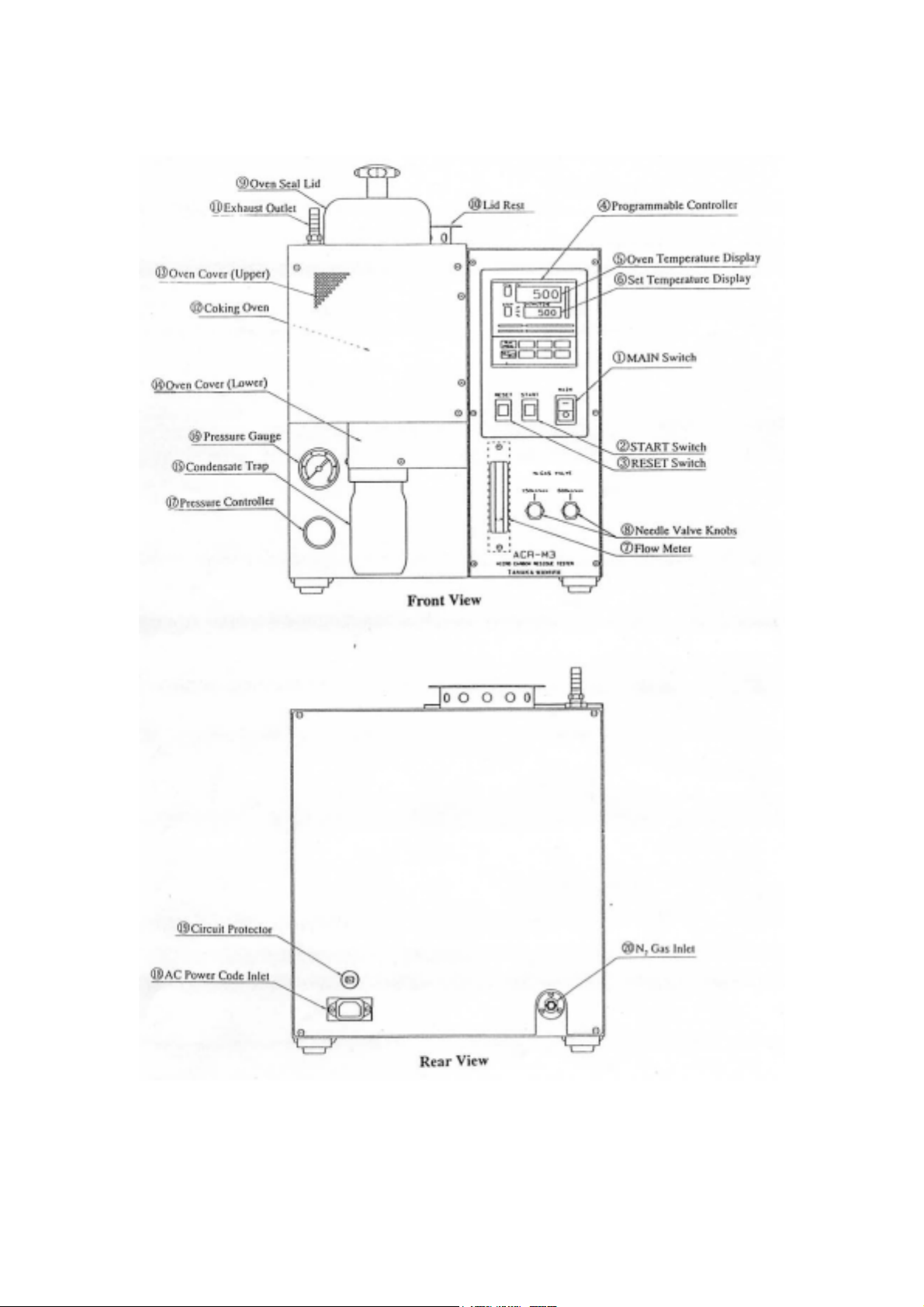
(1) With the oven at less than 100℃, place the vial holder into the oven chamber and
secure lid. When placing the vial holder, care should be taken not to touch the
thermocouple with sample basket feet.
(2) Confirm the nitrogen gas pressure gauge indicates 150kPa and the gas flow meter
shows 150ml/min, then press the START switch.
(3) The flow rate of nitrogen increases to 600ml/min automatically for the first 10
minutes after pressing the START switch. If the flow rate is not 600ml/min, adjust
N2 needle valve for 600ml/min (0.60L/min by flow meter).
(4) After this, the temperature(1) and flow rate of nitrogen are controlled as indicated
in Fig. 2.To complete the temperature and flow program(2) in 98 minutes.
(5) The buzzer intermittently sounds for about 10 seconds and “P.End” is shown on
the setting temperature display on the program controller.
(6) After “P.End” is indicated, press the RESET switch. The programmable controller
is reset and the “P.End” disappears.
(7) When oven temperature is less than 250℃, place the lid to the lid rest to cool down
and remove the vial holder using hook for further cooling in desiccator.
(8) Start the next test or turn the MAIN switch OFF(3) after the oven temperature falls
below 100℃.
Note 1 - For the safety, programmable controller cuts the heater output and sounds
buzzer continuously when the oven is abnormally heated above 550℃. Furthermore, a
separate circuit performs the same function when the oven heated above 600℃.
Turn off the MAIN switch and resolve the trouble before starting your next test.
Note 2 - ACR-M3 is preprogrammed to run carbon residue test. The detail of the
program is described under the procedure of the ASTM D4530.
Although the program has been entered and then locked prior to shipment, no attempt
should be made to alter the program. If, on the other hand, any variance from the
prescribed test conditions is found, consult Tanaka or its distributor for re-adjustment.
Note 3 – After resetting the Tester or when the Tester is idling, the nitrogen gas flow
rate is set at 150ml/min. With the MAIN switch turned off, the nitrogen gas flow stops

10
for saving gas. However, do not place a hot lid on the rest with the MAIN switch turned
off.
Fig. 2 Temperature and Flow Program
4.5 Final Weighing
Transfer sample vials to desiccator and allow vials to cool to room temperature. Weigh
the cooled vials to the nearest 0.1mg and record. Handle the vials with forceps.
4.6 Calculation
Perform appropriate calculations with weights found. % residue is the weight of final
vial (minus clean vial weight) divided by weight of original vial with sample (minus
clean vial weight).
5. Parts and Consumables, Making Self Diagnosis, and Maintenance
600ml/min
150ml/min
END
START
102
6230 39 44 4710
100
200
300
500
490
460
400
375
Setting
Temperature ℃
Time(min)
N2Flow Rate

11
!
CAUTION For consumable items and replacement part use only genuine
parts supplied by Tanaka.
5.1 Parts and Consumables
When ordering parts and consumables for this Tester, put “Model ACR-M3” and
Code# in front of the part name, since parts with similar description for different
models exist. Also, attach the serial number information to the order. For more detail,
contact Tanaka or its authorized distributor.
Tab. 3 Spare Parts and Consumables for ACR-M3
Code # Parts Name
010-01-003
010-01-005
010-00-007
ACR-02-001
ACR-02-002
ACR-02-003
ACR-03-001
ACR-02-401
ACR-02-402
ACR-02-015
ACR-02-413
260-02-002
Small Vials (100/box)
Medium Vials (50/box)
Large Vials (50/box)
Holder for Large Vials
Holder for Small and Medium Vials
Holder for Mixed Vials
Condensate Trap (vinyl laminated)
Packing for Condensate Trap
Hook for Holder
Oven Seal Lid Assembly
Insulation for Oven Seal Lid
Programmable Controller PC-935 (Sequence Programmed)
5.2 Periodical Inspection and Cleaning
After continued use, the exhaust port of coking oven tends to be plugged with
condensate and/or cake which increases the internal pressure of oven, and as a result

12
gas leakage occurs at the seal. Also, in case coke builds up on the sealing surface of
coking oven and/or lid, the seal gets leaky, resulting in gas leakage.
It has been reported that the gas leakage alters the rate of sample evaporation, and as a
result the test data may be affected. Thus, it is highly recommended that the coking
oven and piping be routinely inspected and, as needed, cleaned.
For a moderate rate of usage, it is recommended that such routine maintenance be
carried out at least once every half year; for heavier duty usage, the maintenance must
be done on a monthly or even weekly basis. In case one of the followings is observed,
carry out the cleaning procedure at once:
-Smoke leaking from the seal
-Not much condensate producing in the trap
-Condensate found around the seal
5.2.1 Inspection Procedure
Tab. 4 Inspection Procedure
Steps WHERE to
inspect
WHAT to inspect
#1 Sealing between
oven and lid
Any condensate built-up? Any tar sticking?
<Inspect visually>
#2 Exhaust port Any portion plugged? <Inspect visually>
#3 Exhaust hose
connected to
exhaust outlet
Hose bent downward and/or any condensate built
up in the hose?
<Inspect visually>
#4 Condensate trap Smoke not leaking? Packing working properly?
Screw thread of the trap not damaged?
<Inspect visually>
Fig. 3 Where to Inspect
5.2.2 Cleaning Procedure
! WARNING Carry out cleaning with electric power off and AC power cable
Exhaust Hose
Exhaust Outlet
Lid Assembly
Oven Lip
Coking Oven
Exhaust Port
Packing
Condensate Trap

13
unplugged to avoid electric shock.
Oven and lid gets extremely hot. Wait till they cool down to
prevent burn.
5.2.2.1 Cleaning Oven Lip (Sealing Surface)
Clean the oven lip using fine sanding paper (#400) to remove the deposit. Make sure
that the oven lip is not scratched.
5.2.2.2 Cleaning Sealing surface of Lid
Clean the sealing surface using a fine sanding paper (#400) to remove the deposit. Or,
remove the plug from the lid and then burn it in an electric furnace at 500℃for 2 hours
for cleaning.
<How to disassemble the lid Assembly> (See Fig. 4)
(1) Hold the lid assembly upside down and disengage the retainer ring using the tip of a
small screw driver.
(2) Remove the plug-insulator sub-assembly, and loosen the fixing screw to
disassemble the sub-assembly.
Fig. 4 Lid Assembly
5.2.2.3 Cleaning Exhaust Port
(1) Remove the exhaust hose and condensate trap.
(2) Lean the ACR-M3 to the right to sit it on its right side panel.
(3) Scrub the deposit on the inside wall of exhaust port of oven using a file or stick.
6. In Case of Abnormal Operation or Trouble
! CAUTION If even a “minor” abnormalit
y
is detected, stop usin
g
the Tester
Sealing
Surface
Lid Cover
Retainer Ring
Fixing Screw
Insulation for
Oven Seal Lid
Plug

14
immediately and then try to locate the problem. If the trouble
cannot be identified/fixed, consult Tanaka authorized
distributor.
Tab. 5 Trouble Shooting
Status Symptom Possible Causes Remedy
MAIN switch
ON
Nothing appeared on
programmable
controller
The head of the circuit protector
button has come out
Bad programmable controller
Others
Press the head of the circuit
protector button
Programmable controller
needs to be replaced
Consult Distributor
Process does not start N2gas pressure is below 80kPa
Bad programmable controller
Others
Adjust to 150kPa
Programmable controller
needs to be replaced
Consult Distributor
Sequence does not
progress
Bad programmable controller
Others
Programmable controller
needs to be replaced
Consult Distributor
N2gas does not flow
(600ml/min)
Needle valve is closed
Exhaust port is plugged
Others
Adjust needle valve
Check and clean
Consult Distributor
START switch
ON
Smoke leaking from the
oven lip
Bad seal
Exhaust port is plugging
Others
Clean lid and oven
Clean exhaust port
Consult Distributor
RESET switch does not
work
Bad programmable controller
Others
Programmable controller
needs to be replaced
Consult Distributor
RESET switch
ON
Low N2gas pressure N2gas bomb pressure is low
N2gas line pressure is low
Replace N2gas bomb
Adjust N2gas line pressure
<How to remove the programmable controller>
!
WARNING Remove the programmable controller with electric power off
and AC power cable unplugged to avoid electric shock.
Hold the up and down hollow, then pull the body from the case while pushing up the
hook which is located at the bottom of controller.
7. Post-sales Servicing
For ordering consumable items or parts or to request servicing, please contact Tanaka
authorized distributor.
Please note that spare parts that are necessary to maintain/regain the function of this
Tester is kept in inventory for a minimum of 5 years after the delivery of this Tester.
8. Precaution in Case of Loss of Instruction Manual
The Instruction Manual is a part of this instrument. In case it is lost, please request a
new copy to Tanaka or its authorized distributor.
Also, it is highly recommended that the address and telephone number of Tanaka
and/or its authorized distributor be kept separately from this Manual.
9. Caution When Transferring This Tester
If this Tester is transferred or sold to a third party, please inform Tanaka or its
authorized distributor. Wrong source voltage and/or AC frequency could cause

15
damages or malfunctioning. In case of transferring this Tester, make sure to attach this
Instruction Manual.
10. Specification
(1) Conforming standard test methods:
ISO 10370, ASTM D4530
(2) Coking Oven: with circular heating chamber, φ85mm by 105mm deep,
made of stainless steel
Heater: Pipe type, 500W ×2, made of stainless steel
Heating Range: Up to 500℃
(3) Process Controller: Digital Programmable Controller, model PC-935
(4) Switches: MAIN, START and RESET switches fitted on the front
panel
(5) Thermocouple: JIS J-type (Fe-Constantan)
(6) N2Gas Supply Unit:
Pressure Controller (2nd stage regulator):
Primary Pressure: 1400kPa max.
Control Range: 20 to 750kPa (usually 150kPa)
Pressure Gauge: φ42.5mm, full scale 0.7MPa
Pressure Switch: The tester stops operation with the secondary pressure less
than 80kPa
Flow Meter: 0.1 to 1L/min
Flow Rate: Automatically regulated at 150ml/min and 600ml/min,
according to ASTM D4530
Inlet: φ10mm hose nipple
(7) Condensate Trap: 200ml vinyl laminated glass jar with threaded mouth
(8) Exhaust Outlet: φ10mm hose nipple
(9) Control Unit Cooling: Air-cooling by a propeller fan to be used also for cooling the
oven seal lid
(10)Dimensions: 350W×390D×460H (mm)
(11)Weight: 21kg
(12) Utility and others:
Power Supply: AC100/120V or 220/240V 50/60Hz 1.6kW(max)
N
2Gas Supply: Bomb 200 to 500kPa or from piping
(Consumption: Approx. 40L of N2Gas/test)
Exhaust: To be made to an exhaust line or fume hood
Room Temperature: 10 to 30℃
Humidity: 80%RH or less (no condensation)
Others: An analytical balance is required for weighing
(13) Standard Accessories:
Description Quantity
Small Vials (100/box) 1
Large Vials (50/box) 1
Holder for Small Vials 1
Holder for Large Vials 1
Hook 1
Condensate Trap 1
Oven Seal Lid 1

16
AC Power Code (AC100/120V: 3.0m, AC220/240V: 2.5m) 1
Braided Hose for N2Gas (3m) 1
Wire Band for N2Gas 2
Rubber Hose for Exhaust (5m) 1
Hose Band for Exhaust 1
Instruction Manual 1
(12)Optional Accessories:
Medium Vials (100/box): Test for ISO 10370
Holder for Mixed Vials (small/medium×6 and Large×3)
Auxiliary Cooling Fan Unit: To help cooling the oven quickly
1st Stage Regulator for nitrogen gas bomb : model WR-11-NP
Primary Pressure: 15000kPa max.
Control Range: 0 to 500kPa
Materials: Brass
Screw size: PT 1/4” or NPT 1/4”
*The contents of this specifications are subject to change without prior notice.
Table of contents
Other Tanaka Test Equipment manuals