Tansun Quartzheat CARN4 1X1000H User manual

©Tansun Limited 2012 Part No. 043082 Issue. 1b
Reference Manual
Carnival
Mk. 4 SK15
MODELS FOR UK & EUROPE:
CARN4 1X1000H, CARN4 1X1300H - HORIZONTAL MOUNTED MODELS
CARN4 1X1000U, CARN4 1X1300U - ANGLED MOUNTED MODELS
Spectrum House, Unit 1, Ridgacre Road, West Bromwich,
West Midlands, B71 1BW, England.
Tel +44 (0)121 580 6200 - Fax +44 (0)121 580 6222

R i s k o f F i r e
Keep combustible materials such as furniture, papers, clothes and curtains at least 1.8m (6 feet) from the front of the
heater and away from the sides and rear. If the heater is to be used outside (under an appropriate canopy), we
recommend that an indoor socket is used.
I n t r o d u c t i o n
The Carnival heater produces radiant heat like the sun, warming people and objects and not the air in between, providing the only form
of heat that will not blow out or away. The Carnival heater is primarily designed for indoor use but can be used outside providing it is
situated under an appropriate canopy.
Please read the enclosed instructions carefully before use. The safety of this heater is guaranteed only by the correct usage
in accordance with these instructions, therefore it is recommended that they are retained for future reference.
S p e c i f i c a t i o n
T a b l e 1 . K a n d E u r o p e a n H e a t e r s
Use MCB Type 3.
Voltage Total Current Min height Min distance Min distance Dimensions Weight Mounting
Model
(V) Power (A) from floor from ceiling from side wall W x H x D (kg) Orientation
(W)
(m) (m) (m) (mm)
CARN4 1X1000H 230 1000 4.3 2.0 0.3 1.0 392 x 100 x 113 2.4 Horizontal Only
CARN4 1X1000U 230 1000 4.3 2.0 0.3 1.0 392 x 100 x 113 2.4 Horizontal or Angled
CARN4 1X1300H 230 1300 5.7 2.0 0.3 1.0 392 x 100 x 113 2.4 Horizontal Only
CARN4 1X1300U 230 1300 5.7 2.0 0.3 1.0 392 x 100 x 113 2.4 Horizontal or Angled
2
C a u t i o n
Before using this appliance
- Check that the voltage indicated on the type plate corresponds to the mains supply voltage.
- Ensure that the heater has been securely fastened in its final mounting position.
Do not locate the heater immediately below a socket outlet.
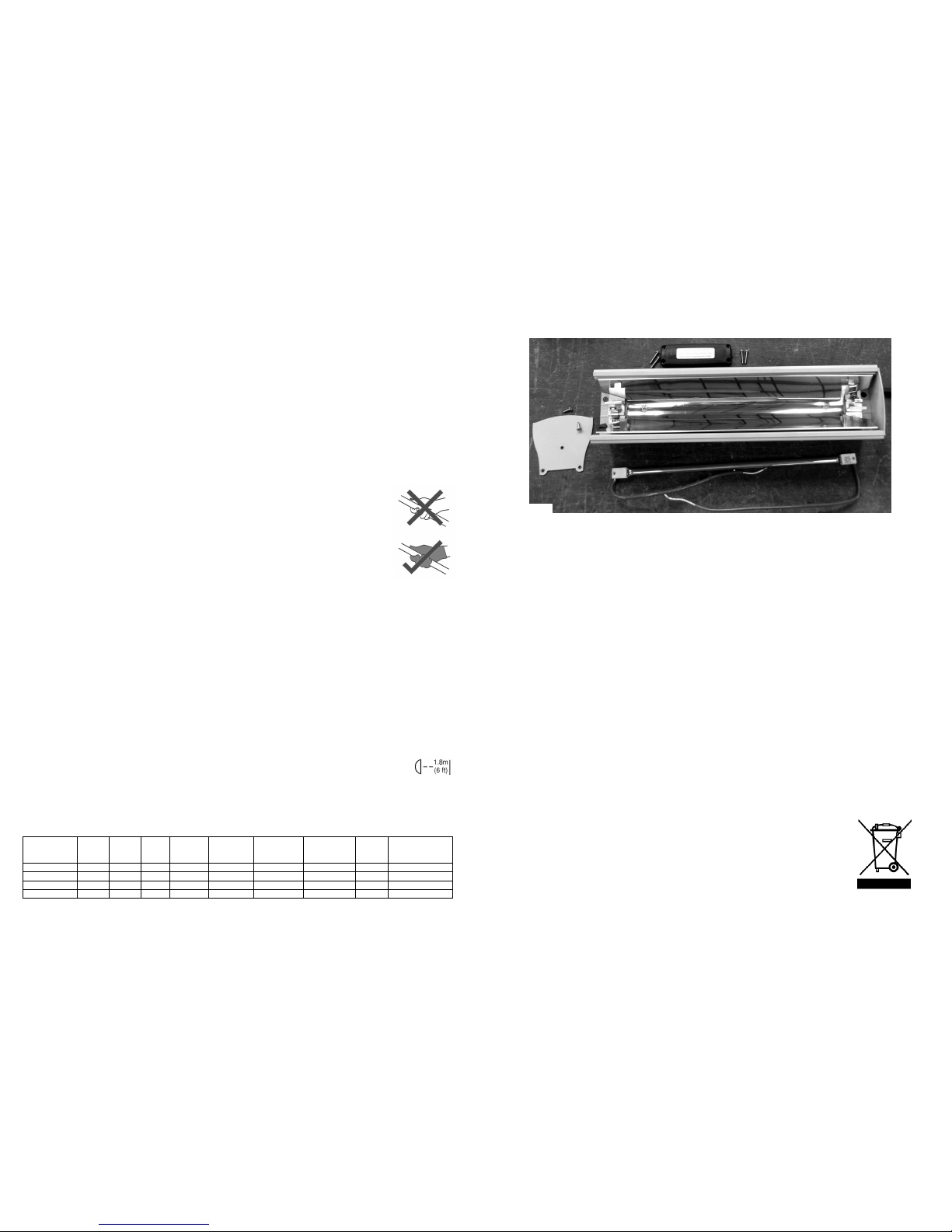
Remove the plug from the mains socket during installation, cleaning and/or replacing the lamp. Always ensure that the
lamp is cool.
Do not handle the halogen lamp with bare hands. If it is inadvertently touched, remove finger marks with a lint-
free soft cloth and methylated spirit or alcohol. Otherwise, the finger marks will burn into the quartz glass of the
lamp causing premature heater failure.
Do not use an extension lead with this product.
Keep the mains cable away from the body of the heater which will get hot during use.
Do not cover or obstruct the heater while it is in use.
This appliance is not intended for use by persons (including children) with reduced physical, sensory or mental
capabilities, or lack of experience and knowledge, unless they have been given supervision or instruction concerning
use of the appliance by a person responsible for their safety. Children should be supervised to ensure that they do not
play with the appliance.
Do not insert any object through any slot or opening in the heater.
Do not use if guard is not present.
Do not install less than the minimum mounting distance from the floor.
Do not touch the heater when it is switched on, as the body gets hot.
Do not use the heater in a damp area, for example a bathroom or near to a swimming pool.
Warning - this product must be earthed.
F o l l o w i n g i n f o r m a t i o n i s o n l y f o r E - m e m b e r s t a t e s :
The use of this symbol indicates that this product may not be treated as household waste. By ensuring this
product is disposed of correctly, you will help prevent potential negative consequences for the environment
and human health, which could otherwise be caused by inappropriate waste handling of this product. For
more detailed information about recycling of this product, please contact your local council, your household
waste disposal service or the shop where you purchased the product.
7
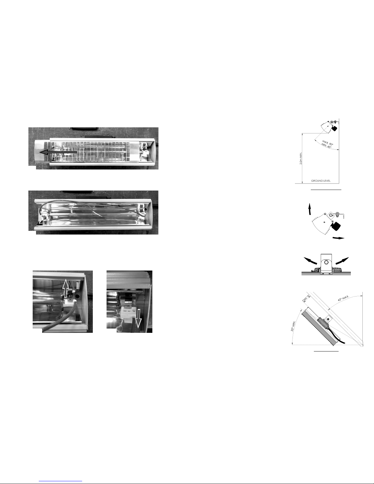
12. Refit the new lamp in reverse order ensuring that no wires get trapped and all screws are fully tightened.
11. The heater should now be broken down as shown in Fig. 11. Note that one of the lamp wires is shorter than the other. Ensure
your new lamp wires are the same length and its fitted the same way around as the original.
Fig. 11

6
Fig. 9
Fig. 10b
9. Pull the lamp wires through the two access holes so it is ready to be unclipped and removed from the heater (Fig. 9).
10. The lamp is held in at each end by spring clips that hold the lamps ceramic caps in the lamp holders. Pull the clips back (Fig. 10a)
far enough to allow the ceramic caps to be lifted up (Fig. 10b) at both ends and remove the lamp from the heater.
Fig. 10a
8. Turn the heater body over and slide the guard out of the heater by pushing it towards the end where the end cap is removed (Fig. 8).
Fig. 8
I n s t a l l a t i o n
The heater is fitted with 5.0 meters of supply cable and a moulded
plug, therefore it is unnecessary to open the terminal box in order to
carry out normal installation of this product and should not be
interfered with.
We recommend using a RCD where applicable.
Please observe the minimum safe distance between the heater
body and any inflammable surfaces.
If the supply cord becomes damaged, it must be replaced by the
manufacturer, its service agent or a similar qualified person in
order to avoid a hazard.
The Carnival heater is primarily designed for indoor use and is not
waterproof but can be used outside under an appropriate canopy
providing the ‘minimum distance from ceiling’ in table is adhered
to. When the electrical connection is outside, it is recommended
that a waterproof socket is used for the connection/terminal.
Otherwise, the plug should be connected to a socket indoors.
If in any doubt, please contact a suitably qualified electrician.
M o u n t i n g
The Carnival SK15 models can be mounted in a horizontal (Fig. A)
or angled (Fig. D) manner depending on the model type - see
Table 1 for mounting orientation.
When mounting the heater horizontally, do not position the heater
at an angle more than 90° and less than 45° from the vertical
mounting surface as shown in Fig. A. Ensure the terminal box is on
the underside of the heater when mounting.
When angled mounting the heater, ensure to leave a gap between
the heater and mounting surface (See Fig. D - DIM ‘A’). The heater
should always be angled downwards when mounting this way with
the cord from the terminal box at the bottom of the heater - see
Fig. D. Do not position the heater at an angle more than 45° and
less than 30° to the horizontal as shown.
Always allow the heater to cool before attempting to reposition/
move. Never attempt to move the heater while it is switched on!
Observe the minimum safe distance between the heater body and
inflammable surfaces and objects when mounting.
Please refer to Table 1 for the recommended positioning of the
heater.
Keep out of the reach of children.
1. Securely fasten the L-shaped heater bracket to the mounting
surface using the fixing holes in the bracket. Please refer to Table 1
for recommended positioning of the heater.
2. Fix in the required angular position by tightening the fixing bolt on
the bracket at the rear of the heater.
3. The heater bracket assembly can be used to adjust the direction of
the heater up and down (see Fig. B) and side to side (see Fig. C). This
is done by loosening the bolts fixing the heater to the bracket, and
then retightening once the correct position is achieved.
Always isolate the heater from the mains supply when adjusting the
angular position.
Fig. A
Fig. B
Fig.
Fig. D
HORIZONTAL MOUNTING
ANGLED MOUNTING
3

Fig. 3a Fig. 3b
3. The heater will now be free to slide off the back plate (Fig. 3a). Gently slide the heater body away from the open end as shown in
Fig. 3b to it from its mounting.
R e p l a c i n g t h e L a m p
If you are in any doubt about following the procedure below, please contact us for technical assistance. The mains power
should be disconnected before any attempts are made to replace the lamp. The following should be carried out with
compliance to I.E.E. regulations. Please read the notes above with regards to handling and buying a replacement lamp
before proceeding.
1. Ensure the heater and lamp are cool and the power supply is disconnected by removing the plug from the socket outlet as shown in
Fig. 1.
2. Remove one of the heater end caps by removing the three screws with a pozi-head screwdriver as shown in Fig. 2.
Fig. 1 Fig. 2
4
Y o u r R e p l a c e m e n t L a m p
It is important that your replacement lamp is exactly the same as the one it was supplied with. Failure to fit the exact
same type could cause the heater to fail or even become dangerous.
Please contact Tansun Limited or your service agent to purchase your replacement lamp and state the model number
of the heater you wish to fit the lamp to.
H a n d l i n g t h e R e p l a c e m e n t L a m p
Your new lamp should not be handled with bare hands. Remove finger marks with a soft cloth and methylated spirits
or rubbing alcohol. Finger marks will burn into the lamps quartz glass causing premature failure.
M a i n t e n a n c e
In the event of heater failure please contact the retailer or seller in the first instance. For spare parts or advice, please contact Tansun
Limited.
Disconnect from the power supply by removing the plug from the mains socket before commencing any maintenance procedure
including cleaning.
To ensure optimum heat effectiveness, it is recommended that the reflector is kept clean. If dirt appears to build up on the reflector,
the front safety guard should be removed and the reflector wiped with a lint-free cloth before re-fitting.
The heater is supplied with a safety guard. In the unlikely event that this gets damaged, please contact Tansun Limited for an
immediate replacement.
4. The back plate should now have the heater body removed from it (Fig. 4a) and can be placed on a safe, flat work surface (Fig. 4b) to
proceed with the lamp change.
Fig. 4a
5
Fig. 7
Fig. 6a
Fig. 4b
5. Remove the four screws (Fig. 5) from the terminal box and lift off the lid.
Fig. 5
7. From inside the heater body, gently pull the lamp wires through the sealing gasket so the lamp wires exit the terminal box and are
free as shown below in Fig. 7.
6. Remove the connector block retaining bridge by removing the screw and lifting out. This will allow the connector block to be lifted
out of its locating lugs to allow for better access when connecting the new lamp terminals. For now though leave it in its locating lugs
and unscrew the connector block screws as highlighted (Fig. 6a) and remove the white lamp wires so they are free (Fig. 6b).
Fig. 6b
RETAINING BRIDGE
This manual suits for next models
3
Other Tansun Quartzheat Electric Heater manuals
Popular Electric Heater manuals by other brands

Intertec Data Systems
Intertec Data Systems CP MICROTHERM DBNA operating instructions

Bosch
Bosch HK050-1XXX-RE installation instructions

Qlima
Qlima EFE 2018 operating manual

King Electrical
King Electrical LPW1227 installation instructions

EUROM
EUROM CK2003T Instruction booklet

DeLonghi
DeLonghi HVR 9032 instruction manual

Sylvania
Sylvania HUDSON SR989-BK instruction manual

HomeTech
HomeTech BLT-999B-9 Operation manual

DeLonghi
DeLonghi EW 7707CM manual

Clarke
Clarke DEVIL 3003B Operation & maintenance instructions

VOLTOMAT HEATING
VOLTOMAT HEATING VOLTW0500 instruction manual

Dimplex
Dimplex ZHE 050 Installation and operating instructions