Taoglas ZRM500 User manual

SPE-16-8-081/A/DC
ZRM500 High Performance
Rugged Mobile Smart Antenna Platform
ZRM500.A.02
Product Specification & Quick Start Guide

SPE-16-8-081/A/DC
Contents
Product Description .....................................................................................................................................................................03
Key Benefits ....................................................................................................................................................................................04
Specifications ................................................................................................................................................................................05
Quick Start Guide...........................................................................................................................................................................06
Disclaimer
Taoglas makes no warranties based on the accuracy or completeness of the contents of this document and reserves the right to make changes
to specifications and product descriptions at any time without notice. Taoglas reserves all rights to this document and the information contained
herein. Reproduction, use or disclosure to third parties without express permission is strictly prohibited.
For more sales or support contact

SPE-16-8-081/A/DC
Product Description:
ZRM500 High Performance Rugged Mobile Smart Antenna Platform
The ZRM500 sets a new bar for performance, level of integration, and ease of installation in the M2M smart
antenna platform space. It delivers the most advanced communications, networking, and tracking technologies
in a waterproof enclosure that can be used in almost any environment.
The ZRM500 is a fully integrated 2*2 4G LTE, 2*2 Wi-Fi a/b/g/n/ac, concurrent GNSS, 1621MHz SatCom Satellite
SBD. The gigabit ethernet enabled router and power injector architecture provides both data and power on a single
cable for ease of installation and keeps power consumption to a minimum.
The Smart Antenna is the ideal solution for:
• 4G High Bandwdith Mass Transportation Systems
• Real-time HD Video Broadcasting
• Remote Monitoring
• Broadband Connectivity
• Global Asset Tracking
The smart antenna is designed to withstand the harshest of environments. It is operational over the entire industrial
temperature range -30C to +70C. It is built with toughened, impact resistant ASA and the housing is UV resistant.
Tested to ISO 16750-2,3,4, the device can withstand automotive vibration and electrical transients. The device
includes all required antennas enclosed within a single IP69k vandal resistant enclosure.
Designing both the radios and antennas together in a single package removes cable and connector RF loss and
reduces installation costs. Just a single CAT5e Ethernet Cable 44, is required to connect the device to the network
and power. A separate automotive grade power injector module enables the single cable installation and provides
flexibility in running power and data.
The ZRM500 Multi-Radio Smart Antenna includes:
• 2x2 MIMO 4G LTE and 3G HSPA
• 2x2 MIMO dual band 802.11 a/b/g/n/ac Wi-Fi
• 1621MHz SatCom Satellite SBD (L-band)
• GPS
• Built-in antennas for all radios

SPE-16-8-081/A/DC
The ZRM500 has an extremely simplified installation and mounting procedure. The smart antenna sits in a single
punched hole made in any rigid sheet surface and is secured with single nut from the bottom side. Once secure, the
unit itself and the interface to the mounting surface are fully waterproof and pressure washer safe.
The product runs embedded Linux and features enterprise grade router configurability. The router has a 802.11a/b/
g/n/ac client and access point capability, best in class GPS performance, low power sleep modes and an easy to
use configuration interface. Configuration is done over a secure web interface or SNMP, locally or remotely.
Key Benefits
• One enclosure, no RF cables or connectors
• Lower installation costs, less labour, less material to install
• Higher radio performance with direct antenna connection eliminates RF losses from coaxial cables and connectors
• 1621MHz SatCom and GPS via Ethernet, available to any device on the network simultaneously
• 2x2 MIMO for both Wi-Fi and Cellular for highest speeds in the industry
• Most powerful processor in class
• Most rugged enclosure in class
• Highly adaptable power and network provisioning for any installation scenario
• Electrically isolated power supply
• 1621MHz SatCom satellite messaging for mission critical location and data reporting

SPE-16-8-081/A/DC
Mechanical
Specifications
System Features
High performance processor system: 800MHz ARM Cortex Dual Core
A9 microprocessor with hardware encryption accelerator running
embedded Linux
VPN support: VPN (SSL v2, TLS v1) SSH server, SCP, SFTP
2x2 MIMO LTE with fallback to 3G & 2G (EU only)
US Frequency Bands: LTE 2,4,5,13 & 17
UMTS 850, AWS, 1900, 2100
GSM 850, 1900
Highly configurable routing of IP trac
Wi-Fi: 802.11a/b/g/n/ac with 2x2 MIMO and speeds
up to 866.7Mbps (80MHz channel)
Wi-Fi Access Point or Client mode support
2.4GHz or 5.8GHz operation
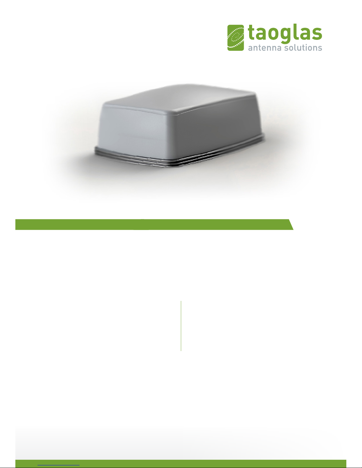
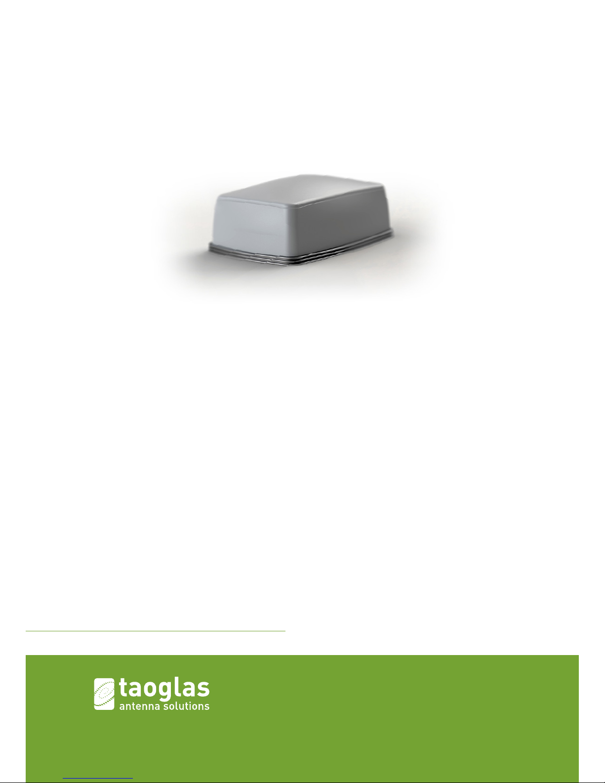
Enclosure: White, toughened ASA, UV stabilized
IP67 waterproof and IP69K pressure washer safe
Dimensions: 177mm x 122mm x 65mm
Weight: 676g
Through hole permanent (screw) mount with mounting plate
Temperature: -40º to +70º C (operating)
-40º to +85º C (storage)
Humidity: 95% R.H. @ 50º C non-condensing
Shock and Vibration: ISO 16750-3
Environmental Ratings & Certifications
TCP/IP, UDP/IP, DHCP, HTTP, IP Router, PPP,
HTTP Web server, Telnet DHCP server,
DDNS, DDNS Client, NAT, SNMP, TAIP, TSIP, TFTP, IP port forwarding
72-channel GPS receiver, GPS/Glonass support with Assistance
Acquisition Sensitivity -148dBm, Tracking Sensitivity -167dBm
NMEA output via TCP connection or optional serial interface
EU Frequency Bands:
LTE 1,3,5,7,8,20
UMTS 850/900/1900/2100
GSM 850/900/1800/1900
High performance 1621MHz SatCom 9603 satellite modem
Ability to send GPS position information through the local
web UI via a button.
Easy replication of configuration to simplify deployments
Power consumption: under 10 Watts in-use
Connectors: 1-RJ45 10/100/1000Mb Ethernet and power
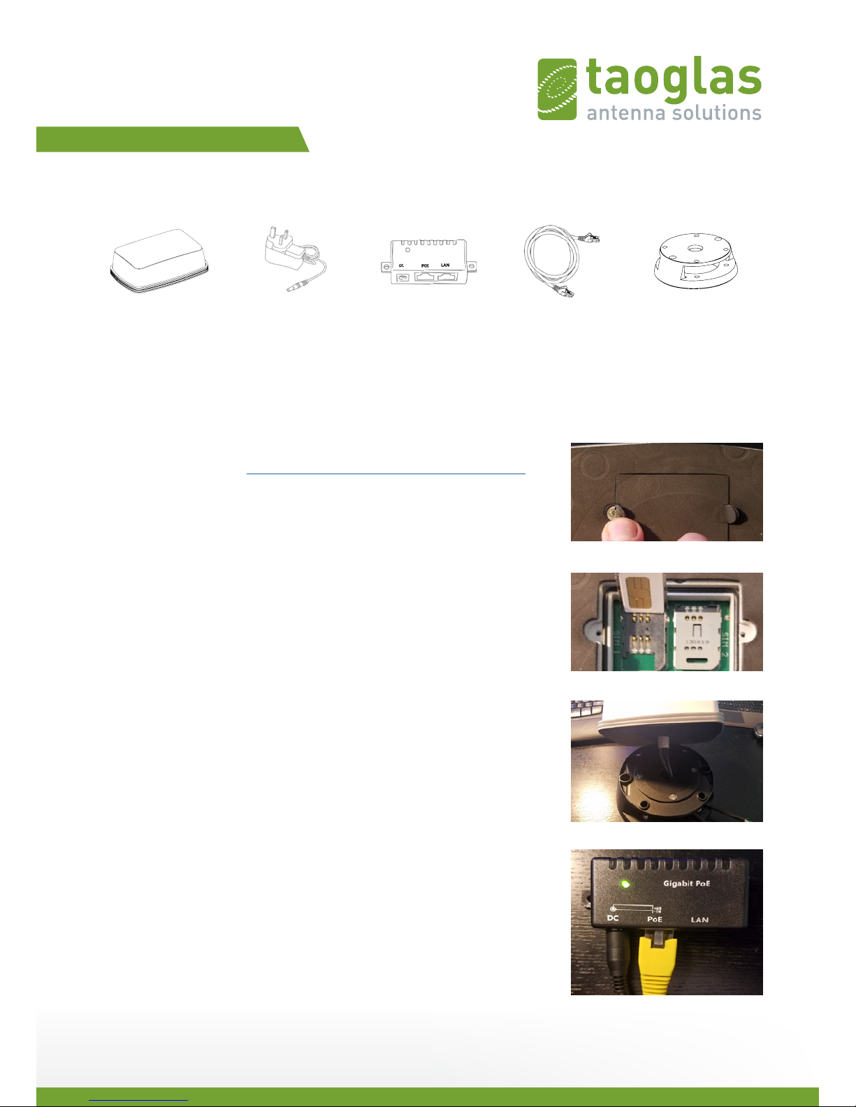
2-Protected SIM holders
Power break out box allows for using vehicle power
Auto-switched power path and trickle charger for
Magnetic-Mount and Pole-Mount options available
Device is fully certified including FCC, CE, IC, PTCRB, applicable Carriers
including Vodafone, Verizon and AT&T.
EMC/EMI: ISO 16750-2,
122mm
65mm
177mm

SPE-16-8-081/A/DC
Quick Start Guide
Package Contents:
The following list of items are required to get the ZRM500 configured prior to bench testing:
(1) ZRM500 Unit
(1) Power Over Ethernet (PoE) switch.
We recommend the ‘WS-GPOE-1-24v30w’, which includes a 24-volt power supply.
This can be purchased here: https://find-a-poe.com/product/WS-GPOE-1-WM-24v30w/
(1) Ethernet cable
(1) Phillips head screwdriver for an M2 screw
(1) Active LTE / 4G cellular account with 2FF SIM Card
(1) Network APN
(1) Benchtop mounting bracket
Step 1: Install Sim Card
Please ensure your SIM card is installed before powering the device. Peel back
the insulation covering the screw holes on the bottom of the ZRM500 and
remove the SIM card cover, see Figure 1. The default SIM tray is ‘SIM 1’. Insert your
2FF SIM and ensure the SIM tray cover slides and locks into place, see Figure 2.
Reattached the SIM card cover.
Step 2: Attach the Desk Mount
Using your desktop mounting bracket, feed the ZRM500 cables through the top
hole and out the side of the mounting bracket as shown in Figure 3. Use the nut
to firmly tighten the ZRM500 to the mounting bracket
Step 3: Connect Power Over Ethernet (PoE)
Connect your ethernet cable and power supply cable to the PoE unit. Then
connect the opposite end of your ethernet cable to the ethernet port on
the ZRM500. Plug in your power supply and ensure the LED on the PoE unit
illuminates green.
ZRM500 Device PoE Unit24v Power Supply Ethernet Cable Benchtop Bracket
Figure 1
Figure 2
Figure 3
Figure 4

SPE-16-8-081/A/DC
Step 4: Connect to ZRM500 Wi-Fi
Open your computer’s Wi-Fi Network List and connect to your ZRM500 router. It
may take about one minute for the ZRM500 to fully power up and broadcast its
Wi-Fi ID. The ZRM500 Wi-Fi ID will look similar to Figure 5.
Connect to “zrm500-xxxxxxxx”. Please note that no password is set by default.
Step 5: Connect to ZRM500 Login Page
Open your web browser and type http://192.168.1.1 which should bring you to the ZRM500 login page.
Enter the default username and password, see below and then click the “Login” button. See Figure 6.
Username: remote
Password: zrmea7nd4
You will now see the ‘Status’ webpage. Click on the word “Cellular” then locate the APN field and enter your APN
(APN is provided by your service provider). Click on the “Save and Apply” button. See Figure 7. Your ZRM500 is
now provisioning on the cellular network. This will take about 2 minutes. Once it has fully provisioned, you will see
the State filed change to Registered. Once it is registered you have successfully established a cellular network
connection. See Figure 8.
Figure 5
Figure 6
Figure 7 Figure 8

SPE-16-8-081/A/DC
Table of contents
Other Taoglas Antenna manuals