manuals.online logo
Brands
  1. Home
  2. •
  3. Brands
  4. •
  5. Raychem
  6. •
  7. Cables And Connectors
  8. •
  9. Raychem Gardian W51 User manual

Raychem Gardian W51 User manual

Description
Gardian™ W51 120 V pre-assembled self-regulating heating cables are
designed for residential and commercial metal and plastic pipe freeze
protection and roof & gutter de-icing applications. Gardian W51 heating
cables are available in 6, 12, 24, 50, 75 and 100 foot lengths, and each
comes assembled with a 30-inch power cord and plug.
Kit contents
1 Gardian W51 pre-assembled electric heating cable
2 Roof and gutter labels
2 Pipe labels
Additional items required but not supplied for pipe applications
Waterproof thermal insulation (e.g. preformed foam)
Ground-fault protected outlet (GFCI)
Raychem®H903 Application Tape and Electric Traced Labels
Additional items required but not supplied for roof & gutter applications
Raychem H913/H914 Roof Clips (10 clips for each 7 linear feet of
roof edge)
Raychem H915 Hanger Bracket (1 for each downspout, 2 if looping)
UV Resistant cable ties
Ground-fault protected outlet (GFCI)
Approvals
718K Pipe Heating Cables
60J9 Residential and Mobile Home Pipe Heating Cables
877Z De-Icing and Snow Melting Equipment
Desig. 3A, 3B, 3C, 2E, 3D
Fire and shock hazard. This product is an
electrical device that must be installed
correctly to ensure proper operation and to
prevent shock or fire. Read these important
warnings and carefully follow all the
installation instructions.
• To minimize the danger of fire from sustained
electrical arcing if the heating cable is damaged
or improperly installed, and to comply with the
requirements of Tyco Thermal Controls
and national electrical codes, ground-fault
equipment protection must be used on each
heating cable branch circuit. Arcing may not be
stopped by conventional circuit protection.
• For pipe freeze protection applications, use
only fire-resistant insulation materials such as
preformed foam or fiberglass.
• Do not damage the heating cable and power
cord or plug. Remove any damaged cables
from service immediately.
• Do not use any wire or metal clamps to attach
the cable to the pipe. Use tape (1/2 inch wide
to 1 inch wide) or plastic cable ties.
• Do not install the heating cable underneath any
roof covering for roof and gutter de-icing.
• Leave these installation instructions with the
user for future reference.
Installation Instructions
Gardian™W51
120 V pre-assembled electric heating cables for
pipe freeze protection and roof & gutter de-icing
®
WARNING:
Pipe freeze protection
Roof and gutter de-icing: standard roof
Roof and gutter de-icing: standing seam metal roof
2
Determine which Gardian W51 heating cable
you need for pipe freeze protection:
Use the tables to the right to select the correct
heating cable. Add 1 foot to your pipe length for
each valve or spigot on your pipe system.
The charts assume the lowest outside temper-
ature is 0°F (–18°C), with a minimum of 1/2"
thick waterproof, fire-resistant thermal insulation
(preformed foam). For protection to –20°F
(–29°C), use 1" thick insulation.
Important
All thermal and design information provided
here is based upon a “standard installation”:
heating cable fastened to a pipe and thermally
insulated. For any other method of installation or
application, consult Tyco Thermal Controls at
(800) 545-6258.
Product selection charts for pipes
Electrical codes
Articles 422 and 427 of the National Electrical
Code (NEC), and Part 1, Section 62 of the
Canadian Electrical Code (CEC), govern the
installation of Gardian heating cable for pipe
freeze protection and must be followed.
Important: For the Tyco Thermal Controls
warranty to be valid, you must comply with all
the requirements outlined in these guidelines.
All thermal and design information provided
here is based upon a “standard” installation
with heating cable fastened to an insulated
pipe. For any other application or method of
installation, consult Tyco Thermal Controls at
(800) 545-6258
General requirements for pipe freeze
protection:
• Gardian heating cables may be used on metal
and plastic water pipes but not on flexible
vinyl tubing (such as garden hoses).
• Gardian heating cables are not intended for
use
inside
any pipes, for freeze protection of
liquids other than water, or for use in classified
hazardous locations.
• Install with a minimum of 1/2" fire-resistant,
waterproof thermal insulation.
• Never use on any pipes that may exceed
150°F (65°C).
• Do not use an extension cord.
General instructions:
• Install only in accessible locations; do not
install behind walls or where the cable would
be hidden.
• Do not run the heating cable through walls,
ceilings, or floors.
• Connect only to ground-fault protected
outlets that have been installed in accordance
with all prevailing national and local codes
and standards and are protected from rain
and other water.
1
/
2
1
1
1
/
2
2
0 102030405060708090100
0 102030405060708090100
2
1
/
2
1
/
2
1
1
1
/
2
2
2
1
/
2
Pipe length (ft)
Pipe diameter (in)
Pipe length (ft)
Pipe diameter (in)
18P
18P
6P
6P
6P 12P
12P
12P 18P 24P
24P
24P
18P
18P
6P
6P
6P 12P
12P
12P 18P 24P
24P
24P
50P
50P
50P 75P
75P
75P 100P
100P
100P
50P
50P
50P 75P
75P
75P 100P
100P
100P
Table 1 Metal Pipes
Table 2 Plastic Pipes
Add 1 foot to the pipe length for each valve or spigot on your pipe system. If cable selected is longer
than the pipe, spiral it evenly along the entire pipe.
Pipe Freeze Protection
Tape or
cable ties
W51 heating
cable
12 inches
10 feet
Glass tape
(typical)
Heating
cable
Tape after
spiraling
heating
cable on
pipe
Wrap loops
in opposite
direction
Pull heating
cable loop
length
Apply glass
tape before
spiraling
heating cable
on pipe
Waterproof covering1/2" insulation
Pipe label
Tape or
cable ties
W51 heating
cable
12 inches
Waterproof covering
Pipe label
End view
1/2" insulation
3
Figure 1 Straight-traced installation
Figure 2 Spiral-traced installation
Heating cable installation
1. Prepare for installation.
• Store the heating cable in a clean, dry place.
• Complete piping pressure test.
• Prior to installing the cable, remove any
sharp surfaces on the pipe that might
damage the heating cable.
• Review the Gardian heating cable design
and compare to materials received to verify
that you have the proper Gardian heating
cable.
• Walk the system and plan the routing of
the Gardian heating cable on the pipe.
2. Position and attach heating cable to pipe.
• Be sure all piping to be traced is dry.
• Install heating cable, using straight tracing
Figure 1, or spiraling Figure 2.
• For straight tracing, install the heating cable
on a lower half of the pipe; for example, in
the 4 o’clock or 8 o’clock position.
• Be sure to install the additional heating
cable required for valves, flanges, etc. as
shown in Figures 1 and 2.
• When the design calls for spiraling, begin
by suspending a loop every 10 feet as
shown in Figure 2
.
To determine the loop
length, divide the Gardian length by your
pipe length and multiply by 10. For
example, if you are using a 50 ft Gardian
on a 40 foot pipe, leave a 12-foot loop of
heating cable at every 10-foot section of
pipe. Grasp the loop in its center and wrap
it around the pipe. Even out the distance
between spirals by sliding the wraps along
the pipe. Use glass tape to secure the
center of the loop to the pipe.
• Fasten Gardian heating cable to the pipe at
1-foot intervals using H903 fiberglass
application tape or nylon cable ties. Do not
use vinyl electrical tape, duct tape, metal
bands, or wire.
• If excess cable remains at the end of the
pipe, double it back along the pipe.
3. Check the installation.
• Prior to installing thermal insulation, make
sure the heating cable is free of mechanical
damage (from cuts, clamps, etc.) and
thermal damage (from solder, overheating,
etc.).
4
Cord label
Pipe label
Strain relief
Cable testing and maintenance
Using a 2500-Vdc megohmmeter, check the
insulation resistance between both of the
rectangular (power) prongs on the plug and
the round (ground) prong after installing the
heating cable. Minimum reading should be
1000 megohms.
Record the original values for each circuit, and
compare subsequent readings taken during
regular maintenance schedules to the original
values.
If the readings fall below 1000 megohms,
replace the Gardian W51 cable with a new
unit. Do not attempt to repair the unit.
WARNING! Fire and shock hazard.
Damaged heating cable can cause electrical
shock, arcing, and fire. Do not attempt to
repair or energize damaged heating cable.
Remove it at once and replace with a
new length.
4. Install thermal insulation.
• A reliable Gardian system depends on properly installed and dry,
weatherproofed thermal insulation.
• Ensure that at least 1/2" of preformed foam or equivalent thermal
insulation is used and that all piping, including valves, joints, and wall
penetrations, has been fully insulated as shown in Figure 3.
• For protection to -20°F (-29°C), use 1" thick insulation.
• Install the insulation on the piping as soon as possible to minimize the
potential for mechanical damage after installation.
• Be sure the Gardian W51 label is visible on the outside of the thermal
insulation.
5. Finishing the installation.
• To prevent damage to the heating cable or cord, secure the
power cord (cold lead) with a plastic cable tie, glass cloth tape,
or duct tape as shown in Figure 4.
• Two labels indicating the presence of electric pipe heating cable are
included with the heating cable. Attach the two “Electric Traced” labels
on the outer surface of the pipe insulation at suitable internals to
indicate the presence of Gardian electric heating cable.
Figure 3 Insulation Figure 4 Strain relief
6. Starting the system.
• Tyco Thermal Controls recommends that the system be tested per the
“Cable testing and maintenance” section below.
• Plug the heating cable into a 120 V ground-fault protected outlet.
• Check the circuit breaker to verify power to the cable.
• Standing water in the pipe should feel warm within an hour.
Note:
Pipes must be fully insulated.
5
Article 426 of the National Electrical Code
(NEC), and Part 1, Section 62 of the Canadian
Electrical Code (CEC), govern the installation
of Gardian heating cables for roof and gutter
de-icing and must be followed.
Important: For the Tyco Thermal Controls
warranty to be valid, you must comply with all
the requirements outlined in these guidelines.
All design information provided here is based on
a “standard” shake or shingle roof application.
For any other application or method of
installation, consult Tyco Thermal Controls at
(800) 545-6258.
Electrical codes
General requirements for roof & gutter
de-icing:
• Gardian is designed to remove melt water,
not accumulated snow.
• Gardian heating cable will not keep snow or
ice from falling off the roof. Snow fences or
snow guards should be used to eliminate
snow movement. For the names of
manufacturers of snow guards or snow
fences, contact Tyco Thermal Controls at
(800) 545-6258.
• Gardian heating cables may be used on:
-Roofs made from all types of standard
roofing materials, including shake, shingle,
rubber, tar, wood, metal, and plastic.
-Gutters made from standard materials,
including metal and plastic.
-Downspouts made from standard materials,
including metal and plastic.
• Do not use an extention cord.
• Do not install the heating cable underneath
any roof covering for roof and gutter de-
icing.
• Install only in accessible locations; do not
install behind walls or where the cable would
be hidden.
• Do not run the heating cable through walls,
ceilings, or floors.
• Connect only to ground-fault protected
outlets that have been installed in accordance
with all prevailing national and local codes
and standards and are protected from rain
and other water.
Note:
Route and secure the heating cable to avoid possible
mechanical damage, such as from ladders, etc.
Roof & Gutter De-icing
6
1. Prepare for installation.
• Store the heating cable in a clean, dry place.
• Use only the following Tyco Thermal
Controls accessories to satisfy code and
agency requirements:
- H915 Hanger Bracket
- H913/H914 Roof Clips
• Make certain gutters and downspouts are
free of leaves and other debris.
• Carefully plan the routing of the heating cable
for roof and gutter de-icing.
2. Position and attach the heating cable on roofs.
• Loop the heating cable on the overhang
area of the roof. This is the part that
extends past the building wall. Extend the
bottom of each heating cable loop over the
roof edge and, using a UV-resistant cable
tie, connect the bottom of each loop to the
cable running in the gutter to ensure a
drainage channel off the roof and into the
gutter and downspout. The cable running
in the gutter should remain against the
bottom of the gutter as shown in Figures 5
and 6.
Heating cable installation
Table 4 Tracing heights for different roof styles
Shake and Shingle Roof
Feet of Gardian per foot of
Roof Tracing Tracing roof edge
overhang (in) width (in) heights (in) not including gutter
None* 2 18 2
12 2 18 2
24 2 30 3
36 2 42 4
Standing Seam Metal Roof**
Eave Standing Seam Tracing Feet of Gardian per foot of
overhang (in) Spacing (in) heights (in) roof edge
None* 18 18 2.5
12 18 24 2.8
24 18 36 3.6
36 18 48 4.3
None* 24 18 2.0
12 24 24 2.4
24 24 36 2.9
36 24 48 3.6
* Gutter required
** No additional heating cable is required for gutters when tracing standing seam metal roofs
Table 3 Typical spacing and layout measurements
Length of cable per foot of roof edge (feet)
Standing seam metal roof:
Eave overhang (in) Standard roof 18" seam 24" seam
None* 2 2.5 2
12 2 2.8 2.4
24 3 3.6 2.9
36 4 4.3 3.6
* Gutter required
• For standard roofs, add 1 foot of heating cable for each foot of gutter.
• Add 1 foot of heating cable per foot of downspout. If downspout is in the middle of the run,
loop the Gardian down and back up. Double the length of the downspout for determining the
length of Gardian to install.
• For valleys, run the heating cable two thirds of the way up and down the valley .
1. Calculate the heating cable length
required.
Total heating cable length:
Roof edge length (ft) ×feet of heating cable
per foot of roof edge
+ Total gutter length (ft)
+ Total downspout length (ft) (+ 1 ft)
= Total heating cable length (ft)
Heating cable selection for roof & gutter de-icing
Example: (standard roof)
Roof edge: 15 ft
Roof overhang: 1 ft
Roof gutter: 15 ft
Downspout: 15 ft
(at end of circuit)
Gardian heating cable required:
Roof edge: 15 ft ×2 (from Table 3)
Roof gutter: 15 ft
Downspout: 15 ft + 1 ft
61 ft
Gardian required: W51-75P
2'
UV-resistant cable tie
Figure 5 Standard roof
UV-resistant cable tie
Figure 6 Standing seam metal roof
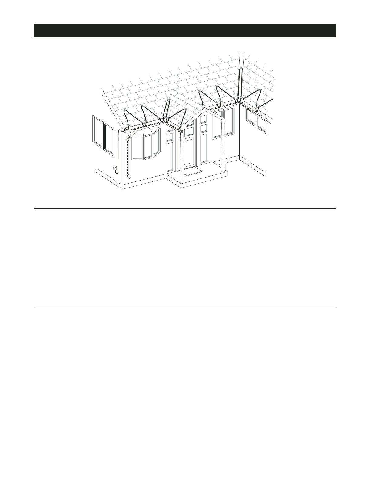
• For roofs without gutters, route the
heating cable as shown in Figure 7.
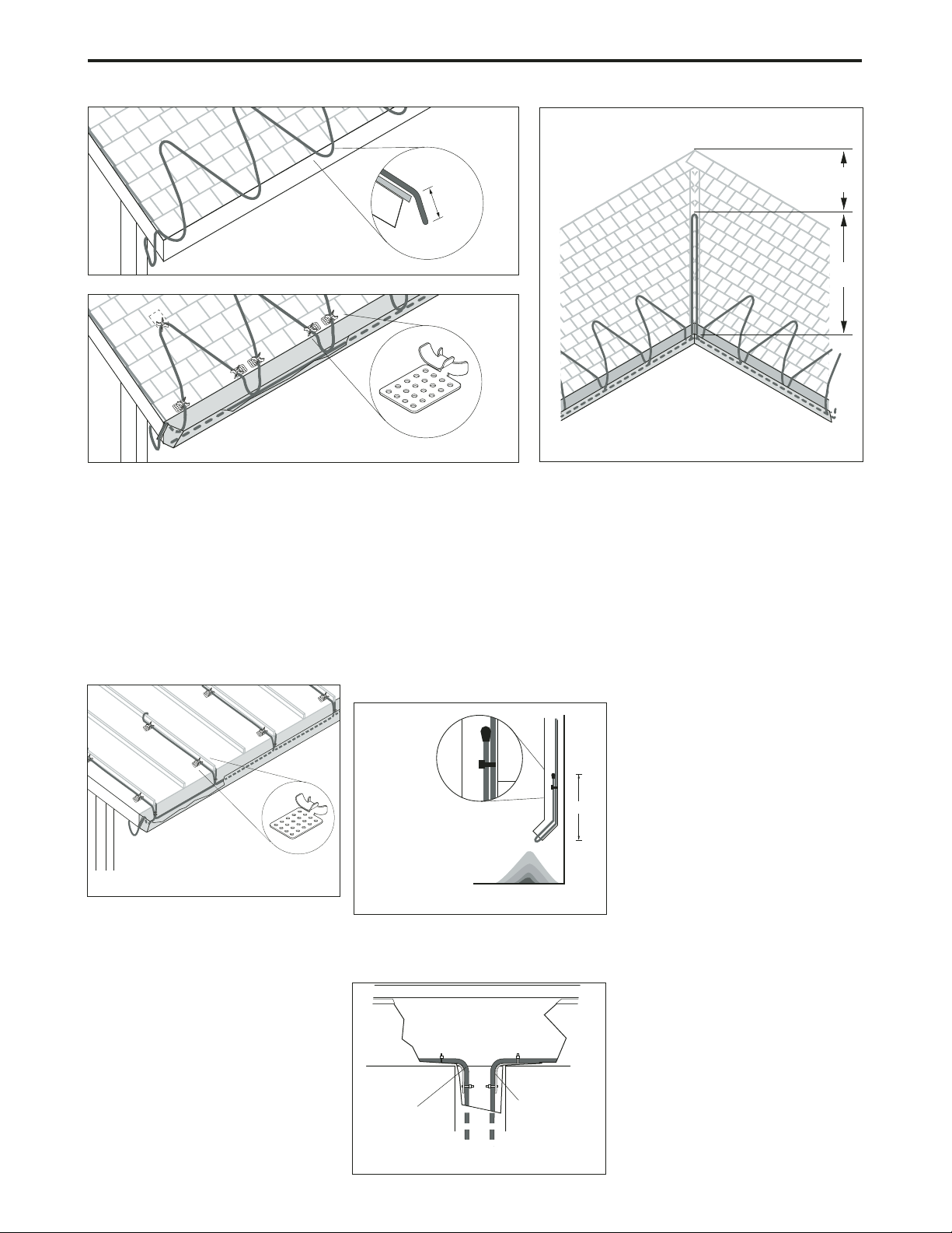
• Extend the top of each heating cable loop
beyond where the wall joins the roof.
• Trace two-thirds of the way up each valley
with a double run of heating cable as
shown in Figure 8.
• Use H913/H914 roof clips to route heating
cable into and out of the gutter in such a
way as to prevent abrasion to the cable.
Protect all cable that protrudes past the
lower opening of the downspout.
• One H913 kit contains ten roof clips for
approximately 7 linear feet of roof edge.
One H914 kit contains 50 roof clips for
approximately 35 linear feet of roof edge.
• Roof clips may be attached to a shake or
shingle roof with nails or screws as shown
in Figure 9. Roof clips may be attached to
a metal roof using screw, nail or adhesive
as shown in Figure 10. (See H56723
installation instruction for more details.)
Reseal the nail or screw holes if necessary
before installing heating cable in the clips.
• A barrier (snow fence) can be placed on the
roof above the heating cable. This prevents
damage to the cable and keeps the
installation from coming loose due to ice
slides. The heating cable can be attached to
the barrier with UV-resistant cable ties,
instead of using roof clips, if desired. Do not
use wire or other materials because they
may damage the heating cable.
In gutters and downspouts
• Run heating cable along gutters and into
downspouts, ending below the freezing level.
Permanent attachment of the cable to the
gutter bottom is not necessary. Loop the
heating cable in downspouts. Do not leave
the end of the Gardian in air at the end of
the downspout as shown in Figure 11.
• Use H915 Hanger Brackets at the
gutter/downspout transition to protect the
heating cable from fraying and from
damage from sharp edges and to provide
strain relief as shown in Figure 12. Refer
to the H915 kit instructions for installation
details.
• Route and secure cable to avoid possible
mechanical damage, such as from ladders,
etc.
3. Mark the installation.
Two labels indicating the presence of
electric de-icing and snow-melting
equipment on the premises are included
with the heating cable. One label must be
posted at the electrical outlet cover. The
other label must be posted at the fuse or
circuit breaker panel. The labels must be
clearly visible.
4.Check the installation.
• Prior to plugging in, check to be sure the
heating cable is free of mechanical damage
(cuts, clamps, etc.).
• Using a megohmmeter, test each circuit
according to the instructions in the
“Heating cable testing and maintenance”
section on next page.
5.Starting the system.
• Tyco Thermal Controls recommends that
the system be tested per the “Cable
testing and maintenance” section below.
• Plug the heating cable into a 120 V
ground-fault protected outlet.
• Check the circuit breaker to verify power
to the cable.
7
2"–3"
(5–8 cm)
Figure 7 Roofs without gutters
2/3
1/3
Figure 8 Valleys
Figure 9 Standard roof clip attachment
Figure 10 Standing seam roof clip
attachment
Accumulated ice
can be removed.
12"
Figure 11 Heating cable in downspout
Heating cable
Hanger bracket
Figure 12 Hanger brackets
8
Product specifications
W51-6P W51-12P W51-18P W51-24P W51-50P W51-75P W51-100P
Cable length (feet) 6 12 18 24 50 75 100
Min. power output at 40°F (5°C) on pipe (watts) 36 72 108 144 300 450 600
Nominal power output in ice and snow (watts) 48 96 144 192 400 600 800
General specifications for all W51 products
Nominal cable width (in) 0.42
Nominal cable thickness (in) 0.22
Heating cable bus wire gauge (AWG) 16
Cold lead length (in) 30
Voltage rating (V) 110–120
Plug rating (amps) 15
Circuit breaker sizing minimum (amps) 15
Max. exposure temperature 150°F (65°C)
Electrical classification Nonhazardous areas only
Exposure to chemicals None
© 2004 Tyco Thermal Controls LLC Printed in USA PN 556229 H54499 12/04
Worldwide Headquarters
Tyco Thermal Controls
300 Constitution Drive
Menlo Park, CA 94025-1164
USA
Tel (800) 545-6258
Fax (800) 527-5703
[email protected]
www.tycothermal.com
Important: All information, including illustrations, is believed to be reliable. Users, however, should
independently evaluate the suitability of each product for their particular application. Tyco Thermal
Controls makes no warranties as to the accuracy or completeness of the information, and disclaims any
liability regarding its use. Tyco Thermal Controls' only obligations are those in the Tyco Thermal
Controls Standard Terms and Conditions of Sale for this product, and in no case will Tyco Thermal
Controls or its distributors be liable for any incidental, indirect, or consequential damages arising
from the sale, resale, use, or misuse of the product. Specifications are subject to change without
notice. In addition, Tyco Thermal Controls reserves the right to make changes—without notification to
Buyer—to processing or materials that do not affect compliance with any applicable specification.
Tyco, Gardian and Raychem are trademarks or registered trademarks of Tyco Thermal Controls LLC
or its affiliates.
Canada
Tyco Thermal Controls
250 West St.
Trenton, Ontario
Canada K8V 5S2
Tel (800) 545-6258
Fax (800) 527-5703
Heating cable testing and maintenance
Make sure that gutter and downspouts are free
of leaves and other debris prior to the winter
season.
Using a 2500-Vdc megohmmeter (2500 Vdc
minimum), unplug the Gardian and test the
unit by checking the insulation resistance
between the flat blade and the ground pin in
the plug. Minimum reading should be 1000
megohms regardless of Gardian length.
Record the original values for each circuit.
Take additional readings during regularly
scheduled maintenance and compare to the
original value. If the readings fall below 1000
megohms, inspect heating cables and
insulation for signs of damage.
WARNING! Fire and shock hazard.
Damaged heating cable can cause electrical
shock, arcing, and fire. Do not attempt to
repair or energize damaged heating cable.
Remove it at once and replace with a
new length.

Other Raychem Cables And Connectors manuals

Raychem S-150-E User manual

Raychem

Raychem S-150-E User manual

Raychem TRACETEK TT3000 SERIES User manual

Raychem

Raychem TRACETEK TT3000 SERIES User manual

Raychem TRACETEK TT5000-HS User manual

Raychem

Raychem TRACETEK TT5000-HS User manual

Raychem nvent MI Series User manual

Raychem

Raychem nvent MI Series User manual

Raychem pyrotenax Alloy 825 User manual

Raychem

Raychem pyrotenax Alloy 825 User manual

Raychem IEK-25-04 User manual

Raychem

Raychem IEK-25-04 User manual

Raychem t-100 User manual

Raychem

Raychem t-100 User manual

Raychem E-150 User manual

Raychem

Raychem E-150 User manual

Raychem FTC-XC User manual

Raychem

Raychem FTC-XC User manual

Raychem C25-100 User manual

Raychem

Raychem C25-100 User manual

Raychem JBM-100-E User manual

Raychem

Raychem JBM-100-E User manual

Raychem TraceTek TT3000 SERIES User manual

Raychem

Raychem TraceTek TT3000 SERIES User manual

Raychem JBS-100-EP User manual

Raychem

Raychem JBS-100-EP User manual

Raychem RayClic-PC User manual

Raychem

Raychem RayClic-PC User manual

Raychem FROSTGUARD User manual

Raychem

Raychem FROSTGUARD User manual

Popular Cables And Connectors manuals by other brands

Goobay 51767 user manual

Goobay

Goobay 51767 user manual

Eneo VCQ-6057 Operating instructions manual

Eneo

Eneo VCQ-6057 Operating instructions manual

Omron XN2 quick start guide

Omron

Omron XN2 quick start guide

Sumitomo Lynx-CustomFit LYNX2-LC installation manual

Sumitomo

Sumitomo Lynx-CustomFit LYNX2-LC installation manual

hager XEVA240 installation manual

hager

hager XEVA240 installation manual

OMB TVS-TUNNEL/S quick start guide

OMB

OMB TVS-TUNNEL/S quick start guide

Philips SWV3040S Warranty

Philips

Philips SWV3040S Warranty

Medit i500 Maintenance and Storage Guide

Medit

Medit i500 Maintenance and Storage Guide

MacArtney OptoLink instructions

MacArtney

MacArtney OptoLink instructions

Leviton DMXSM-H18 user guide

Leviton

Leviton DMXSM-H18 user guide

NEUTRIK NL4FX Assembly instructions/use and care manual

NEUTRIK

NEUTRIK NL4FX Assembly instructions/use and care manual

Dynalink A 3135F operating instructions

Dynalink

Dynalink A 3135F operating instructions

SMC Networks KQB2-F Series Operation manual

SMC Networks

SMC Networks KQB2-F Series Operation manual

NORAUTO NO6773 manual

NORAUTO

NORAUTO NO6773 manual

KIFCO Water-Reel B110G Operator's manual

KIFCO

KIFCO Water-Reel B110G Operator's manual

HRS FH12 Series operating instructions

HRS

HRS FH12 Series operating instructions

Weidmüller BVFL 7.62HP Series Assembly instructions

Weidmüller

Weidmüller BVFL 7.62HP Series Assembly instructions

Rean RCAC3F-X-000 Assembly instruction

Rean

Rean RCAC3F-X-000 Assembly instruction

manuals.online logo
manuals.online logoBrands
  • About & Mission
  • Contact us
  • Privacy Policy
  • Terms and Conditions

Copyright 2025 Manuals.Online. All Rights Reserved.