Taramps Electronics MD3000.1 PREMIER User manual


01
•Custos de retirada e reinstalação do equipamento,
bem como seu transporte até o posto de assistência
técnica;
•Cartão de garantia não preenchido ou rasurado;
•Danos de qualquer natureza, consequentes de
problemas no produto, bem como perdas causadas
pela interrupção do uso._
•O produto apresentar danos decorrentes de quedas,
impactos ou da ação de agentes da natureza
(inundações, raios, etc.);
A TARAMPS, localizada à Rua Abílio Daguano, 274 Res.
Manoel Martins - Alfredo Marcondes - SP,
Em caso de defeito no período de garantia, a
responsabilidade da TARAMPS limita-se ao conserto
ou substituição do aparelho de sua fabricação.
Esta garantia exclui:
CEP 19.180-000, garante este produto contra defeitos
d e p r o j e t o, f a b r i c a ç ã o, m o n t a g e m e / o u
solidariamente em decorrência de vícios de projeto
que o torne impróprio ou inadequado ao uso a que se
destina, pelo prazo de 12 meses, a partir da data de
aquisição.
•Produtos danificados por instalação incorreta,
infiltração de água, violação por pessoas não
autorizadas;
•Lacre de garantia rasurado ou rasgado;
•Casos onde o produto não seja utilizado em
condições normais;
•Defeitos provocados por acessórios, modificações ou
equipamentos acoplados ao produto;
•Cases in which the product is not used in adequate
conditions;
•Damage of any kind, due to problems in the product, as
well as losses caused by discontinued use of the product.
This warranty excludes:
•Erasured or torn warranty seal;
•Costs involving uninstallation, reinstallation of
equipment as well as shipment to the factory;
•Damaged products by improper installation, water
infiltration, violation by unauthorized individuals;
12 months from the date of purchase. In case of defect
during the warranty period, TARAMPS responsibility is
limited to the repairing or substitution of the device of its
own making.
•Defects caused by accessories, modifications or features
attached to the product;
•The product with damage from falling, bumps or nature
related problems (flooding, lightning, etc.);
•Warranty card is not properly filled or torn;
TARAMPS, located on Abilio Daguano Street 274, Res.
Manoel Martins – Alfredo Marcondes, SP - Brazil, ZIP
CODE 19180-000, guarantees this product against any
defects on terms of project, making, assembling, and/or
with solidarity, due to project vices which cause it
improper or inadequate to its original use within
Índice / Index
TERMO DE GARANTIA / TERM OF WARRANTY
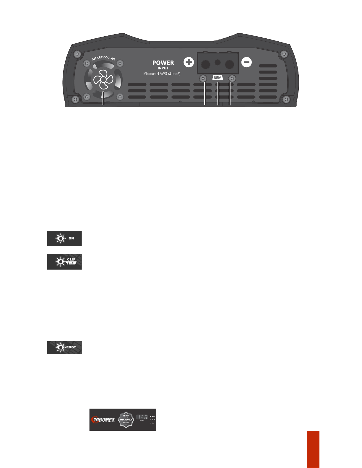
04 • Conector de alimentação
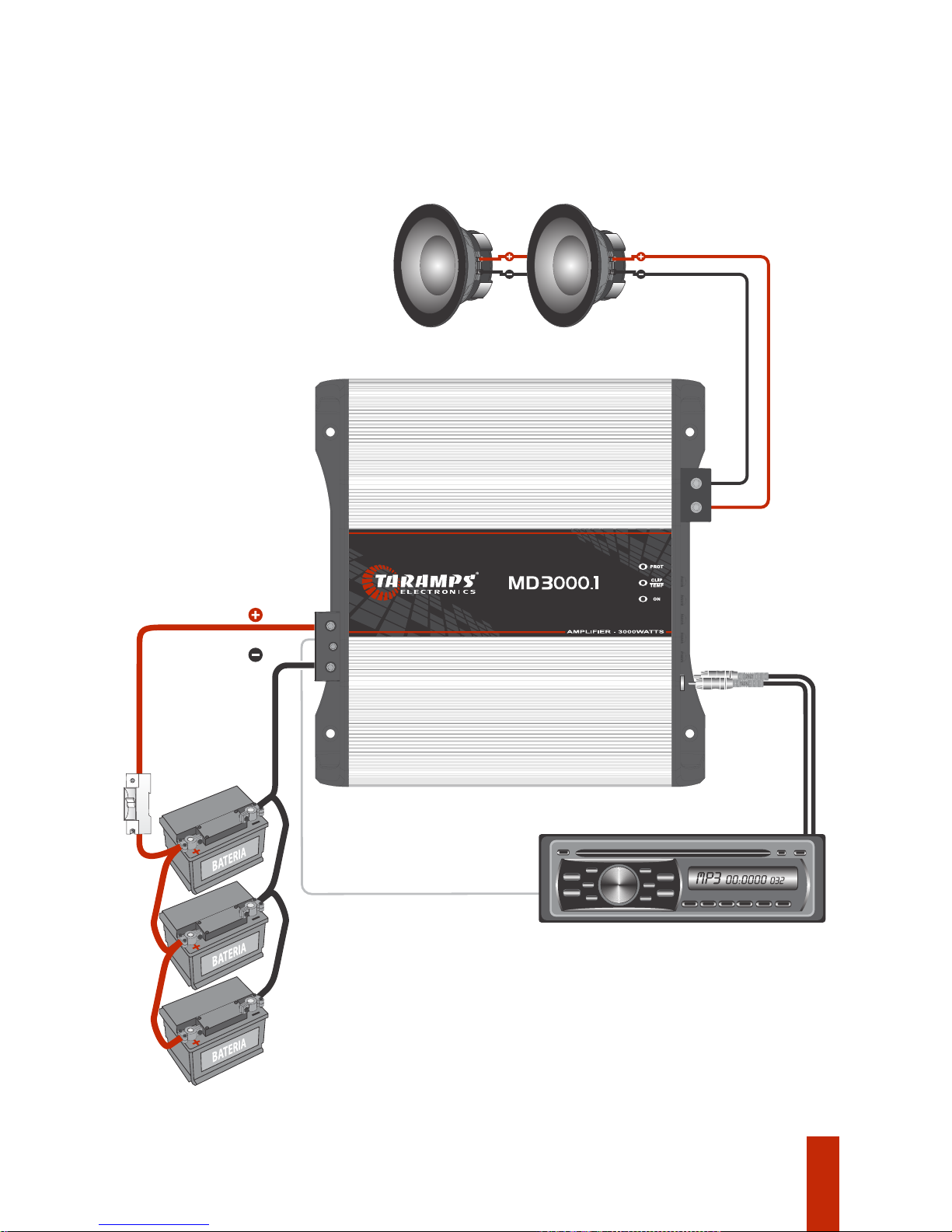
05 • Instalação
10 • Características técnicas
• Bitola de ação e fusível recomendados
• LEDs indicadores e sistema de proteção
01 • Termo de garantia
02 • Introdução
• Recomendações importantes
03 • Funções, entradas e saídas
05 • Installation
• Recommended wire gauge & fuse
•LEDs indicators & protection system
01 • Term of warranty
07 • Introduction
08 • Functions, inputs & outputs
• Key recommendations
10 • Technical features
09 • Power supply connector

02
Recomendações importantes
3 - É obrigatório a instalação de fusíveis para proteção em caso de sobrecarga. O fusível ou
disjuntor deve ser instalado o mais próximo possível da bateria, e ser dimensionado de
acordo com o amplificador;
7 - A instalação do mesmo deve ser feita por um profissional qualificado.
1 - Leia atentamente este manual de instruções antes de efetuar qualquer ligação;
2 - Observe atentamente a polaridade da fiação de alimentação (positivo e negativo da
bateria) e dos alto falantes, bem como a impedância mínima do amplificador;
6 - O cabo de sinal (RCA), deve passar separado da fiação original do veículo, ou de qualquer
outro cabo de alimentação, para evitar interferências;
4 - A bitola dos fios de alimentação é extremamente importante tanto para se obter a
potência desejada do amplificador, quanto para sua segurança. Siga a bitola do fio
recomendada neste manual (páginas 5/6). Bitolas menores que o especificado causam perda
de potência e sobreaquecimento dos cabos. É importante que os cabos de alimentação sejam
o mais curto possível;
Qualquer conexão na entrada ou saída do amplificador somente deverá ser feita com o
amplificador desligado;
5 - O amplificador deve ser instalado em um local firme, arejado e seco;
Para aproveitar ao máximo os recursos do seu amplificador, indicamos abaixo algumas
recomendações importantes:
Introdução
Parabéns pela compra de um produto Taramps.
Desenvolvido em moderno laboratório, com a mais alta tecnologia e profissionais altamente
qualificados.
Caso haja dúvida mesmo depois da leitura deste manual, entre em contato com nosso
suporte técnico pelo número de telefone 18-3266-4050 ou pelo nosso site
www.taramps.com.br.
Este manual explica todos os recursos, operações e orientações para solucionar dúvidas que
possam surgir em sua instalação. Reserve algum tempo para lê-lo atentamente e garantir
uma instalação adequada e o uso de todos os benefícios que este produto pode oferecer.
A Taramps reserva o direito de modicar o conteúdo deste manual sem aviso prévio e nem obrigatoriedade
de aplicar as modicações em unidades anteriormente produzidas.

03
FREQ.: Determina a frequência de atuação do Bass Boost de 35Hz a 55Hz.
BOOST: Reforço para os Sub-graves, com amplitude variável de 0 a +10dB.
FILTRO LOW PASS (LPF): Ajuste variável de 90Hz a 18KHz, que determina o fim da frequência de
operação do amplificador.
4 - BASS BOOST
Veja os exemplos abaixo:
3 - CROSSOVER
FILTRO HIGH PASS (HPF): Ajuste variável de 10Hz a 90Hz, que determina o início da frequência de
operação do amplificador.
Para associações de alto-falantes, a impedância a ser considerada é a impedância resultante.
2 - LEVEL: Ajusta a sensibilidade de entrada do amplificador, o que permite um perfeito ajuste aos níveis
de sinal de saída de praticamente todos os modelos de CD/DVD Player do mercado.
1 - INPUT (R e L): Entradas dos sinais a serem amplificados. Conectar as mesmas às saídas RCA do CD /
DVD Player, utilizando cabos blindados de boa qualidade para evitar a captação de ruídos.
6 - SPEAKER: Saída (positivo e negativo) para a conexão dos transdutores (alto-falantes). Seguir a
polaridade indicada e a impedância mínima recomendada.
5 - MONITOR: Conexão para acessório que tem como função o monitoramento do amplificador, onde
todas as informações dos LEDs indicadores, como distorção (CLIP/TEMP) e acionamento da proteção
(PROT), serão mostradas simultaneamente. (Acessório incluso somente no modelo PREMIER).
Funções, entradas e saídas
4 OHMS 4 OHMS
Amplificador 2 OHMS
Impedância
resultante:
2 OHMS
8 OHMS 8 OHMS
Amplificador 4 OHMS
Impedância
resultante:
4 OHMS
2 OHMS 2 OHMS
Amplificador 1 OHM
Impedância
resultante:
1 OHM
SPEAKER
INPUT
MONITOR
MAX .
LEVEL
0
BASS BOOST
BOOST
+100
dB
FREQ.
55
35
Hz
Hz
LOW PASS
9010
CROSSOVER
HIGH PASS
18K Hz90
1 2 3456

04
POWER
INPUT
Minimum 4 AWG (21mm²)
1 2 3 4
Conector de alimentação
4 - TERMINAL DE ALIMENTAÇÃO NEGATIVO: Deverá ser usado cabo de 21mm² o mais curto possível, ligado
ao polo negativo da bateria.
1 - COOLER: Este amplificador possui um cooler de ventilação interna, e que não podem ser obstruídos. Para
perfeito funcionamento, o amplificador deve ser instalado em local seco e arejado. Recomendamos não embutir
o mesmo, para que assim o ar circule em toda a extensão interna do produto, assim evitando a atuação da
proteção térmica.
2 - TERMINAL DE ALIMENTAÇÃO POSITIVO: Usar cabo 21mm² direto do terminal positivo da bateria com
fusível ou disjuntor (150A) o mais próximo possível da mesma.
3 - TERMINAL REMOTE: deve ser ligado a saída remote do CD/DVD Player por meio de um cabo de 0,75mm².
Recomendamos que todo os cabos tenham as pontas estanhadas, para melhor contato elétrico.
LEDs indicadores e sistemas de proteção
LED azul aceso contínuo:
Indica que o amplificador está ligado.
LED amarelo piscando: Temperatura excessiva (Pode ser causada por obstruções dos coolers
internos, instalação inadequada ou em local mal ventilado).
Quando o amplificador chegar a temperatura de aproximadamente 80°C a proteção térmica
atua, o áudio é interrompido e o LED amarelo começará a piscar. O cooler ficará ligado para
resfriar os componentes rapidamente. Somente quando o amplificador chegar a uma
temperatura segura, o áudio é liberado e o amplificador voltará ao normal.
Recomendamos não desligar o amplificador, para que o tempo de resfriamento seja
menor, através das ventilações dos coolers.
LED amarelo piscando de acordo com a música: Indica que o amplificador está operando no
limiar da distorção. Caso o led vermelho também piscar, indica distorção excessiva.
LED vermelho aceso contínuo:
Foi detectado curto-circuito ou impedância inferior a suportada na saída.
LED vermelho pisca 2x:
Voltagem de alimentação inferior a 9V.
LED vermelho pisca 3x:
Voltagem de alimentação superior a 16V.
NOTA: Somente o amplificador MD 3000.1 PREMIER possui o voltímetro na parte superior do
adesivo.

05
Qualquer ligação nos conectores de alimentação, entrada ou saída deverão ser feitas
somente com o amplificador desligado.
Instalação
Installation
Atenção: O uso de fiação com bitola inferior ao recomendado causa perda de potência e
sobreaquecimento da fiação.
Observe a polaridade, nunca inverta os cabos de alimentação, sob risco de danos ao
amplificador.
Cabo de alimentação positivo / negativo_______________________________ 21mm²
Bitolas dos cabos de saída ____________________________________________ 6mm²
Fusível ou disjuntor de proteção________________________________________ 150A
Bitola do cabo remote ____________________________________________ 0,75mm²
É obrigatório a instalação de fusíveis ou disjuntores de proteção o mais próximo da(s)
bateria(s).
Calculado considerando um comprimento máximo de 4m. Distancia maiores que
esta, será preciso aumentar as bitolas dos cabos.
It is compulsory to install a protection fuses or circuit breakers as close as possible from
batteries.
Calculated considering a maximum length of 4m. Distance greater than this, you will
need to increase the cable gauges.
Remote cable ____________________________________________________ 18 AWG
Positive / negative power supply cable __________________________________4 AWG
Caution: Using wire gauges below the recommendation will result in power loss and
overheating of wiring.
Output cables with gauge____________________________________________9 AWG
Check polarity and never reverse power supply cables due to the risk of damage to the
amplifier.
Protection fuse or circuit breaker_______________________________________ 150A
Bitola de fiação e fusível recomendados
Recommended wire gauge and fuse
CAUTION: All connections to power supply, input and output connectors must be
carried out only with amplifier off.

*Imagens Ilustrativas / Illustrative images
6mm² (9 AWG)
6mm² (9 AWG)
06
OBS: Em caso de drivers e tweeters é indispensável a instalação de filtro
passivo nos terminais positivo dos mesmos (Consulte manual do fabricante).
Note: In case of horns and tweeters you must install a passive filter in the
positive terminal of the same ones (Consult transducer’s manufacturer
manual).
CD/DVD Player / Head Unit
Cabo RCA / RCA Cable
Taramps
21mm² (4 AWG)
12V
GND
21mm² (4 AWG)
DISJUNTOR
Instalação / Installation
Cabo Remote 0,75mm² / Remote Cable 18 AWG
Examples of connections in the power supply input:
Note: Required battery bank capacity:
Exemplos de conexões na entrada de alimentação:
Obs: Capacidade requerida do banco de baterias: Mínimo 150Ah
At least 150Ah

07
Key recommendations
Introduction
3 - It is compulsory to install fuses to protect against overloading. The fuse or circuit breaker
must be installed as close as possible to the battery and sized up according to the amplifier;
7 - The amplifier must be installed by a qualified professional.
6 - In order to avoid interferences, the signal cable (RCA) must be away from the original
wiring of vehicle or from any other power supply cable;
Any connection to the amplifier input or output must be carried out when amplifier is
off;
2 - Check carefully the polarity of power supply wiring (battery's positive and negative
terminals) loudspeakers and the minimum speaker impedance;
You can find below some key recommendations to get the most out of your amplifier:
5 - Amplifier must be installed in a firm and ventilated area;
4 - The gauge of power supply wiring is extremely important both to reach the desired
amplifier output and to the amplifier's safety. Use the wire gauge recommended in this
manual (pages 5/6). Using wire gauges below the specified value will result in power loss and
overheating of cables. It is important that the power supply cables are the shortest possible;
1- Read this instruction manual carefully before carrying out any connection;
Taramps reserves the right to modify the contents of this document at any time without prior notice and does
not have the obligation to apply the changes in units which were previously produced.
Congratulations on your purchase of a Taramps product.
For questions, please call +55 (18) 3266-4050, e-mail [email protected] or visit
www.taramps.com.br.
This manual covers all features, operations and instructions to solve any doubt that may arise
during the installation. Please take some time to read it carefully in order to ensure the proper
installation and the use of all benefits that this product can offer.
It was developed in a modern laboratory and with the latest technology.

08
SPEAKER
INPUT
MONITOR
MAX .
LEVEL
0
BASS BOOST
BOOST
+100
dB
FREQ.
55
35
Hz
Hz
LOW PASS
9010
CROSSOVER
HIGH PASS
18K Hz90
1 2 3456
Functions, inputs & outputs
1 - INPUT (R and L): Inputs of signals to be amplified. Connect these signals to RCA outputs of Head Unit ,
using good quality shielded cables to avoid noise influence.
2 - LEVEL: It sets the amplifier input sensitivity, which allows an optimal adjustment to the output signals
levels of nearly all models of Head Unit found in the market.
FREQ.: Set the Bass Boost center frequency, from 35Hz up to 55Hz.
6 - SPEAKER: Output (positive and negative) to transducers connection (speakers). Follow the polarity
described and the minimum impedance recommended.
3 - CROSSOVER
HIGH PASS: Variable adjustment from 10Hz to 90Hz, which determines the beginning of the amplifier
operating frequency.
LOW PASS: Variable adjustment from 90Hz to 18KHz, which determines the end of the amplifier
operating frequency.
BOOST: Boost for bass levels in 50Hz, with variable gain up 0 to +10dB.
4 - BASS BOOST
5 - MONITOR: Connection to an accessory, which function is to monitor the amplifier and it is where
all information from the indicator LEDs, such as distortion (CLIP/TEMP) and protection actuation
(PROT), will be displayed simultaneously. (Accessory included in PREMIER model only).
To combine speakers, the resulting impedance must be taken into consideration.
See the examples below:
4 OHMS 4 OHMS
Resulting
impedance:
2 OHMS
Amplifier 2 OHMS
8 OHMS 8 OHMS
Resulting
impedance:
4 OHMS
Amplifier 4 OHMS
2 OHMS 2 OHMS
Resulting
impedance:
1 OHM
Amplifier 1 OHM

09
Power supply connector
3 - REMOTE TERMINAL: The remote Head Unit output must be connected by a 0,75mm² (18 AWG) cable.
It is recommended that all cables must have tinned ends to improve electrical contact.
1 - FAN: This amplifier has one internal ventilation fan, and cannot be blocked. For perfect functioning, the
amplifier must be installed in a cool and aired place. It is recommended not to embed it, so that the air circulates
throughout the inside of the product extension, thereby preventing the thermal protection from acting.
2 - POSITIVE POWER SUPPLY TERMINAL: Use a 4 AWG (21mm²) cable directly from the positive battery
terminal with fuse (150A), as close as possible from the battery.
4 - NEGATIVE POWER SUPPLY TERMINAL: A 4 AWG (21mm²) cable as short as possible must be used,
connected to the negative battery pole.
NOTE: Only the MD 3000.1 PREMIER amplifier has the voltmeter at the top of the sticker.
RED LED flashes 3x:
When the amplifier reaches the temperature of approximately 80°C (176°F), the thermal
protection starts working, the audio is interrupted and the yellow LED will start flashing. The fans
will be functioning, in order to cool down the components quickly. Only when the amplifier
reaches a safe temperature level, the audio is released and the amplifier gets back to its normal
functioning.
Power supply voltage greater than 16V.
We recommend don’t turn off the amplifier, so that the cooling time will be shorter, through
the ventilation of fans.
RED LED flashes 2x:
Blue LED steady on:
Indicates that the amplifier is turned on.
Flashing yellow LED: Excessive temperature (May be caused by obstruction of the internal fans,
improper installation or poorly ventilated location).
Blinking yellow LED according to music: Indicates that the amplifier is operating at the
threshold of distortion. If the red LED also blinks, it indicates excessive distortion.
Short-circuit or impedance lower than that supported at output.
Red LED steady on:
Supply voltage less than 9V.
LEDS indicators & protection system
POWER
INPUT
Minimum 4 AWG (21mm²)
1 2 3 4

10
Minimum Output Impedance:
Impedância Mínima de Saída
Sensibilidade de Entrada
Potência Nominal - Output Power / @12.6VDC
1 OHM:
Eciência
Dimensões (L x A x P)
Number of Channels:
Número de Canais
Signal- to-noise Ratio:
LPF (Filtro Passa Baixa)
Freq.:
Tensão de Alimentação Máxima
Relação Sinal-Ruído
HPF (Filtro Passa Alta)
Consumo na Potência Nominal
Input Sensitivity (Level 100%):
(High Pass Filter):
Impedância de Entrada
2 OHMS:
8 OHMS:
Frequency Response (Full Range):
(Low Pass Filter):
Efficiency:
4 OHMS:
Resposta de Frequência
Crossover
Sistema de Proteção
Boost:
Protection System:
Tensão de Alimentação Mínima
Minimum Supply Voltage:
Maximum Supply Voltage:
Input Impedance:
Idle Consumption:
Consumo Musical
Consumo em Repouso
Musical Consumption / @12.6VDC:
Rated Power Consumption:
Dimensions (W x H x L):
Peso
Weigth:
Características técnicas / Technical features
**Frequency response measured at 2 times the minimum impedance.
*Potência nominal com sinal senoidal de 60Hz a 1KHz e THD <= 1% na saída, utilizando carga resistiva na impedância mínima, medida com analisador de áudio Audio
Precision APx525 ou equipamento com performance e precisão equivalente, com o produto a uma temperatura máxima de 50°C e voltagem de alimentação a 12,6V.
Os valores citados são típicos e podem sofrer pequenas variações devido a tolerância de componentes ou do processo de fabricação.
**Resposta em frequência medida no dobro da impedância mínima.
*Rated power with 60Hz to 1KHz sinusoidal signal and THD <= 1%, with resistive
loads, measured with Audio Precision APx525 audio analyzer or equivalent and the
product at lower than 50°C case temperature and 12.6V supply voltage.
The values as above are typical and may vary, due to electronic components
tolerance or manufacturing process.
Para maiores informações ou dúvidas acesse nosso site ou entre em contato com o suporte da TARAMPS ELECTRONICS.
For further informations or questions, visit our website or contact TARAMPS
ELECTRONICS support.
Bass Boost:
1 Ohm 2 Ohms 4Ohms
1920W RMS 3000W RMS ---------------
--------------- 1920W RMS 3000W RMS
3000W RMS --------------- ---------------
10Hz ~ 18KHz (-3dB)**
79% 82% 85%
220mV
01
--------------- --------------- 1920W RMS
>90dB
10Hz ~ 90Hz (-12dB/8ª) Variável / Variable
90Hz ~ 18KHz (-12dB/8ª) Variável / Variable
35Hz ~ 55Hz
0 ~10dB (50Hz)
22K Ohms
Curto na Saída, curto na saída em relação ao GND, proteção de baixa
impedância, proteção de tensão baixa/alta e proteção térmica.
Short-Circuit to Output, Short on output compared to GND,
Low impedance at output, low/high supply voltage and
Thermal protection
9VDC
(8.98" x 2.76" x 8.58")
300A 290A 277.7A
150A 145A 138.8A
228 x 70 x 218mm
16VDC
2.5Kg (5.5lb)
1.00A 1.50A 1.20A
fc=18K

MN_510007260_R00
Table of contents
Languages:
Other Taramps Electronics Amplifier manuals

Taramps Electronics
Taramps Electronics HV40.000 User manual

Taramps Electronics
Taramps Electronics MD 250.1 User manual

Taramps Electronics
Taramps Electronics DSI200X4 User manual

Taramps Electronics
Taramps Electronics MD1200.1 User manual

Taramps Electronics
Taramps Electronics BASS 3K User manual

Taramps Electronics
Taramps Electronics BASS 20K User manual

Taramps Electronics
Taramps Electronics DS 300X4 User manual

Taramps Electronics
Taramps Electronics 3000 Trio Series User manual

Taramps Electronics
Taramps Electronics HV 20.000 User manual

Taramps Electronics
Taramps Electronics DS440X4 User manual