Taramps Electronics DS800X3 User manual

1 OHM
2 OHMS
2 x 200W RMS
+ 1 x 400W RMS

Índice / Index
01
• Sistema de proteção
05 • Instalação
• Bitola de ação e fusível recomendados
• Recomendações importantes
04 • Conector de saída e alimentação
• LED indicador
10 • Características técnicas
01 • Termo de garantia
03 • Funções e entradas
02 • Introdução
01 • Term of warranty
• Recommended wire gauge & fuse
07 • Introduction
• Key recommendations
05 • Installation
08 • Functions & inputs
• LED indicator
09 • Output & power supply connector
• Protection System
10 • Technical features
•Casos onde o produto não seja utilizado em
condições normais;
A TARAMPS, localizada à Rua Abílio Daguano, 274
Res. Manoel Martins - Alfredo Marcondes - SP,
CEP 19.180-000, garante este produto contra
defeitos de projeto, fabricação, montagem e/ou
solidariamente em decorrência de vícios de
projeto que o torne impróprio ou inadequado ao
uso a que se destina, pelo prazo de 12 meses, a
partir da data de aquisição.
Em caso de defeito no período de garantia, a
responsabilidade da TARAMPS limita-se ao
conserto ou substituição do aparelho de sua
fabricação.
• Produtos danificados por instalação incorreta,
infiltração de água, violação por pessoas não
autorizadas;
Esta garantia exclui:
• Lacre de garantia rasurado ou rasgado;
• D ef e i t o s p r o v o c a d o s p o r a c e s s ó r i o s ,
modificações ou equipamentos acoplados ao
produto;
•Danos de qualquer natureza, consequentes de
problemas no produto, bem como perdas
causadas pela interrupção do uso._
•Cartão de garantia não preenchido ou rasurado;
•O produto apresentar danos decorrentes de
quedas, impactos ou da ação de agentes da
natureza (inundações, raios, etc.);
• C u s to s d e re ti ra da e re i ns ta la çã o d o
equipamento, bem como seu transporte até o
posto de assistência técnica;
This warranty excludes:
12 months from the date of purchase. In case of
defect during the warranty period, TARAMPS
responsibility is limited to the repairing or
substitution of the device of its own making.
•Warranty card is not properly filled or torn;
•Damaged products by improper installation,
water infiltration, violation by unauthorized
individuals;
•Damage of any kind, due to problems in the
product, as well as losses caused by discontinued
use of the product.
•Erasured or torn warranty seal;
TARAMPS, located on Abilio Daguano Street 274,
Res. Manoel Martins – Alfredo Marcondes, SP -
Brazil, ZIP CODE 19180-000, guarantees this
product against any defects on terms of project,
making, assembling, and/or with solidarity, due to
project vices which cause it improper or
inadequate to its original use within
•Defects caused by accessories, modifications or
features attached to the product;
•The product with damage from falling, bumps or
nature related problems (flooding, lightning, etc.);
•Costs involving uninstallation, reinstallation of
equipment as well as shipment to the factory;
•Cases in which the product is not used in
adequate conditions;
Termo de garantia / Term of warranty

02
Recomendações importantes
2 - Observe atentamente a polaridade da fiação de alimentação (positivo e negativo da
bateria) e dos alto falantes, bem como a impedância mínima do amplificador;
4 - A bitola dos fios de alimentação é extremamente importante tanto para se obter a
potência desejada do amplificador, quanto para sua segurança. Siga a bitola do fio
recomendada neste manual (página 05/06). Bitolas menores que o especificado causam
perda de potência e sobreaquecimento dos cabos. É importante que os cabos de alimentação
sejam o mais curto possível;
Para aproveitar ao máximo os recursos do seu amplificador, indicamos abaixo algumas
recomendações importantes:
Qualquer conexão na entrada ou saída do amplificador somente deverá ser feita com o
amplificador desligado;
3 - É obrigatório a instalação de fusíveis para proteção em caso de sobrecarga. O fusível ou
disjuntor deve ser instalado o mais próximo possível da bateria, e ser dimensionado de
acordo com o amplificador;
5 - O amplificador deve ser instalado em um local firme, arejado e seco;
1 - Leia atentamente este manual de instruções antes de efetuar qualquer ligação;
6 - O cabo de sinal (RCA), deve passar separado da fiação original do veículo, ou de qualquer
outro cabo de alimentação, para evitar interferências;
7 - A instalação do mesmo deve ser feita por um profissional qualificado.
Introdução
Parabéns pela compra de um produto Taramps.
Desenvolvido em moderno laboratório, com a mais alta tecnologia e profissionais altamente
qualificados.
Este manual explica todos os recursos, operações e orientações para solucionar dúvidas que
possam surgir em sua instalação. Reserve algum tempo para lê-lo atentamente e garantir
uma instalação adequada e o uso de todos os benefícios que este produto pode oferecer.
Caso haja dúvida mesmo depois da leitura deste manual, entre em contato com nosso
suporte técnico pelo número de telefone 18-3266-4050 ou pelo nosso site
www.taramps.com.br.
A Taramps reserva o direito de modicar o conteúdo deste manual sem aviso prévio e nem obrigatoriedade
de aplicar as modicações em unidades anteriormente produzidas.

LED indicador
Funções e entradas
R
100Hz 700Hz
OFF
L
INPUT LPF
HIGH INPUT
AUTOMATIC REMOTE
LEVEL
CH1 / CH2 BASS
BOOST
0MAX. 010dB
CH3
L+R
L R
L R
23
1 4 5
Para o amplificador permanecer ligado, é necessário um volume mínimo, em torno de 2 a 5 (podendo
variar de acordo com a música ou modelo do CD / DVD Player). Note que caso o CD / DVD player seja ligado
com volume = 0, o amplificador não ligará.
Na ausência do áudio ou ao desligar o CD / DVD Player, o amplificador ainda permanecerá ligado por cerca de 30
segundos.
2 - INPUT L / R (RCA): Entradas dos sinais a serem amplificados. Conectar as mesmas às saídas RCA do CD / DVD
Player, utilizando cabos blindados de boa qualidade para evitar a captação de ruídos.
4 - BASS BOOST: Reforço para os Sub-graves em 50Hz, com amplitude variável de 0 a 10 dB, no canal CH3 .
3 - LEVEL CH1 / CH2: Ajusta a sensibilidade de entrada do CH1/CH2 do amplificador, o que permite um perfeito
ajuste aos níveis de sinal de saída de praticamente todos os modelos de CD / DVD Player do mercado.
1 - HIGH INPUT L / R (FIO): Entradas dos sinais a serem amplificados. Conectar as mesmas às saídas amplificadas
(FIOS) do CD / DVD Player.
Obs: Usando esta entrada, não será preciso conectar o cabo REMOTE, pois este amplificador possui um sistema
que reconhece a presença do áudio e liga automaticamente.
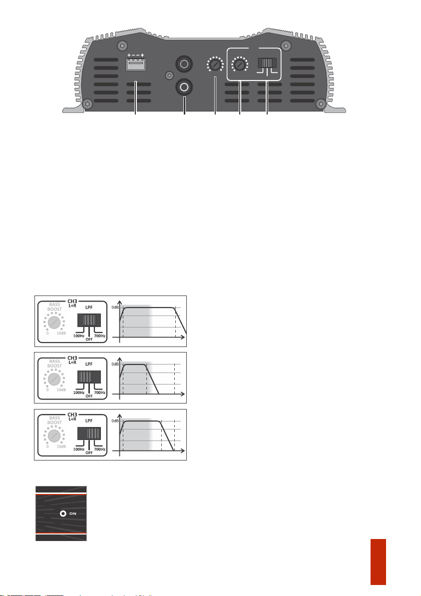
5 - CH3 L+R: Configurações do canal 3, resultante da soma de L+R do amplificador:
SELETOR NA POSIÇÃO - OFF
O canal CH3 irá responder a toda faixa de áudio (10Hz ~
25Khz). Normalmente utilizamos esta função quando temos
no sistema um crossover externo.
O canal CH3 amplifica somente os graves e subgraves. A
resposta se limita a 100Hz(-12dB/8ª), corte ideal para
subwoofers.
O canal CH3 amplifica os canais de áudio limitando a
resposta em 700Hz(-12dB/8ª), corte indicado para caixas tipo
‘‘TRIO’’ (Uso para som externo).
SELETOR NA POSIÇÃO - LPF 100Hz
SELETOR NA POSIÇÃO - LPF 700Hz
25KHz
700Hz
Faixa de áudio
10Hz
25KHz
100Hz
Faixa de áudio
10Hz
Faixa de áudio
10Hz 25KHz
ON: Aceso indica que o amplificador está ligado.
03
Conector de saída e alimentação
04
Proteção contra sobrecarga na saída: Corta o sinal de áudio caso seja detectado um curto
circuito ou impedância inferior à suportada na saída.
Sistema de proteção
Veja os exemplos abaixo:
3 - POWER (Conector de Alimentação): O terminal (+) do conector, deve ser ligado ao polo
positivo da bateria através de um cabo de bitola mínima de 10mm². O terminal (-) do conector
deve ser ligado adequadamente no polo negativo da bateria por meio de um cabo de bitola
equivalente ao cabo positivo. O terminal remote deve ser ligado á saída REMOTE do CD/DVD
Player, por meio de um cabo de 0,75mm².
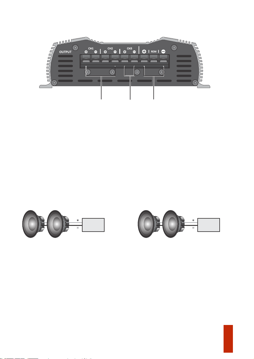
1 - OUTPUT : Para conectar o(s) alto falante(s). Seguir a polaridade indicada e a CH1 / CH2
impedância mínima recomendada. (Veja impedância no adesivo superior do amplificador).
O canal CH1 é associado a entrada L.
O canal CH2 é associado a entrada R.
Os canais CH1 e CH2 possuem filtro ativo HPF de 100Hz (-12dB/8ª).
2 - OUTPUT CH3: Para conectar o(s) alto falante(s). Seguir a polaridade indicada e a
impedância mínima recomendada. (Veja impedância no adesivo superior do amplificador).
O canal CH3 é a soma das entradas L e R.
Para associações de alto falantes, a impedância a ser considerada é a impedância resultante.
2 OHMS 2 OHMS
Para o amplificador em 1 ohm
Impedância
resultante:
1 OHM
4 OHMS 4 OHMS
Para o amplificador em 2 ohms
Impedância
resultante:
2 OHMS
POWER
L+R
LR
1
23

CAUTION: All connections to power supply, input and output connectors must be
carried out only with amplifier off.
It is compulsory to install protection fuses or circuit breakers as close as possible from
batteries.
Installation
Qualquer ligação nos conectores de alimentação, entrada ou saída deverão ser feitas
somente com o amplificador desligado.
Instalação
Observe a polaridade, nunca inverta os cabos de alimentação, sob risco de danos ao
amplificador.
Cabo de alimentação positivo / negativo_______________________________10mm²
É obrigatório a instalação de fusíveis ou disjuntores de proteção o mais próximo da(s)
bateria(s).
Calculado considerando um comprimento máximo de 4m. Distancia maiores que esta,
será preciso aumentar as bitolas dos cabos.
Bitola do cabo remote ____________________________________________ 0,75mm²
Fusível ou disjuntor de proteção_________________________________________60A
Bitolas dos cabos de saída __________________________________________ 1,5mm²
Atenção: O uso de fiação com bitola inferior ao recomendado causa perda de potência
e sobreaquecimento da fiação.
Bitola de fiação e fusível recomendados
Positive / negative power supply cable ___________________________________ 7 AWG
Caution: Using wire gauges below the recommendation will result in power loss and
overheating of wiring.
Output cables wire gauge____________________________________________15 AWG
Check polarity and never reverse power supply cables due to the risk of damage to the
amplifier.
Calculated considering a maximum length of 4m. Distance greater than this, you will need
to increase the cable gauges.
Protection fuse or circuit breaker__________________________________________ 60A
Remote cable ______________________________________________________18 AWG
Recommended wire gauge & fuse
05
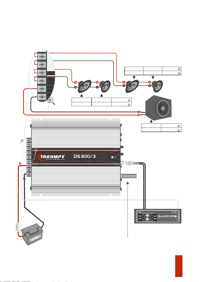
12V
GND
Cabo Remote 0,75mm² / Remote Cable 18 AWG
Cabo RCA / RCA Cable
Taramps
*Imagens Ilustrativas / Illustrative images
CD/DVD Player / Head Unit
Obs: Capacidade requerida do banco de
baterias: Mínimo 60Ah
At least 60Ah
Note: Required battery bank capacity: If you choose to use this input, you won’t need
to connect the RCA’S cable and remote signal.
Caso opte utilizar esta entrada, não será
necessário a conexão dos cabos RCA’s e nem o
cabo Remote.
Wire Input:
Entrada a Fio:
Note: In case of horns and tweeters you must install a passive filter in
the positive terminal of the same ones (Consult transducer’s
manufacturer manual).
OBS: Em caso de drivers e tweeters é indispensável a instalação de
filtro passivo nos terminais positivo dos mesmos (Consulte manual
do fabricante).
4 ohms
4 ohms
4 ohms
4 ohms
4 ohms
Subwoofer
Woofer
2 ohms
2 ohms
2 ohms
2 ohms
2 ohms
DS800X3 2
DS800X3 1
AMPLIFIER - 800WATTS. .
DS800X3 2
DS800X3 1
DS800X3 2
DS800X3 1
Instalação / Installation
06
DISJUNTOR
10mm² (7 AWG)
10mm² (7 AWG)

07
Key recommendations
Introduction
1- Read this instruction manual carefully before carrying out any connection;
You can find below some key recommendations to get the most out of your amplifier:
2 - Check carefully the polarity of power supply wiring (battery's positive and negative
terminals) loudspeakers and the minimum speaker impedance;
3 - It is compulsory to install fuses to protect against overloading. The fuse or circuit breaker
must be installed as close as possible to the battery and sized up according to the amplifier;
4 - The gauge of power supply wiring is extremely important both to reach the desired
amplifier output and to the amplifier's safety. Use the wire gauge recommended in this
manual (page 05/06). Using wire gauges below the specified value will result in power loss
and overheating of cables. It is important that the power supply cables are the shortest
possible;
5 - Amplifier must be installed in a firm and ventilated area;
6 - In order to avoid interferences, the signal cable (RCA) must be away from the original
wiring of vehicle or from any other power supply cable;
Any connection to the amplifier input or output must be carried out when amplifier is
off;
7 - The amplifier must be installed by a qualified professional.
Taramps reserves the right to modify the contents of this document at any time without prior notice and does
not have the obligation to apply the changes in units which were previously produced.
This manual covers all features, operations and instructions to solve any doubt that may arise
during the installation. Please take some time to read it carefully in order to ensure the proper
installation and the use of all benefits that this product can offer.
Congratulations on your purchase of a Taramps product.
It was developed in a modern laboratory and with the latest technology.
For questions, please call +55 (18) 3266-4050, e-mail suppor[email protected] or visit
www.taramps.com.br.
Functions & inputs
R
100Hz 700Hz
OFF
L
INPUT LPF
HIGH INPUT
AUTOMATIC REMOTE
LEVEL
CH1 / CH2 BASS
BOOST
0MAX. 010dB
CH3
L+R
L R
L R
23
1 4 5
25KHz
700Hz
Audio band
10Hz
25KHz
100Hz
Audio band
10Hz
Audio band
10Hz 25KHz
LED indicator
ON: Indicates that amplifier is on.
1- INPUT FOR SIGNALS L / R (HIGH LEVEL): Signal connectors to be amplified. Connect them to the hi-level
output connections (WIRES) from CD / DVD player.
In cause of absence of audio or turning CD player off, the amplifier will still remain on for around 30 seconds.
2 - INPUT L / R (RCA): Inputs of signals to be amplified. Connect these signals to RCA outputs of Head Unit, using
good quality shielded cables to avoid noise interference.
3 - LEVEL L / R: It sets the amplifier input sensitivity, which allows an optimal adjustment to the output signals
levels of nearly all models of Head Units found in the market.
4 - BASS BOOST: Boost for bass levels in 50Hz, with variable gain up to 10 dB for CH3 channel.
5 - CH3 L / R: Setup for CH3 channel, which is resulting from the L and R summing:
Attention: Using this connector, the connection of the REMOTE cable is isn’t required.
DS 800X3 has an audio recognition system which turn on the amplifier automatically.
In order to keep the amplifier ON, a minimum volume is required, around 2 to 5 (varying according to
song or CD player model). Notice that in case CD player is turned on with volume = 0, the amplifier won’t
turn on.
SELECTOR POSITION - OFF
The CH3 channel amplifiers the whole audio range,
responding from 10Hz ~ 25KHz. This function is normally
used when there is an external crossover in the system.
The CH3 channel amplifiers only bass signal, the response is
limited to 100Hz (-12dB/8ª), an optimal frequency cutoff for
subwoofers.
SELECTOR POSITION - LPF 700Hz
The CH3 channel amplifiers the audio signals, the response
is limited to 700Hz(-12dB/8ª), for use with three way box
(Outside the vehicle).
SELECTOR POSITION - LPF 100Hz
08
Both CH1 and CH2 has a fixed HPF filter 100Hz (-12dB/8 oct).
3 - POWER (Power Supply Connector): The connector terminal (+) must be connected to the
battery's positive pole with a 10mm² (minimum) wire gauge. The connector terminal (-) must
be properly connect to the battery's negative pole with a same wire gauge. The remote
terminal must be connected to the Head Unit REMOTE output with a 0.75mm² wire.
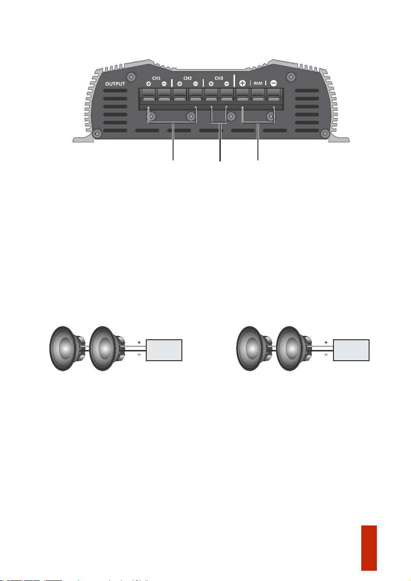
1 - OUTPUT CH1 / CH2: To connect the speaker(s). Follow the polarity and the minimum
impedance recommended. (See impedance on the top of the amplifier).
The CH3 is resulting from L and R sum.
To combine speakers, the resulting impedance must be taken in consideration.
The CH2 output comes from R input.
See the examples below:
The CH1 output comes from L input.
2 - OUTPUT CH3: To connect the speaker(s). Follow the polarity and the minimum impedance
recommended. (See impedance on top of the amplifier).
09
Output & power supply connector
Short-circuit Protection: Shutdown the amplifier when detect a short- circuit or impedance
lower than the supported at the output.
Protection system
2 OHMS 2 OHMS
For amplifier 1 ohm
Resulting
impedance:
1 OHM
4 OHMS 4 OHMS
For amplifier 2 ohms
Resulting
impedance:
2 OHMS
POWER
L+R
LR
1
23

Características técnicas / Technical features
10
Resposta de Frequência
Frequency Response:
Crossover (CH1 / CH2)
HPF (Filtro Passa Alta)
Minimum Output Impedance:
Signal- to-noise Ratio:
Number of Channels:
Sensibilidade de Entrada
Impedância Mínima de Saída
Input Sensitivity (Level 100%):
Potência Nominal
Número de Canais
Output Power / @12.6VDC:
Relação Sinal-Ruído
Idle Consumption:
Rated Power Consumption:
Musical Consumption / @12.6VDC:
Sistema de Proteção
Dimensões (L x A x P)
Tensão de Alimentação Mínima
Protection System:
Consumo na Potência Nominal
Dimensions (W x H x L):
Weigth:
Maximum Supply Voltage:
Consumo em Repouso
Minimum Supply Voltage:
Consumo Musical
Input Impedance:
Impedância de Entrada
Peso
Tensão de Alimentação Máxima
(High Pass Filter):
Crossover (CH3)
LPF (Filtro Passa Baixa)
(Low Pass Filter):
**Potência nominal com sinal senoidal de 60Hz e THD <= 1% no canal 3, utilizando carga resistiva, medida com analisador de áudio Audio
Precision APx525 ou equipamento com performance e precisão equivalente, com o produto a uma temperatura máxima de 50°C e voltagem de
alimentação a 12,6V. A impedância mínima do canal 3 deve ser sempre o dobro da impedância mínima dos canais 1 e 2.
***Frequency response measured at 2 times the minimum impedance.
***Resposta em frequência medida no dobro da impedância mínima.
Os valores citados são típicos e podem sofrer pequenas variações devido a tolerância de componentes ou do processo de fabricação.
**Rated power with 60Hz sinusoidal signal and THD <= 1% in CH3, with resistive load, measured with Audio Precision APx525 audio analyzer or
equivalent and the product at lower than 50°C case temperature and 12.6V supply voltage. The CH3 minimum impedance must be the double
of CH1 / CH2 minimum impedance.
The values as above are typical and may vary, due to electronic components tolerance or manufacturing process.
*Potência nominal com sinal senoidal de 1KHz e THD<=1% nos canais 1 e 2, utilizando carga resistiva na impedância mínima, medida com
analisador de áudio Audio Precision APx525 ou equipamento com performance e precisão equivalente, com o produto a uma temperatura
máxima de 50°C e voltagem de alimentação a 12,6V.
*Rated power with 1KHz sinusoidal signal and THD <= 1% in CH1 and CH2, at the minimum impedance resistive load, measured with Audio
Precision APx525 audio analyzer or equivalent and the product at lower than 50°C case temperature and 12.6V supply voltage.
102A
51A
1.0A
43A
1.4A
86A
03
CH1/CH2
250mV
10Hz ~ 25KHz (LPF = OFF)***
>88dB
10Hz ~ 100Hz (LPF = 100Hz)***
100Hz, 700Hz, OFF (-12dB/8ª)
10Hz ~ 700Hz (LPF = 700Hz)***
Selecionável / Selectable
10K Ohms (RCA) e 1K Ohms (Fio/Wire)
Sobrecarga na saída
Output overload
16VDC
100Hz (-12dB/8ª) Fixo / Fixed
100Hz ~ 25KHz (-3dB)***
CH3
9VDC
1.43Kg (3.15lb)
173 x 52 x 227mm (6.81" x 2.05" x 8.94")
CH3 (1 x 400W RMS) 2 OHMS**
CH1/ CH2 (2 x 200W RMS) 1 OHM*
1 OHM 2 OHMS
CH1/ CH2 (2 x 200W RMS) 2 OHMS*
CH3 (1 x 400W RMS) 4 OHMS**

Table of contents
Languages:
Other Taramps Electronics Amplifier manuals

Taramps Electronics
Taramps Electronics DS440X4 User manual

Taramps Electronics
Taramps Electronics TL-1500 User manual

Taramps Electronics
Taramps Electronics DSI200X4 User manual

Taramps Electronics
Taramps Electronics MD 250.1 User manual

Taramps Electronics
Taramps Electronics BASS 20K User manual

Taramps Electronics
Taramps Electronics HV 20.000 User manual

Taramps Electronics
Taramps Electronics DS 300X4 User manual

Taramps Electronics
Taramps Electronics 3000 Trio Series User manual

Taramps Electronics
Taramps Electronics MD1200.1 User manual

Taramps Electronics
Taramps Electronics HV40.000 User manual


