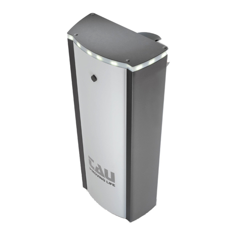
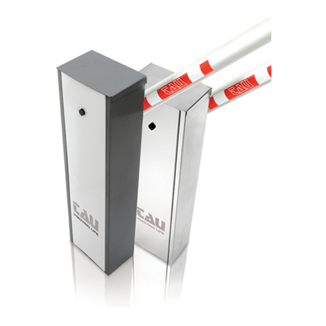
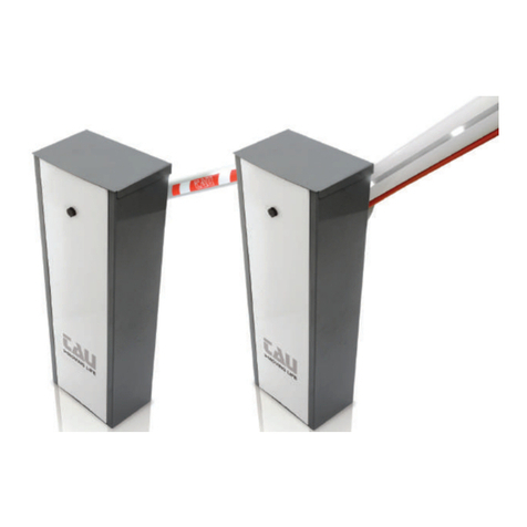
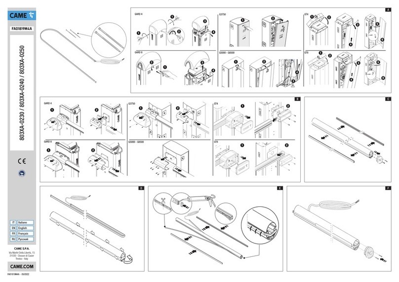
tau LUXE6KIT User manual

1
IT - Istruzioni originali
MANUALE D’USO E MANUTENZIONE
USE AND MAINTENANCE MANUAL
BEDIENUNGS - UND WARTUNGSANLEITUNG
MANUEL D’EMPLOI ET D’ENTRETIEN
MANUAL DE USO Y MANTENIMIENTO
LUXE
D-MNL0LUXE 07-02-2021 - Rev.17

2
15 - 20 mm
g.1 g. 2
g. 3
A
BC
80
159,194
R561
71,5°
78°
12
R15
223,4558
76,1001
440,3102
220,1551
R400,1159
98,1001
5,2°
190,423
5
447
1105
max. 6649
7096
228
339
945
111,562,742,3
L= Lunghezza totale dell’asta - Total lenght of the rod -
Die Gesamtlänge der Stange - Longeur totale de la tige -
Longitud total del asta - Comprimento total haste
7002
353L - 353
LUXE

3
A
180°
BC
1
g.4
LUXE
A

4
A C
B
=
=
=
=
180°
A
90°
B
30°
1
-
+
g.5
g. 7 g. 8
g.6
12
ATTENZIONE: la sezione dell’asta NON è simmetrica. Per lato attacco angia si intende quello di g. A,
per lato tappo quello di g. B).
WARNING: the bar section is NOT symmetrical. Flange connection side means the one in g. A, cap side
means the one in g. B).
ACHTUNG: Der Querschnitt der Stange ist NICHT symmetrisch. Die Seite des Flansch-Anschlusses ist
die auf Abb. A, die Seite der Abdeckung die auf Abb. B).
ATTENTION : la section de la tige N’EST PAS symétrique. Par côté raccord bride on entend celui de la
gure A, par côté bouchon celui de la gure B).
ATENCIÓN: la sección del asta NO es simétrica. Con lado de enganche brida se entiende aquel de la g.
A, con lado tapón aquel de la g. B).
ATENÇÃO: a secção da haste NÃO é simétrica. Como lado de encaixe ange quer-se dizer aquele da g.
A, como lado tampa aquele da g. B).
g. A g. B
LUXE

5
g. 9
g. 11
Led cable
Led cable
(Left hand
barrier)
AB
g. 10
1
3
1
1
1
2
4
3
5
6
8
11
12
7
9
9
9
9
10
8
2
LUXE

6
Guida alla scelta
e composizione
delle aste e degli
accessori
Guide to choose
and combine
booms and
accessories
Übersichtstabelle
-
Schrankenbäume
und Anbauteilen
Guide au choix et
à l’assortiment
des lisses et des
accessoires
Tablas de
Selección
Rápida – Astas y
accesorios
Guia para
escolher e
combinar hastes
e acessórios
+ 800GI +
800AE4
800AE5
800AE3
800AE3
800AE4 800AE3
800AE3
800AE2
4 m
5 m
5 m
6 m
7 m
+ 800GI +
+ 800GI +
+ 800RA +
+ 800RA +
+ 800RA +
+ 800FPL + 800PG
+ 800FPL + 800PG
Per lunghezze asta uguali o superiori a 5 m è obbligatorio l’uso dell’appoggio asta a terra sso o pensile.
For boom lengths equal or greater than 5 mt. it must use (mandatory) the ground boom support or the pendulum support
Bei einer Stangenlänge gleich oder über 5 m ist die Anwendung der Stangenauage am Boden fest oder hängend notwendig.
Pour lisses de 5 ou plus metrès de longueur, l’utilisation de la lyre de repos appui au sol ou suspendu est contraignante.
En el caso de que la longitud de la barra sea de 5 m o más, será obligatorio utilizar un soporte para la barra anclado al suelo o colgante.
Para comprimentos de haste iguais ou superiores a 5 m deve-se utilizar o suporte para haste xo no chão ou suspenso.
Per aste con passaggi utili superiori a 5 m è OBBLIGATORIO usare il rinforzo 800RA.
For bars with useful passage exceeding 5m, it is COMPULSORY to use the 800RA reinforcement.
Für Stangen mit Nenndurchlass über 5 m ist eine Verstärkung von 800RA UNBEDINGT notwendig.
Pour les barres de plus de 5 m d’envergure il est OBLIGATOIRE d’utiliser le renforcement 800RA.
Para varillas con pasaje útil superior a 5 m es OBLIGATORIO usar el refuerzo 800RA.
Para haste com largura de passagem útil superior a 5m é OBRIGATÓRIO aplicar o reforço 800RA.
ATTENZIONE: RISPETTO ALLA LUNGHEZZA NOMINALE DELL’ASTA, IL PASSAGGIO UTILE SI RIDUCE DI 353 mm (vedi g. 1).
ATTENTION: PASSAGE WIDTH EQUALS BAR LENGTH LESS 353 mm (see pic. #1).
ACHTUNG: TATSÄCHLICHE ABSPERRBREITE IST GLEICH BAUMLAENGE MINUS 353 mm (siehe Abb. 1).
AVERTISSEMENT: LE PASSAGE UTILE EST RÉDUIT DE 353 mm PAR RAPPORT À LA LONGUEUR NOMINALE DE LA LISSE (voir g. 1).
ATENCIÓN: EL PASO LIBRE ES IGUAL A LA LONGITUD DEL ASTA MENOS 353 mm (véase g. 1).
ATENÇÃO: A PASSAGEM UTIL É IGUAL AO CUMPRIMENTO DO HASTE MENOS 353 mm (ver g. 1).
MOLLA / SPRING / FEDER
RESSORT / MUELLE / MOLA
A) M-060MGREENL (ø 4,2 mm)
Color: Light Green RAL 6019 B) M-060MGREEN (ø 5,2 mm)
Color: Green RAL 6002 C) M-060MBLU (ø 6,2 mm)
Color: Blue RAL 5003
D) M-060MRED (ø 7 mm)
Color: Red RAL 3000 E) M-060MYELLOW (ø 9 mm)
Color: Yellow RAL 1004
ASTA ED ACCESSORI
BAR AND ACCESSORIES
SCHRANKENBAUM UND ZUBEHÖRE
LISSE ET ACCESSOIRES
BARRA Y ACCESORIOS
HASTE E ACESSÓRIOS
LUNGH. ASTA / BAR LENGHT / SCHRANKENBAUMLÄNGE
LONGUEUR LISSE / LONGITUD BARRA / COMPRIMENTO HASTE
4 ÷ 4,24
(m) 4,25 ÷ 4,74
(m) 4,75 ÷ 5,24
(m) 5,25 ÷ 5,74
(m) 5,75 ÷ 6,24
(m) 6,25 ÷ 6,74
(m) 6,75 ÷ 7
(m)
800AE + 800PG B+B B+C1C2+D - - - -
800AE + 800AT + 800ABTSE B2+D C+C C+C - - - -
800AE + 800AT + 800PG B+B B+C1C2+D D+D D+E1D+E1E+E
800AE + 800FPL + 800PG B+C1C+C D+D D2+E D+E1D+E1E+E
800AE + 800AT + 800GA2 B+B C+C D+D D2+E D2+E - -
800AE + 800FPL + 800GA2 B2+C C+C D2+E D2+E E+E - -
ASTA AE5 ED ACCESSORI
BAR AE5 AND ACCESSORIES
SCHRANKENBAUM AE5 UND ZUBEHÖRE
LISSE AE5 ET ACCESSOIRES
BARRA AE5 Y ACCESORIOS
HASTE AE5 E ACESSÓRIOS
LUNGH. ASTA / BAR LENGHT / SCHRANKENBAUMLÄNGE
LONGUEUR LISSE / LONGITUD BARRA / COMPRIMENTO HASTE
4 ÷ 4,24
(m) 4,25 ÷ 4,74
(m) 4,75 ÷ 5,24
(m) 5,25 ÷ 5,74
(m) 5,75 ÷ 6,24
(m) 6,25 ÷ 6,74
(m) 6,75 ÷ 7
(m)
800AE5 + 800AT + 800PG8 B+A2B+B B2+C - - - -
800AE5* + 800PG8 + 800FPL B+B B2+C C+C - - - -
800AE5 * + 800GA2 + 800FPL B+C1C+C D+D - - - -
800AE5* + 800GA2 + 800AT C+B2C+C D+D - - - -
Es: “C1 “: La molla più robusta deve sempre essere installata dal lato passo carraio (1 g. 6) - The strongest spring should always
be installed on the boom’s side (1 - pic. #6) - Die härtere Ausgleichsfeder muss neben den Schrankenbaum montiert
werden (1 - Abb. 6) - Le ressort plus robuste doit être monté du côté de la lisse (1 - image 6) - El resorte más robusto
tiene que ser puesto en el lado del hasta (1 - imagen 6) - A mola mais forte deve ser instalada no lado da haste (1 - ima-
gem 6).
Es: “B2“:
La molla meno robusta deve sempre essere installata dal lato passo carraio (1 g. 6) - The weakest spring should always
be installed on the boom’s side (1 - pic. #6) - Die weniger harte Ausgleichsfeder muss neben den Schrankenbaum mon-

7
tiert werden (1 - Abb. 6) - Le ressort moins robuste doit être monté du côté de la lisse (1 - image 6) - El resorte menos
robusto tiene que ser puesto en el lado del hasta (1 - imagen 6) - A mola menos forte deve ser instalada no lado da haste
(1 - imagem 6).
La trave forata permette di determinare carichi massimi dierenti (in relazione alla lunghezza dell’asta
e degli accessori applicati ad essa) nelle varie posizioni (più ci si avvicina alla verticale, minore è il carico
massimo).
MAX. LOAD
MIN. LOAD
The drilled beam allows to determine dierent maximum loads (in relation to the length of the bar and
accessories applied) in the various positions (the nearer to the vertical, the lower the maximum load).
Der gebohrte Träger gestattet die festlegung anderer max. Lasten (in Abhängigkeit von der Länge der
Stange sowie dem angebrachten Zubehör) in verschiedenen Positionen (je näher der vertikalen, desto
geringer ist die max. Last).
Le faisceau perforé permet de déterminer les diérentes charges maximales (par rapport à la longueur de
la barre et des accessoires qui lui sont appliqués) dans les diérentes positions (plus on se rapproche de
la verticale, plus la charge maximale diminue).
El travesaño perforado permite determinar cargas máximas diferentes (con relación a la longitud del asta
y de los accesorios aplicados en ella) en las distintas posiciones (más se acerca a la vertical menor será la
carga máxima).
O feixe de perfuração permite detreminar a carga máxima (em relação ao comprimento da haste e aces-
sórios aplicados) em várias posições (mais próximo do vertical, carga máxima menor).
ACCESSORI OPZIONALI / OPTIONAL ACCESSORIES / SONDERZUBEHÖR / ACCESSOIRES EN OPTION / ACCESORIOS
OPCIONALES / ACESSÓRIOS OPCIONAIS
P-800CPL Contropiastra di
fondazione Foundation
counterplate Fundamentgegenplatte Contre-plaque
de fondation Controplaca de ci-
mentación Base para
barreira
P-200BATT Batteria 12V Battery 12V 12V Batterie Batterie 12V Batería 12V Bateria 12V
P-900OPTIC Fotocellule Photoelectric cells Fotozellen Photocellules Fotocélulas Fotocélulas
P-900TOWERM Colonnina per
da applicare su
barriera h.10 cm
Photocell column
to t to barrer
h.10 cm
otozellenstandsäule für
Schranke, h.10 cm Colonne pour
photocellules à
appliquer sur
barrière, h.10 cm
Columna para
fotocélulas para
aplicar en barrera
h.10 cm
Suporte lateral
fotocélula h.10
cm
P-800AT Forcella
appoggio a terra
regolabile per
asta
Adjustable fork
support for bar Verstellbare
bodenstütze für
Schrankenbaum
Lyre de repos au
sol réglable pour
lisse
Horquilla de apoyo
de pie ajustable para
asta
Suporte
regulável para
haste
P-800FPL Forcella
elescopica
appoggio pensile
per asta ellittica
Wall-mounted
fork support for
elliptical bar
Auagepfosten,
höhenverstellbar, für
Schrankenbaum aus
Aluminium-Prol
Lyre de repos
télescopique
murale pour lisse
elliptique
Horquilla telescópica
de apoyo colgante
para asta elíptica
Suporte
para haste
mural (hastes
elípticas)
P-800GA2 Grembiulina
in alluminio
(passaggio utile
max. 6m)*
Aluminium bar
ap (passage
max. 6 m)*
Aluminiumgittersprossen
(Max. Tatsächliche
Absperrbreite 6 m)*
Protection alu
(passage utile
max.6 m)*
Protección colgante
de aluminio (paso
libre max. 6 m, a jar
en la barrera)*
Saia para haste
em alumínio
(passagem util
màx. 6 m)*
P-800LA Cordone a led
per segnalazione
luminosa
LED line for light-
signalling LED-Leuchtelement für
Leuchtanzeige Cordon LED pour
signalisation
lumineuse
Tira de LED de
señalización
luminosa
LEDs para
haste.
P-800LL Cordone
luminoso per
armadio Luxe
LED bead on
barrier cabinet LED-Kette für
Leuchtanzeige auf
Schaltschrank Schranke
Bande led de
signalisation
lumineuse sur
armoire barrière
Tira de LED de
señalización
luminosa en el
armario de la barrera
LEDs para caixa
da barreira.
P-800PG Prolo in gomma
per asta ellittica Rubber bead for
elliptical boom Aufprallschutz für
Schrankenbaum aus
Aluminium-Prol
Prol en
caoutchouc pour
lisse elliptique
Perl en goma anti-
impacto para asta
elíptica
Perl de
borracha para
haste elíptica.
P-800ABTSE snodo per asta
ellittica joint for elliptical
bar
knickbaumeinrichtung articulation lisse
elliptique articulación para
barra elíptica. articulación
para barra
elíptica.
*Si sconsiglia l’installazione per uso intensivo - It is not reccomended the installation for intensive use - Nicht für intensiven
Betrieb Geeignet - On déconseille l’utilisation pour usage intensif - Se desaconseja la instalación para uso intesivo - Não
recomendado para uso intensivo.

8
I dati riportati nel presente manuale sono puramente indicativi. La TAU si riserva il diritto di modicarli in qualsiasi momento.
La Casa costruttrice si riserva il diritto di apportare modiche o miglioramenti al prodotto senza alcun preavviso. Eventuali
imprecisioni o errori riscontrabili nel presente fascicolo, saranno corretti nella prossima edizione.
All’apertura dell’imballo vericare che il prodotto sia integro. Riciclare i materiali secondo la normativa vigente.
L’installazione del prodotto dovrà essere eettuata da personale qualicato. La Ditta costruttrice Tau declina ogni
responsabilità per danni derivanti a cose e/o persone dovuti ad un’eventuale errata installazione dell’impianto o la non
messa a Norma dello stesso secondo le vigenti Leggi (vedi Direttiva Macchine).
Italiano
Español
English
Français
Deutsch
Los datos describidos en este manual son puramente indicativos. La TAU se reserva el derecho de modicarlos en cualquier
momento.
El Fabricante se reserva el derecho de modicar o actualizar el producto sin aviso previo. Posibles imprecisiones o errores en
este manual serán corregidos en la próxima edición.
Cuando abra el embalaje, controle que el producto esté íntegro. Recicle los materiales según la normativa vigente.
La instalación del producto tiene que ser efectuada por personal cualicado. El Fabricante Tau no se asume ninguna
responsabilidad por lesiones a personas o averías a cosas causadas por una instalación incorrecta del equipo o la por la
inobservancia de la normativa vigente (véase Directiva de Máquinas).
The data described in this handbook are purely a guide. TAU reserves the right to change them in any moment.
The manufacturer reserves the right to modify or improve products without prior notice. Any inaccuracies or errors found in this
handbook will be corrected in the next edition.
When opening the packing please check that the product is intact. Please recycle materials in compliance with current regulations.
This product may only be installed by a qualied tter. The manufacturer declines all liability for damage to property
and/or personal injury deriving from the incorrect installation of the system or its non-compliance with current law (see
Machinery Directive).
Les données décrites dans ce manual sont purement indicatives. La TAU se réserve le droit de les modier à n’importe quel
moment.
Le Constructeur se réserve le droit d’apporter des modications ou des améliorations au produit sans aucun préavis. Les
éventuelles imprécisions ou erreurs présentes dans ce fascicule seront corrigées dans la prochaine édition.
À l’ouverture de l’emballage, vérier que le produit est intact. Recycler les matériaux suivant les normes en vigueur.
L’installation du produit devra être eectuée par du personnel qualié. Tau décline toute responsabilité pour les
dommages aux choses et/ou personnes dus à une éventuelle installation erronée de l’automatisme ou à la non-mise
aux normes suivant les lois en vigueur (voir Directive Machines).
Die beschriebenen Daten in der vorliegenden Betriebsanleitung sind rein indikativ. TAU behält sich vor, diese in jedem Moment
zu modizieren.
Der Hersteller behält sich das Recht vor, ohne vorherige Benachrichtung Änderungen oder Verbesserungen am Produkt
anzubringen. Ungenauigkeiten oder Fehler, die in der vorliegenden Ausgabe festgestellt werden, werden in der nächsten
Ausgabe berichtigt.
Beim Önen der Verpackung prüfen, dass das Produkt keine Schäden aufweist. Die Materialien nach den gültigen Vorschriften
recyclen.
Die Installation des Produktes muss von Fachpersonal ausgeführt werden. Die Herstellerrma TAU übernimmt keinerlei
Haftung für Personen- und/oder Sachschäden aufgrund einer falschen Installation der Anlage oder der Nichtkonformität
derselben mit den gültigen Gesetzen (siehe Maschinenrichtlinie).
Os dados descritos neste manual são puramente indicativos. A TAU reserva-se no direito de o modicar a qualquer momento.
O fabricante reserva-se no direito de modicar ou actualizar o produto sem aviso prévio. Possíveis imprecisões ou erros neste
manual serão corrigidos na próxima edição / revisão.
Ao abrir a embalagem certique-se que o produto está intacto. Recicle os materiais segundo as normas em vigor.
Este producto só pode ser instalado por um técnico qualicado. O fabricante TAU declina qualquer responsabilidade por
danos pessoais ou materiais resultantes de uma instalação incorrecta do equipamento ou a sua não conformidade com
a norma vigente (Ver Directiva de Máquinas).
Português
LUXE

9
Descrizione e caratteristiche / Description and characteristics / Baschreibung und Merkmale
Description et caractéristiques / Descripción y características / Descrição e características
Le barriere della serie LUXE sono di tipo elettromeccanico, ideali per controllare e gestire parcheggi e ingressi privati o pubblici.
SI FA ESPRESSO DIVIETO DI UTILIZZARE L’APPARECCHIO PER SCOPI DIVERSI O IN CIRCOSTANZE DIVERSE DA QUELLE
MENZIONATE.
The LUXE series barriers are electromechanical and are ideal for the control and management of private or public entrances and
car parks. THE USE OF THE EQUIPMENT FOR PURPOSES OR CIRCUMSTANCES OTHER THAN THOSE MENTIONED IS STRICTLY
PROHIBITED.
Bei den Schranken der Serie LUXE handelt es sich um elektromechanischen Schranken, die ideal zur Überwachung und
Verwaltung von Parkplätzen und privaten oder öentlichen Einfahrten sind. ES IST AUSDRÜCKLICH VERBOTEN, DAS GERÄT
FÜR ANDERE ZWECKE ODER ANDERE BEDINGUNGEN ALS ERWÄHNT ZU BENUTZEN.
Les barrières de la série LUXE sont de type électromécanique, idéales pour contrôler et gérer des parkings et des accès privés ou
publics. IL EST STRICTEMENT INTERDIT D’UTILISER L’APPAREIL DANS DES BUTS OU DES CONTEXTES DIFFÉRENTS DE CEUX
QUI SONT INDIQUÉS.
Las barreras de la serie LUXE son de tipo electromecánico, perfectas para controlar aparcamientos y entradas privadas o
públicas. QUEDA TERMINANTEMENTE PROHIBIDO UTILIZAR EL APARATO PARA FINES DISTINTOS O EN CIRCUNSTANCIAS
DISTINTAS DE LAS QUE SE CITAN.
As barreiras automáticas eletromecânicas LUXE foram projetadas para uso em acessos e parques públicos ou privados. E’ ES-
TRITAMENTE PROIBIDO O USO DO EQUIPAMENTO FORA DAS CONDIÇÕES AUTORIZADAS.
LUXE
LUXE - LUXE/I
Frequenza - Frequency - Frequenz - Fréquence - Frecuencia - Frequência 50 - 60 Hz
Alimentazione - Power - Stromversorgung - Alimentation - Alimentación - Alimentação 230 V AC ±10%
Potenza assorbita - Absorbed power - Leistungsaufnahme
Puissance absorbée - Potencia absorbida -
Potência absorvida
300 W
Motore - Motor - Motor - Moteur - Motor - Motor 18 V DC
Corrente assorbita motore (max.) - Motor absorbed current (max.) - MotorStromaufnahme (max.)
Courant absorbé moteur (max.) - Corriente absorbida motor (max.) - Corrente absorvida motor (max.) 2,8 A
Coppia max. - Max. torque - Max. Drehmoment - Couple max. - Par max. - Torque máx. 300 Nm
Rapporto di riduzione - Reduction ratio - Untersetzungsverhältnis
Rapport de réduction - Relación de reducción - Rácio de redução 1/512
Tempo minimo di apertura - Min. opening time - Mindestzeit Önungszeit
Temps min. d’ouverture - Tiempo mínimo de apertura - Tempo de abertura mínimo 6 sec.
Grado di protezione - Protection level - Schutzart
Degré de protection - Grado de protección - Grau de protecção IP 54
Ciclo di lavoro - Work cycle - Arbeitszyklus - Cycle de travail - Ciclo de trabajo - Factor de serviço 100 %
Temperatura di esercizio - Operating temperature - Betriebstemperatur
Temperature de fonctionnement - Temperatura de trabajo - Temperatura de trabalho -20°C ÷ +55°C
Lunghezza min. asta - Min. bar lenght - Min. Schrankenbaumlänge
Longueur min. Lisse - Longitud min. barra - Comprimento haste mín. 4 mt
Lunghezza max. asta - Max. bar lenght - Max. Schrankenbaumlänge
Longueur max. Lisse - Longitud max. barra - Comprimento haste máx. 7 mt
Peso - Weight - Gewicht - Poids - Peso - Peso 70 Kg
Quando il sistema in 12V DC è alimentato unicamente dalla batteria (in caso di black-out oppure in abbinamento
con pannello fotovoltaico), le prestazioni espresse dal motoriduttore (forza e velocità) si riducono del 30% ca.
When the system is in the 12V DC mode and is powered by the battery only (in the event of a power failure or when used
in conjunction with a photovoltaic panel), the gear motor’s output (power and speed) is reduced by approximately 30%.
Anmerkung: wenn das 12V DC System nur über Batterie gespeist ist (bei Stromausfall oder in Kombination mit
einem Photovoltaicpaneel), verringern sich die leistungen des Getriebemotors (Kraft und Geschwindigkeit) um
ca. 30%.
Attention : quand le système à 12V CC est alimenté uniquement par la batterie (en cas de coupure de courant ou bien
en association avec un panneau photovoltaïque), les performances du motoréducteur (force et vitesse) diminuent
d’environ 30% .
Nota: cuando el sistema de 12V DC es alimentado únicamente por la batería (en caso de corte de corriente, o bien
combinado con panel fotovoltaico), las prestaciones del motorreductor (fuerza y velocidad) se reducen en un 30%.
Nota : Quando o sistema de 12VDC é alimentado únicamente pela bateria (em caso de falha de corrente ou quando usa-
do em combinação com painel fotovoltáico) as prestações do motor (velocidade e força) reduzem-se aproximadamente
em 30%.

15
INSTALLATION WARNINGS - GENERAL SAFETY REQUIREMENTS
1) Carefully read all instructions before installation, as they provide important instructions regarding the safety, installation, opera-
tion and maintenance. Incorrect installation or use of the product may lead to serious physical injury.
2) Never leave packaging materials (plastic, polystyrene etc.) within the reach of children as they constitute a potential hazard.
3) Keep the instructions in a safe place for future consultation.
4) This product has been designed and constructed exclusively for the use specied in this documentation. Any other use not specied herein
may impair product integrity and/or constitute a hazard.
5) TAU Srl declines all liability for improper use or use other than as specied for this automation.
6) Do not install the unit in an explosive environment: the presence of either gas or ammable fumes is a serious safety risk.
7) The mechanical elements must comply with the requirements as stated in the standards EN 12604 and EN 12605. For non European mem-
ber states, in addition to the national reference standards, the above-mentioned standards must be observed to ensure an adequate level
of safety.
8) TAU Srl is not responsible for failure to observe Good Practice in construction of the gates/doors to be power-operated, nor any deforma-
tions occurring during use.
9) Installation must be performed in compliance with the standards EN 12453 and EN 12445. For non European member states, in addition
to the national reference standards, the above-mentioned standards must be observed to ensure an adequate level of safety.
10) Before performing any operations on the system, disconnect from the mains and detach the batteries.
11) On the automation power line, install a device for disconnection from the power mains with a gap between contacts equal to or greater
than 3 mm. Use of a 6A thermal magnetic circuit breaker with multi-pole switch is recommended.
12) Check upline of the system that there is a residual current circuit breaker with a threshold of 0.03 A.
13) Ensure that the earthing system is to professional standards and connected to the metal section of the gate/door.
14) The automation is equipped with an intrinsic anti-crushing safety device comprising a torque control. The trip threshold must in all cases
be checked as stated in the standards specied in point 9.
15) The safety devices (standard EN 12978) enable the protection of danger areas from risks associated with mechanical movements such
as crushing, dragging and shearing.
16) The use of at least one luminous indicator is recommended for each system (900T-LED, 800LA, 800LL), as well as a warning notice xed
suitably to the frame structure, in addition to the devices specied in point 15.
17) TAU declines all liability for the safety and ecient operation of the automation in the event of using system components not produced by TAU.
18) For maintenance, use exclusively original TAU parts.
19) Never modify components that are part of the automation system.
20) The installer must provide all information regarding manual operation of the system in the event of an emergency and supply the system
User with the “User Guide” enclosed with the product.
21) Never allow children or other persons to stay in the vicinity of the product during operation.
22) Keep all radio controls or other pulse supplier device out of the reach of children to prevent inadvertent activation of the automation.
23) Transit should only occur with the automation stationary.
24) The user must never attempt to repair or intervene directly on the product; always contact qualied personnel for assistance.
25) It is strictly forbidden to use high pressure water cleaners or jets of water in general to clean the automation.
26) Maintenance: at least every six months, make a general check of the system, with special reference to the eciency of the safety devices
(including, when envisaged, the operator thrust force) and release mechanisms.
27) All actions not expressly envisaged in these instructions are strictly prohibited.
1. CONDITIONS OF USE
The LUXE automatic barrier has been designed for use in private or public car parks, residential areas or areas of intense trac.
2. OVERALL DIMENSIONS
The main dimensions of the barrier are indicated in pic. # 1; pic. # 2 illustrates the dimensions of the foundation base plate.
3. INSTALLATION
Installation must be carried out by skilled and qualied personnel in compliance with the regulations in force.
3.1 Preliminary checks
For the safety and correct operation of the automation, check the following:
• While moving the barrier must meet no obstacle or aerial power cables.;
• The characteristics of the ground must guarantee sucient hold for the foundation plinth;
• A suitable omnipolar circuit breaker with a distance greater than 3mm between contacts must be provided to isolate the supply;
• There must be no pipes or electrical cables in the area where the plinth foundation is excavated;
• If the barrier is exposed to passing vehicles, provide suitable protection to avoid accidental collisions;
• Check there is an ecient earthing device to connect the cabinet;
• There must be suitable piping and tracks for electrical cables to guarantee they are not damaged.
3.2 Cables typology
Connection Type of cable Cable l. 1 < 10 m Cable l. 10 < 20 m Cable l. 20 < 30 m
230v supply
FROR CEI 20-22
CEI EN 50267-2-1
3 x 1,5 mm² 3 x 2,5 mm² 3 x 4 mm²
Photocell transmitters 2 x 0,5 mm² 2 x 0,5 mm² -
Photocell receivers 4 x 0,5 mm² 4 x 0,5 mm² -
Accessory 24v power supply 2 x 0,5 mm² 2 x 1 mm² -
Control devices 2 x 0,5 mm² 2 x 0,5 mm² 2 x 0,5 mm²
Aerial RG58 Cable supplied
Metal mass sensor See relative instructions
NOTE: If the length of the cables is not as stated in the table, determine the cable section on the basis of the real draw of the connected
devices and in compliance with the IEC EN 60204-1 Standard.
ENGLISH
16
As to connections with numerous loads on the same line (in sequence), dimensions must be recalculated on the basis of the real draw
and distance. As to the connection of any products not dealt with in this manual, the documents attached to the products themselves
must be consulted.
3.3 Typical system (pic. 11)
1. Luxe cabinet 4. LED strip 7. Aerial 10. Photocell side support
2. Control panel 5. Bar gasket 8. Photocell pillar 11. Bar rest (xed)
3. Aluminium bar 6. LED display 9. Photocells 12. Metal mass sensor
3.4 Automation base preparation
Wall the foundation plate so that the barrier door and the releasing handle are easy to access.
Create a rectangular, suitably sized oor slab (A pic. # 3) with the holes for the exiting cables. Use the foundation counterplate (B pic. 3), with the
4 anchors supplied to be buried in concrete; or, once the oor slab is completed, x the cabinet to the barrier with 4 M10x120 foundation plugs
(C pic. 3). The slab thickness must be at least 10cm and can be increased as required.
3.5 Installation of the barrier group
Without bar and springs, the barrier must be positioned as follows:
- remove nuts and washers from the protruding bolts, position the cabinet on the base and x it. Check it is anchored securely and correct if necessary.
Note: it is advisable to install the cabinet with the door on the side more easily accessible.
- Open the door with the relative key and remove.
LUXE is normally delivered RIGHT (RH), with the bar support in a horizontal position. Right-hand barriers (RH) are barriers that have the cabinet
on the right-hand side viewed from the inside of the passageway (the door is normally on the inside). If it is necessary for it to be LEFT (LH), the
opening must be inverted.
Proceed as follows:
1_ after removing the eye screws and the circlips, take the pins and reposition them, symmetrically, on the opposite side of the drilled beam
(pic.4A), x with the circlips and screw the screws in again;
2_ after removing the locking screw and washer, remove the bar balancing lever. In the spring supporting group, invert the position of the pin
(1 pic. 4B), rotate the whole block by 180° (in respect of the previous position) and x the motor shaft again with bolt and washer (pic. 4C);
3_ once the opening direction has been modied, invert the motor connections (see K206MA instructions).
The drilled beam allows to determine dierent maximum loads (in relation to the length of the bar and accessories applied) in
the various positions (the nearer to the vertical, the lower the maximum load).
Once the opening direction is modied, the positioning of the devices must be inverted.
If the barrier must be modied from LH to RH, the operations are the same.
3.6 Bar xing, spring tting and bar balancing
All operations must be carried out with the power OFF.
After releasing the automation (see the “Manual release” chapter), proceed as follows:
1_ using a support, bring the bar in the horizontal position (wholly assembled and with all the accessories) near the bar support and x with the
omega bracket and the screws supplied (pic. 5A);
Note: the bar must be inserted for the whole length of the omega bracket.
2_ when the omega bracket is xed, and after removing the protective cap, pass the LED cable through the hole on the cabinet (to take the cable
to the control unit, refer to gure 9) then t the cover and secure it with the screws supplied (pic. 5B);
3_ place the bar in a vertical position and block the gearmotor (see the “Manual release” chapter).
Fit the springs hooking them to the eye screws and rotate manually in the direction of the arrow for the rst preload (pic. 5C).
Continue with bar balancing.
Before balancing the bar check on the table on page 6 the chosen spring, accessories to be applied and distance are adequate.
Correct balancing is vital for the barrier to work properly.
This operation must be carried out only when the bar has been installed permanently with all its accessories.
pic. 6: operate the manual release (see the “Manual release” chapter) keeping at a safe distance. The bar must move to 30° on its own, if
that is not the case load/unload the springs (if the bar lifts above 30° the springs need to be unloaded, that is they have to be rotated
manually in an anticlockwise direction, if it does not reach 30°, the springs must be loaded, that is rotated manually in a clockwise
direction). Lower the bar and release it, checking it has reached 30°.
For the barrier to work correctly, when loading/unloading the springs, keep the same protrusion for the eye screws (pic. 5C).
Continue with the electrical connections to the control panel (see the chapter on electrical connections).
Note: check the spring works correctly.
IMPORTANT! For a correct operation of the barrier, when the boom is in vertical position the springs must not be completely unloaded.
3.7 Manual release
WARNING! Releasing and any other manual operation must be carried out only with the bar tted. It is absolutely forbidden to
operate the barrier without the bar tted.
1_ Insert the key into the handle lock on the back of the cabinet and rotate by 180° in an anticlockwise direction (pic. 7A);
2_ take the handle out and rotate by 90° in an anticlockwise direction to release the bar (if it seems to resist, apply more strength onto the han-
dle since this will cause no breakage), pic. 7B.
When released, the bar must automatically go to the balance position (ca. 30°).
ENGLISH

17
WARNING! Releasing can be potentially dangerous for the user when for any reason whatsoever (bar badly tted during installa-
tion, bar broken due to an accident, etc.) the springs do not guarantee balancing any longer!
They can cause the bar coupling and/or the bar itself to rotate suddenly.
3.8 Stop adjustment
The barrier is normally supplied with the stops already adjusted for perfect travel.
If the plate has not been cemented properly, the bar might not be perfectly horizontal or vertical and the installation might not be successful
from an aesthetic point of view.
To correct the vertical position (=opening), close the bar, open the door and rotate the free stopper (1 pic. 8) in a clockwise (to increase the bar
travel) or anticlockwise direction (to reduce the bar travel).
Similarly, to correct the horizontal position (=closing), open the bar and adjust the free stopper (2 pic. 8).
After checking and adjusting the bar opening and closing operation, tighten the locknuts under the stoppers.
Whenever the position of the mechanical stops is modied, the saving procedure on the control card must be performed (see
K206MA instructions).
When adjustment has been completed, carry out the saving procedure onto the control card (see K206MA instructions), checking the
correct position of the bar from the second automatic operation (the rst is used by the control unit to accept the new stops); repeat
the procedure as required.
When all the mechanical and electronic installation is complete, x the cabinet cover, reposition the door and lock.
3.9 Electrical connections
All devices, supply included, must be installed up to standard and in compliance with the regulations in force. Separate the power cables from
the control cables, above all if the paths are long (over 50m). As to the cable section (aerial excluded), TAU recommends: supply 1.5mm², other
cables 0.5mm², follow anyway IEC 364 and the installation regulations in force in your country. To access the control card, remove the cabinet
cover (1 pic. 9) after removing the locking screws and washers. It is then possible to reach the connections.
Note: internal connections are already made and tested. The supply, external photocell, LEDs and any remote controls must be con-
nected and the card must be programmed.
3.10 Last operations
When the correct operation of all devices controlling the bar has been checked, make sure everything is reset before handing over to the users.
Place signs warning people about the barrier where they can be easily read.
4. USE
The barrier has been exclusively designed to limit the ow of vehicles and/or persons in restricted entrances by means of a bar. In the event of
blackout, functioning can be guaranteed by means of an optional 12V dry battery.
Furthermore, it also comprises electrical equipment and therefore must be approached and used with caution and foresight. In particular we
recommend:
• not to touch the equipment with wet hands and/or bare or wet feet;
• not to perform the automatic or semiautomatic function in the presence of known or suspected malfunctions;
• not to pull the cable to disconnect the equipment;
• not to let children, or those unable, use the cabinet keys or controls (including remote controls) even if only to play with;
• not to operate the barrier until it is completely in view;
• not to enter within the operating range while it is moving, wait for it to stop;
• not to rest against the bar or cabinet for any reason, even when the barrier is inactive and do not remain within the operating range of the
barrier;
• not to let children or animal play within the operating range of the barrier;
• not to use the barrier for purposes (e.g. lifting of weights or persons) other than those foreseen. The manufacture holds no responsibility
what so ever for damages caused by the said actions;
• to perform periodic maintenance by specialised personnel;
• if there is a fault, turn o the power supply. Use the manual manoeuvre only if safe. Do not attempt to resolve the problem yourself, contact
a qualied technician of the manufacturer or authorised by the manufacturer. In any case, make sure that the spare parts are original so that
the safety of the barrier is not compromised.
5. MAINTENANCE
To be performed by specialised personnel only after having turned o the power supply.
After every 100,000 manoeuvres, check:
- the greasing of the springs;
- the balance of the bar (see chapter “Bar xing, spring tting and bar balancing”);
- the eciency of the force;
- the integrity of the battery, if present;
- The eciency of the protection and safety devices;
- the wear on the mechanical stops and the adjustment of the limit switches (see chapter “Limit switch adjustment”).
The above mentioned maintenance is vital in order that the product functions correctly throughout time.
In general
It must be impossible for third parties to operate the barrier during maintenance; therefore turn o the mains power supply (and battery if
present).
• Release the bar rst in order to facilitate the operation.
Greasing
1_ open the cabinet door;
2_ lubricate with grease both the screw eye of the balancing spring (1 pic. 10) and the ball joint on the balancing lever (3 pic. 10);
3_ grease the contact points between the cam of the manual release and the release lever (2 pic. 10);
4_ keep away from possible moving gears or mechanical parts.
FREQUENCY: every 100,000 manoeuvres or 6 months, failing which the guarantee lapses.
N.B it is highly recommended to use high resistance grease based on calcium soap.
ENGLISH

18
Bar balancing
Check the bar is balanced correctly repeating the operations described in “Bar xing, spring tting and bar balancing”. This operation is funda-
mental for the correct functioning and duration of the barrier. If necessary, increase the preloading of the springs in order to compensate for its
wear. See the subsequent paragraph “Extraordinary maintenance and repairs” in the event the springs need to be changed.
FREQUENCY: every 100.000 manoeuvres or 6 months, failing which the guarantee lapses.
Control of the force limitation eciency
Check the correspondence between the true operation and the operation established during installation.
FREQUENCY: every 100.000 manoeuvres or 6 months, failing which the guarantee lapses.
Control of the 12V dc battery
Check the charge level of the battery by means of a tester. If replacement is necessary, substitute the at battery with an original and do not
dispose of it in the environment.
FREQUENCY: every 100.000 manoeuvres or 6 months, failing which the guarantee lapses.
Control of the remaining protection and safety devices
Photocells: they can trigger both in opening as well as in closing; check the dip-switch programming. Clean the outer casing.
Check that the following specications are respected:
• The ashing light is working and visible;
• The adhesive danger sign on the door is well attached and visible;
• The adhesive danger sign on the back of the barrier is well attached and visible. If these signs do not correspond to the stated conditions,
restore their original eectiveness or, if this is impossible, replace them.
FREQUENCY: every 6 months, failing which the guarantee lapses.
6. EXTRAORDINARY MAINTENANCE AND REPAIRS
ATTENTION: ON COMPLETION OF THE FIRST 2000 MANOEUVRES, THE ROD BALANCING PROCEDURE MUST BE CARRIED OUT AGAIN.
If a complicated repair or replacement of electromechanical parts is necessary, the unit in question (control unit, gearmotor unit) should be
removed in order for the repair to be carried out by the manufacturer or by authorised technicians. Otherwise, the safety and reliability of the
barrier may be reduced (such as the guarantee for example).
If the barrier is used in a saline environment or an environment that is highly contaminated by corrosive chemical reactants,
the frequency of the maintenance controls must be increased due to the increased environmental deterioration; In this case
the external metal cabinet should also be inspected.
7. TROUBLESHOOTING
This paragraph deals with the most probable causes of common faults, in order to promptly re-establish the barrier.
In any case the indicated case study is incomplete (both from a cause point of view as well as a fault point of view).
a_ The barrier is blocked (open, closed or half-open):
1_ no power supply;
2_ inecient commands;
3_ blown power supply fuse;
4_ photocells (also enabled during opening) active because they are incorrectly aligned and/or covered (grass, etc);
b_ the barrier continues to open and close;
1_ check the false contacts of the remote control buttons and the key selector switches that remain on;
c_ the barrier remains open;
1_ the photocells are active because they are not aligned and/or dirty (mud, etc) and/or covered (grass, etc);
d_ the barrier has diculty in opening;
1_ the bar balancing spring needs adjusting;
e_ the barrier lifts/lowers more than the foreseen limits;
1_ the mechanical limit switches need adjusting (see chapter “LIMIT SWITCH ADJUSTMENT”).
8. DECOMMISSION
When the barrier has reached the end of its useful life it should be removed and the reusable materials should be recycled. Pay attention to that
which is stipulated by local and/or national laws and regulations. Care should be taken when recycling the following parts:
• cabinet painted with epoxy paint
• methacrylate ashing light dome
• ABS control unit box
• electronic cards
• 12V dc dry battery (lead acid)
• lithium grease inside the reduction gear
• minor plastic and/or rubber connections and protections.
RESPECT THE ENVIRONMENT!
DISMANTLING WARNINGS: the barrier dismantling operations must respect the safety measures: therefore, disconnect the power supply before
proceeding. Slacken (not completely) the springs adjusting tie-rods so that the bar can be comfortably and safely removed. Then unscrew the
blocking screws on the base of the cabinet in order to process as desired.
9.TRANSPORT
The bar, which can be purchased on request, is packed separately from the barrier that is packaged in a cardboard box.
Care and attention must be taken throughout the handling phase. Ideally, a manual or motorised trolley should be used for lifting and move-
ENGLISH

19
ment. The items must be stored upright, even for short periods, respecting the direction that is indicate on the packaging and taking into consid-
eration that high centres of gravity cause instability.
The bar must be stored making sure that there are no protruding parts or loads that could damage it. Once unpacked, make sure that it is intact.
Do not discard the packaging, but rather recycle it following local laws.
WARNING: to prevent suocation or similar dangers, do not allow children to handle the packaging.
10. GUARANTEE: GENERAL CONDITIONS
TAU guarantees this product for a period of 24 months from the date of purchase (as proved by the sales document, receipt or invoice).
This guarantee covers the repair or replacement at TAU’s expense (ex-works TAU: packing and transport at the customer’s expense) of parts that
TAU recognises as being faulty as regards workmanship or materials.
For visits to the customer’s facilities, also during the guarantee period, a “Call-out fee” will be charged for travelling expenses and labour costs.
The guarantee does not cover the following cases:
• If the fault was caused by an installation that was not performed according to the instructions provided by the company inside the product pack.
• If original TAU spare parts were not used to install the product.
• If the damage was caused by an Act of God, tampering, overvoltage, incorrect power supply, improper repairs, incorrect installation, or
other reasons that do not depend on TAU.
• If a specialised maintenance man does not carry out routine maintenance operations according to the instructions provided by the com-
pany inside the product pack.
• Wear of components.
The repair or replacement of pieces under guarantee does not extend the guarantee period.
In case of industrial, professional or similar use, this warranty is valid for 12 months.
MANUFACTURER’S DECLARATION OF INCORPORATION
(in accordance with European Directive 2006/42/EC App. II.B)
Manufacturer: TAU S.r.l.
Address: Via E. Fermi, 43 - 36066 Sandrigo (Vi) - ITALY
Declares under its sole responsibility, that the product: Electromechanical actuator
designed for automatic movement of: Road Barriers
for use in a: General environment complete with: Electronic control unit and radioreceiver
Model: LUXE Type:LUXE - LUXE/I
Serial number: SEE SILVER LABEL Commercial name: AUTOMATIC BARRIER
Has been produced for incorporation on an access point (automatic barrier) of for assembly with other devices used to move such an access point, to
constitute a machine in accordance with the Machinery Directive 2006/42/EC.
Also declares that this product complies with the essential safety requirements of the following EEC directives:
- 2014/35/EU Low Voltage Directive - 2014/30/EU Electromagnetic Compatibility Directive
and, where required, with the Directive: - 2014/53/EU Radio equipment and telecommunications terminal equipment
Also declares that it is not permitted to start up the machine until the machine in which it is incorporated or of which it will be a component has been
identied with the relative declaration of conformity with the provisions of Directive 2006/42/EC.
The following standards and technical specications are applied:EN 61000-6-2; EN 61000-6-3; EN 60335-1; ETSI EN 301 489-1 V1.9.2;
ETSI EN 301 489-3 V1.6.1; EN 300 220-2 V2.4.1; EN 12453:2000; EN 12445:2000; EN 60335-2-103.
The manufacturer undertakes to provide, on suciently motivated request by national authorities, all information pertinent to the quasi-machinery.
Sandrigo, 12/09/2017 Legal Representative
_________________________________________
Loris Virgilio Danieli
Name and address of person authorised to draw up all pertinent technical documentation:
Loris Virgilio Danieli - via E. Fermi, 43 - 3606 Sandrigo (Vi) Italia
ENGLISH

40
Via Enrico Fermi, 43 - 36066 Sandrigo (VI) - Italy
Tel +39 0444 750190 - Fax +39 0444 750376
[email protected] - www.tauitalia.com
VIDEO TUTORIAL :
Come programmare il led semaforico
di una barriera
How to programme the trac light
led of an automatic barrier
Comment programmer le led de
signalisation d’une barrière automa-
tique
This manual suits for next models
1
Table of contents
Other tau Automatic Barrier manuals