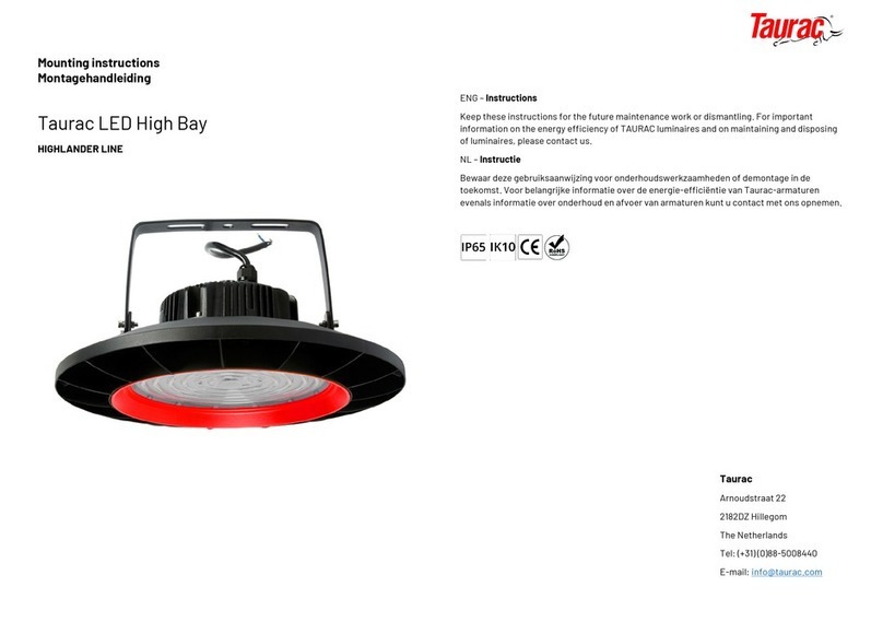
Taurac GALLOWAY User manual

1 2
Mounting instructions
Montagehandleiding
LED lighting
LED Downlight Galloway Arrow
GALLOWAY LINE
ENG – Instructions
Keep these instructions for the future maintenance work or dismantling. For
important information on the energy eciency of TAURAC luminaires and on
maintaining and disposing of luminaires, please contact us.
NL – Instructie
Bewaar deze gebruiksaanwzing voor onderhoudswerkzaamheden of
demontage in de toekomst. Voor belangrke informatie over de energie-
eciëntie van Taurac-armaturen evenals informatie over onderhoud en afvoer
van armaturen kunt u contact met ons opnemen.
Taurac
Arnoudstraat 22
2182DZ Hillegom
The Netherlands
Tel: (+31) (0)88-5008440
E-mail: info@taurac.com

3 4
ENG – Safety notes
These instructions assume expert knowledge corresponding to a completed professional education as an electrician.
Never work when voltage is present on the luminaire. In all cases, mains voltage must always be switched off before the
luminaire is connected to the installation.
The LED light source in the luminaire cannot and may not be changed or replaced by the user. In case of malfunctions
with the LED module, please contact Taurac.
If light management components are used in the luminaire, they comply with the SELV requirements. Use mains cables
for control inputs of dimmable ECG (1.. 10V, DALI, etc.) which are rated for 230V.
The maximum admissible ambient temperature (Ta) of the luminaire may not be exceeded. Surpassing that temperature
reduces the service life and, in extreme cases, poses risk of early failure. The luminaire is intended for use in an (indoor)
room with an ambient temperature of Ta = 25 ° C.
The equipment must only be used in conjunction with the product supplied driver. Or with a Taurac recommended
driver. Application not recommended drivers by Taurac can damage the xture and hence to limit the guarantee.
NL – Veiligheidsinstructies
Elektrotechnische werkzaamheden aan het armatuur mogen alleen worden uitgevoerd door een erkend installateur of
daartoe bevoegd en opgeleid, deskundig personeel.
Werkzaamheden aan het armatuur alleen uitvoeren in het geval deze geheel spanningsloos is. Netspanning dient in alle
gevallen altd eerst te worden uitgeschakeld voordat het armatuur op de installatie wordt aangesloten.
De led lichtbron in het armatuur kan en mag niet door de gebruiker gewzigd of vervangen worden. B het uitvallen van
of storingen aan de led(modules), verzoeken w u contact op te nemen met Taurac.
In het geval er lichtmanagement componenten i.c.m. het armatuur worden toegepast, dienen deze te voldoen aan de
SELV-eisen. De stuur- of dimbekabeling (o.a. DALI) en aansluitingen dienen netspanningsvast (230V) te zn uitgevoerd.
Overschrding van de voor dit product in de specicaties opgegeven maximale, toelaatbare omgevingstemperatuur (Ta)
kan tot gevolg hebben dat de levensduur van de leds in het armatuur wordt bekort of in uitzonderlke gevallen kan leiden
tot vervroegde uitval. De Ta mag dus niet worden overschreden, het armatuur is bedoeld voor toepassing in een (binnen)
ruimte met een omgevingstemperatuur van Ta = 25°C. Het armatuur mag alleen worden toegepast in combinatie met
een door Taurac geadviseerde e.o. met het product meegeleverde driver. Toepassing van niet door Taurac geadviseerde
drivers kan schade aan het armatuur aanbrengen en daarmee een beperking van de garantie tot gevolg hebben.
ENG – Installation Precautions
8. Do not drop light xture or expose it to impact with hard objects during transportation or installation to avoid
deformation, damage or danger.
9. Make sure the light xture and all the parts have been installed rmly to prevent from falling off.
10. The light xture and its parts should be examined regularly if any cracking occurs to ensure its function and safety.
11. Looking directly at bright light source for a long time will damage your eyesight.
12. For any abnormal lighting or problem that cannot be handled by yourself, please switch off the power supply
immediately and contact our customer service.
13. The outside springs of our light xtures are for 6mm~25mm thick ceiling board. For ceiling board thickness
outside this range, please consult with us for other products.
14. Please cut ceiling hole according to our recommended cut out hole size. Over 2mm deviation will cause diculty
in installation or mounting.
15. Connect light source and driver by quick-connect male/female terminal connectors wich are designed to
withstand 6kgs of pull-force. For separate the connectors, press the latch gently. An excessive force may result in
damage to wire or malfunction due to poor connection.
NL – Voorzorgsmaatregelen b de installatie
1. Zorg ervoor dat de netvoering is uitgeschakeld vóór de installatie.
2. De nominale spanning van het armatuur moet overeenkomen met de aanwezige netspanning.
3. Vervanging van of wziging aan onderdelen van het armatuur is niet toegestaan zonder voorafgaande toestemming
van de leverancier.
4. Indien een abnormale situatie wordt geconstateerd zoals losse onderdelen of lichtbron, afwkende geluiden, rook
of ikkering tdens het gebruik, wordt dringend verzocht de netspanning uit te schakelen voor inspectie.
5. Houdt het armatuur na inschakeling verwderd van ontvlambare materialen om het risico op brand of elektrische
schokken te vermden.
6. Het is niet toegestaan het armatuur anders dan voor verlichtingsdoeleinden toe te passen, zoals verwarming en
droging, om de veiligheid te kunnen blven garanderen.
7. Verzeker u ervan dat de netspanning is uitgeschakeld voorafgaand aan vervanging of reparatie. Zorg ervoor dat
het armatuur plus de aanliggende delen voldoende zn afgekoeld voordat met de werkzaamheden wordt gestart om
brandwonden en of elektrische schokken te voorkomen.
8. Voorkom schade aan het armatuur of de directe omgeving als gevolg van vallen, sterke schokken en trillingen
tdens transport of installatie.
9. Zorg ervoor dat het armatuur op de juiste wze wordt geïnstalleerd om te voorkomen dat deze los komt uit de
bevestiging.
10. Het armatuur en aangesloten onderdelen dienen regelmatig te worden gecontroleerd op beschadigingen om het
functioneren en de veiligheid te kunnen blven garanderen.
11. Direct oogcontact met de lichtbron in het armatuur moet worden vermeden om mogelke beschadiging van het
gezichtsvermogen te voorkomen.
12. In geval van afwkingen in de verlichting of problemen die u niet door uzelf kunnen worden opgelost, wordt
geadviseerd de netspanning onmiddellk uit te schakelen en contact op te nemen met de klantenservice van de
leverancier.
13. De montageveren van de armaturen zn geschikt voor een plafonddikte van 6-25mm max. B hiervan afwkende
plafondmaten verzoeken w u contact op te nemen met uw leverancier.
14. De overeenkomstige zaagopening voor het armatuur dient conform de opgegeven specicaties te worden
uitgevoerd. Afwkingen van meer dan 2mm kan problemen geven b de installatie of montage.
15. Aansluiting van het armatuur en de driver dient uitsluitend te worden uitgevoerd met de door de leverancier
geadviseerde dan wel meegeleverde, goedgekeurde male / female connectoren.
ENG – Installation Precautions
1. Please make sure the power is off before the installation.
2. The voltage rating of the light xture needs to match the voltage of power supply.
3. Any replacement or modication of internal parts without authorization is not allowed.
4. If any irregular condition such as loose parts or light source, abnormal sound, smoke, unusual
ash is found during operation, please disconnect the power immediately for inspection.
5. When the light xture works, keep it away from ammable materials to minimize the risk of re or electric shock.
6. It is forbidden to use the light xture other than lighting, such as heating or drying, to keep it safe.
7. Always be certain the power is off before the replacement or repair. Allow the light xture and surrounding parts to
cool suciently before handling to prevent a burn injury or electric shock.

5 6
ENG – Installation
NL – Installatie
ENG - Make sure the quick-connect terminals are fully engaged.
NL- Zorg ervoor dat de connectoren volledig met elkaar zn
verbonden.
ENG - Be certain the body structure has been
tightened.
NL - Wees er zeker van dat de ledmodule goed is
geborgd.
ENG - Cut ceiling hole according to our recommended cut out hole size and insert
the LED lamp set into the ceiling.
NL - Maak een gat in het plafond met de overeenkomstige inbouwmaat en installeer
de downlight in het plafond.
ENG - Do not use acid/alkaline cleaning agents or any volatile solvents such as
alcohol or paints to avoid material decay which may affect the lighting eciency.
NL - Gebruik geen zuur / alkaline reinigingsmiddelen, alcohol of vluchtige
oplosmiddelen e.d. om schade aan het materiaal te voorkomen, die de lichtkwaliteit
kunnen beïnvloeden.
ENG - Finish lamp. Ceiling board thickness: 6mm-25mm.
NL- Rond de installatie af. Plafondplaat dikte: 6 mm-25 mm.
Spring clips / Veerklemmen
ENG - For 4mm ceiling board or of special materials, please use spring clips.
NL - Gebruik voor een plafondplaat van 4mm of speciale materialen de veerklemmen.
ENG – Wiring Installation standard (switchable) driver
NL – Elektrische aansluiting standaard (schakelbare) driver
ENG - The wiring can be in stranded wires with fer-
rules or solid with a cross section of 0.5-1.5mm².
Strip 8.5–9.5 mm of insulation from the cables
to ensure perfect operation of the push-wire
terminals.
NL – De bedrading kan worden uitgevoerd met
soepele aders met adereindhulzen of met vaste
kern met een doorsnede van 0.5-1.5mm². De
draadisolatie aanstrippen over een lengte van
8,5 – 9 mm voor een optimale verbinding met het
push-in contact.
ENG - Use one wire for each terminal connector only.
NL – Plaats niet meer dan een ader per terminal contact

7 8
ENG - Loose wiring
NL - Losmaken draad
ENG - Push down the “push button and remove the cable from the front.
NL – Druk het verend contact in en verwder de draad
Note :
ENG - Check if the I-SELECT 2 resistor is correctly mounted in place
NL – Controleer of de I-SELECT 2 plug correct is aangesloten
ENG – Driver wiring connection:
NL – Bedradingschema driver:
ENG – DALI dim driver installation
NL – Installatie DALI-driver
1)
ENG – Switch of push-dim option
NL - Switch of push-dim functie
ENG - Phase (L), neutral (N), earth (PE), control line (DA/L’)
NL – Fase (L), nul (N), aarde (PE), schakelln (DA/L)
Remark / opmerking :
ENG – No need for controlline, thanks to bridging terminal N (4) and DA/N (8)
NL – Geen DALI sturing nodig, i.g.v. brug tussen aansluiting N (4) en DA/N (8)
ENG – Driver wiring connection:
NL – Bedradingschema driver:
ENG – DALI dim driver installation
NL – Installatie DALI-driver
2)
ENG – DALI-control option
NL - DALI besturing

910
ENG - Phase (L), neutral (N), earth (PE), control line (DA/L and DA/N)
NL – Fase (L), nul (N), aarde (PE), schakelln (DA/L en DA/N)
Remark / opmerking :
ENG – Control by a digital control signal (DSI or DALI)
NL – Regeling dmv digitale besturing (DSI of DALI)
ENG – Driver wiring connection:
NL – Bedradingschema driver:
ENG – Emergency driver installation
NL – Installatie noodverlichting driver
ENG _ When using the EM powerLED without a sensor, connect the terminals C/F and L link with a wire (bridge)
NL – Indien er geen sensor wordt toegepast, plaats dan een draadbrug tussen de contacten C/F en L link
ENG - The connected LED module will be used for mains and emergency operation.
NL – De aangesloten ledmodule zal zowel in continu als in noodbedrf functioneren
ENG - Mains (N, L, C/F, L link, S/L) LED (Led +, LED - ) Batteries (Bat +, Bat - ) Iset
NL - Netvoeding (N, L, C/F, L link, S/L) LED (Led +, LED - ) Accu (Bat +, Bat - ) Iset
ENG – Wiring
NL – Bedrading
ENG - Test switch and Indication
NL - Test knop en LED indicator
ENG - Release of the wiring
NL - Draad ontkoppelen

11 12
ENG - Use one wire for each terminal connector only
Use each strain relief channel for one cable (pre-x on bottom green cover)
NL- Per connector uitsluitend een draad plaatsen
Eén kabel per trekontlasting toepassen (zie onderzde groene afdekkap)
ENG - Mounting hole 6.5 mm diameter. Connect wires to terminals Orange (+) and Pink (-) on the emergency driver.
NL – Gatmaat diameter 6.5mm. Sluit bedrading aan op de aansluitingen Orange (+) en Pink (-) op de noodverlichtings
driver.
ENG – Fixing conditions emergency driver
NL – Positionering noodverlichtingsdriver
NL – Vocht-, zuur-, olie en vetvr. De maximum omgevingstemperatuur (ta), zoals in de
productspecicaties en op de component aangegeven en afhankelk van het aangesloten armatuur, mag niet worden
overschreden. Niet geschikt voor montage in een hoek.
ENG – Led status indicator
NL – Led status indicator
©2020 TAURAC
Technical data, dimensions and weight are subject to change. Errors and changes reserved.
Technische gegevens, afmetingen en gewicht onder voorbehoud. Fouten en wzigingen voorbehouden.
ENG - Dry, acidfree, oilfree, fatfree. It is not allowed to exceed the maximum ambient temperature (ta) stated on the
device. Minimum distances stated below are recommendations and depend on the actual luminaire. Is not suitable for
xing in corner.
Other Taurac Lighting Equipment manuals
Popular Lighting Equipment manuals by other brands

Show Tec
Show Tec 42512 manual
Solar Goes Green
Solar Goes Green SGG-PIR-54 owner's manual
Show Tec
Show Tec SpaceTracer 2000 CMY manual
Show Tec
Show Tec Colour Star Sky II DMX V4 Product guide
Claypaky
Claypaky SINFONYA PROFILE 600 instruction manual

Heath Zenith
Heath Zenith LED Lighted Push Button with Keyfinder Light... owner's manual
Pure line
Pure line Above Ground Pool Gate installation manual
Qlight
Qlight STNDL-N quick start guide

COLORKINETICS
COLORKINETICS ColorBlast 12 Powercore user guide

HAMPTON BAY
HAMPTON BAY 1000000000 Use and care guide
C.P. Electronics
C.P. Electronics EBR-4SC Product guide

Show Tec
Show Tec LED Par 56 Ultra Bright RGB instructions
