manuals.online logo
Brands
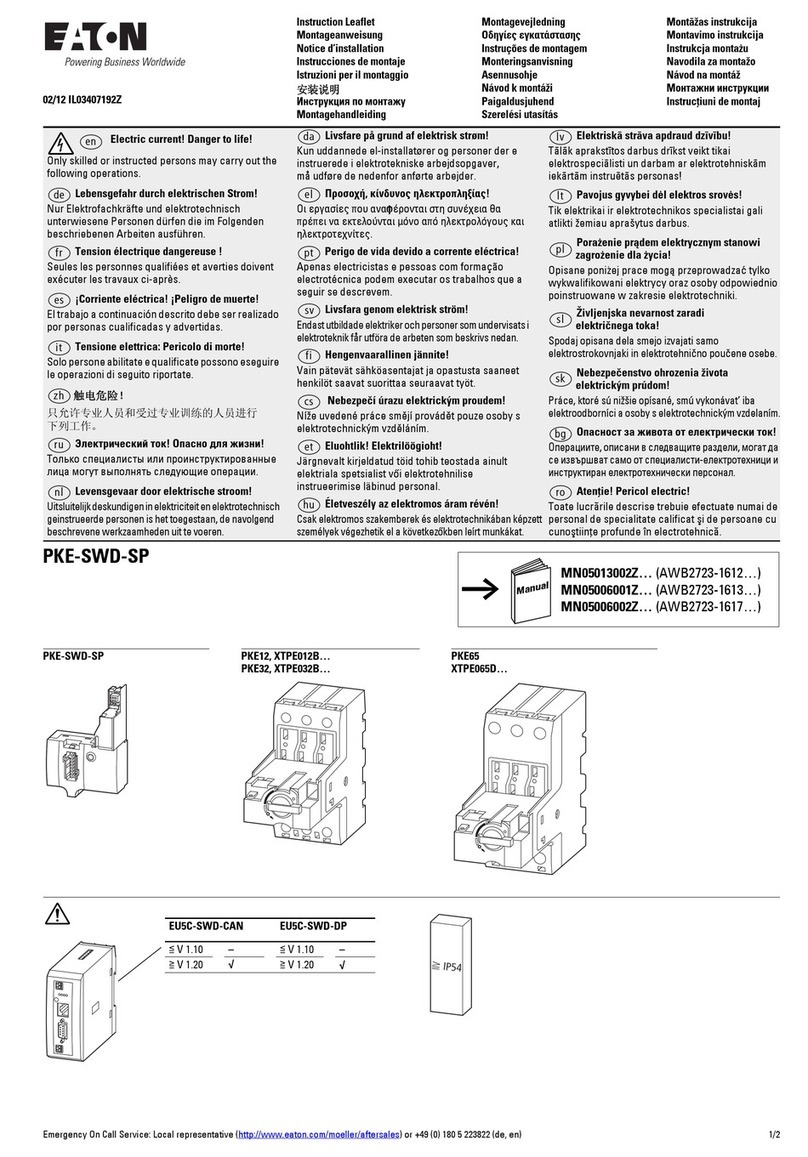
  1. Home
  2. •
  3. Brands
  4. •
  5. Eaton
  6. •
  7. Circuit Breaker
  8. •
  9. Eaton 150VCP-W Series User manual

Eaton 150VCP-W Series User manual

15kV VCP-W
Interactive Instructions
Visual Instruction Booklet Essentials | 150VCP-W 25kA 1200A |January 2017
Supplemental Material For 15kV VCP-W
This is a user interactive supplemental booklet. This material is
intended to enhance the technical information included in
the instruction booklet for the 15kV VCP-W circuit breaker
manufactured by Eaton.
Supplemental Material
For 15kV Element
WARNING
INSTALLATION OR MAINTENANCE SHOULD BE ATTEMPTED
ONLY BY QUALIFIED PERSONNEL. THIS SUPPLEMENTAL
INSTRUCTION BOOKLET IS INTENDED TO ACCOMPANY
THE ORIGINAL INSTRUCTION BOOKLET PROVIDED WITH
THE VCP-W CIRCUIT BREAKER AND SHOULD NOT BE
CONSIDERED ALL INCLUSIVE REGARDING INSTALLATION
OR MAINTENANCE PROCEDURES. THIS IS NOT TO BE USED
IN PLACE OF THE VCP-W CIRCUIT BREAKER INSTRUCTION
BOOKLET. IF FURTHER INFORMATION IS REQUIRED, YOU
SHOULD CONSULT EATON.
IMPROPERLY INSTALLING OR MAINTAINING THESE
PRODUCTS CAN RESULT IN DEATH, SERIOUS PERSONAL
INJURY OR PROPERTY DAMAGE.
READ AND UNDERSTAND THE VCP-W INSTRUCTION
BOOKLET BEFORE ATTEMPTING ANY OPERATION OR
MAINTENANCE OF THE CIRCUIT BREAKERS.
THE CIRCUIT BREAKERS FEATURED IN THIS BOOKLET
ARE DESIGNED AND TESTED TO OPERATE WITHIN THEIR
NAMEPLATE RATINGS. OPERATION OUTSIDE OF THESE
RATINGS MAY CAUSE THE EQUIPMENT TO FAIL, RESULTING
IN DEATH, BODILY INJURY AND PROPERTY DAMAGE.
ALL SAFETY CODES, SAFETY STANDARDS AND/OR
REGULATIONS AS THEY MAY BE APPLIED TO THIS TYPE OF
EQUIPMENT MUST BE STRICTLY ADHERED TO.
THESE VACUUM REPLACEMENT CIRCUIT BREAKERS ARE
DESIGNED TO BE INSTALLED PURSUANT TO THE AMERICAN
NATIONAL STANDARDS INSTITUTE (ANSI). SERIOUS
INJURY, INCLUDING DEATH, CAN RESULT FROM FAILURE TO
FOLLOW THE PROCEDURES OUTLINED IN THIS BOOKLET.
ALL POSSIBLE CONTINGENCIES WHICH MIGHT ARISE
DURING INSTALLATION, OPERATION, OR MAINTENANCE,
AND ALL DETAILS AND VARIATIONS OF THIS EQUIPMENT
ARE NOT COVERED BY THESE INSTRUCTIONS. IF FURTHER
INFORMATION IS DESIRED BY THE PURCHASER REGARDING
A PARTICULAR INSTALLATION, OPERATION, OR
MAINTENANCE OF THIS EQUIPMENT, THE LOCAL EATON’S
ELECTRICAL SERVICES & SYSTEMS REPRESENTATIVE
SHOULD BE CONTACTED.
WARNING
TO PROTECT THE PERSONNEL ASSOCIATED WITH
INSTALLATION, OPERATION, AND MAINTENANCE OF THESE
CIRCUIT BREAKERS, THE FOLLOWING PRACTICES MUST BE
FOLLOWED:
•Read the instruction booklet provided with the
VCP-W circuit breaker before attempting any
installation, operation or maintenance of these
circuit breakers.
•Only qualified persons, as defined in the National
Electrical Safety Code, who are familiar with the
installation and maintenance of medium voltage
circuits and equipment, should be permitted to
work on these circuit breakers.
•Always remove the circuit breaker from the
enclosure before performing any maintenance.
Failure to do so could result in electrical shock
leading to death, severe personnel injury or
property damage.
•Do not work on a circuit breaker with the
secondary test coupler engaged. Failure to
disconnect the test coupler could result in an
electrical shock leading to death, personnel
injury or property damage.
•Do not work on a closed circuit breaker or a
circuit breaker with closing springs charged.
The closing spring should be discharged and the
main contacts open before working on the circuit
breaker. Failure to do so could result in cutting or
crushing injuries.
•Do not use a circuit breaker by itself as the
sole means of isolating a high voltage circuit.
Remove the circuit breaker to the Disconnect
position and follow all lockout and tagging rules
of the National Electrical Code and any and all
applicable codes, regulations and work rules.
•Do not leave the circuit breaker in an
intermediate position in the cell. Always have the
circuit breaker either in the Test or Connected
position. Failure to do so could result in a flash
over and possible death, personnel injury or
property damage.
•Always remove the maintenance tool from the
circuit breaker after charging the closing springs.
•Circuit breakers are equipped with safety
interlocks. Do not defeat them. This may result in
death, bodily injury or equipment damage.
Table of Contents
Vacuum Interrupter
Vacuum Interrupter 3
Vacuum Interrupter Assembly 3
Vacuum Interrupter Integrity Test
Vacuum Interrupter Integrity Testing Configuration 4
Insulation Integrity Test
Power Frequency Withstand Voltage Testing Configuration 5
Current Path Resistance Test
Current Path Resistance Testing Procedure 6
Vacuum Bottle Contact Inspection
Contact Erosion Indicator 7
Contact Wipe and Stroke 7
Mechanism Lubrication
150VCP-W Mechanism Lubrication 8
Component Replacement
Replacing The Charging Motor 9
Replacing Spring Release and Shunt Trip Coils 10
Component Installation 11
Installation of Second Shunt Trip 11
Undervoltage Trip Device 12
Component Adjustment 13
Adjustment of the Motor Cutoff Switch 13
Adjustment of the Operations Counter 14
CloSure™ Test 15
CloSure™ Test 13
VCP-W Circuit Breaker Model 16
VCP-W 5/15 63kA 3000A 16
2
EATON |Visual Instruction Booklet Essentials | 150VCP-W 25kA 1200A | January 2017
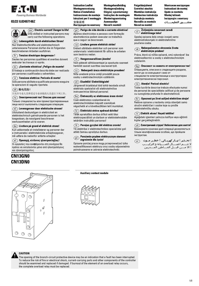
Vacuum Interrupter
Vacuum interrupters offer the advantages of enclosed
arc interruption, small size and weight, longer life,
reduced maintenance, minimal mechanical shock,
and elimination of contact degradation caused by
environmental contamination.
In the closed position, current flows through the
interrupter moving and fixed stems and the faces
of the main contacts. As the contacts part, an arc is
drawn between the contact surfaces. The arc is rapidly
moved away from the main contacts to the slotted
contact surfaces by self-induced magnetic effects. This
minimizes contact erosion and hot spots on the contact
surfaces. The arc flows in an ionized metal vapor and as
the vapor leaves the contact area, it condenses into the
metal shield which surrounds the contacts.
At current zero, the arc extinguishes and vapor
production ceases. Very rapid dispersion, cooling,
recombination, and de-ionization of the metal vapor
plasma and fast condensation of metal vapor causes the
vacuum to be quickly restored and prevents the transient
recovery voltage from causing a restrike across the gap
of the open contacts.
Vacuum Interrupter Assembly
Each interrupter is assembled at the factory as a unit
to assure correct dimensional relationships between
working components. The interrupter assembly consists
of a vacuum interrupter, a molded glass polyester stand-
off insulator, upper and lower clamps, flexible shunts,
bell crank, operating rod, and contact load spring. The
vacuum interrupter is mounted vertically with a fixed
stationary stem and a moving stem to open and close
the contacts. The upper and lower glass polyester
stand-off insulator and clamps support the interrupter
and are fastened to the circuit breaker’s stored energy
mechanism frame. Upper and lower flexible shunts
provide electrical connections from each interrupter to
the circuit breaker’s primary bushings while providing
isolation from mechanical shock and movement of the
interrupter’s moving stem. The operating rod, loading
spring, and bell crank transfer mechanical motion from
the circuit breaker’s operating mechanism to the moving
stem of the interrupter. A vacuum interrupter contact
erosion indicator is located on the moving stem of
the interrupter. It is visible when the circuit breaker is
withdrawn and is viewed from the rear of the circuit
breaker.
Vacuum
Interrupter
3
EATON |Visual Instruction Booklet Essentials | 150VCP-W 25kA 1200A | January 2017
WARNING
APPLYING ABNORMALLY HIGH VOLTAGE ACROSS A PAIR
OF CONTACTS IN VACUUM MAY PRODUCE X-RADIATION.
THE RADIATION MAY INCREASE WITH THE INCREASE
IN VOLTAGE AND/OR DECREASE IN CONTACT SPACING.
X-RADIATION PRODUCED DURING THIS TEST WITH
RECOMMENDED VOLTAGE AND NORMAL CONTACT
SPACING IS EXTREMELY LOW AND WELL BELOW
MAXIMUM PERMITTED BY STANDARDS. HOWEVER, AS
A PRECAUTIONARY MEASURE AGAINST POSSIBILITY OF
APPLICATION OF HIGHER THAN RECOMMENDED VOLTAGE
AND/OR BELOW NORMAL CONTACT SPACING, IT IS
RECOMMENDED THAT ALL OPERATING PERSONNEL STAND
AT LEAST ONE METER AWAY IN FRONT OF THE CIRCUIT
BREAKER.
Vacuum Interrupter Integrity Test
ote:NRoll over each high potential test diagram configuration above to see the
correct lead connection to the equipment.
ote:NThe secondary disconnect must be grounded during test.
Vacuum interrupters used in Type VCP-W circuit
breakers are highly reliable interrupting elements.
Satisfactory performance of these devices is dependent
upon the integrity of the vacuum in the interrupter and
the internal dielectric strength. Both of these parameters
can be readily checked by a one minute ac high potential
test, using the appropriate test voltage in the following
table.
Circuit breaker Rated Maximum
Voltage
Vacuum Interrupter Integrity
Test Voltage
ac 60Hz
5 kV 20 kV
7.5 kV / 15 kV 27 kV
WARNING
DC HI-POTENTIAL TESTS ARE NOT RECOMMENDED BY EATON. DO NOT APPLY
DC AT ANY LEVEL TO VCP-W POWER CIRCUIT BREAKERS.
With the circuit breaker open and securely sitting on the floor, connect
all top/front primary studs (bars) together and the high potential machine
lead. Connect all bottom/rear studs together. Do not ground them to
the circuit breaker frame. Start the machine at zero potential, increase to
appropriate test voltage and maintain for one minute.
Successful withstand indicates that all interrupters have satisfactory
vacuum level. If there is a breakdown, the defective interrupter or
interrupters should be identified by an individual test and replaced before
placing the circuit breaker in service.
After the high potential unit is removed, discharge any electrical charge
that may be retained. This charge is particularly true from the center shield
of vacuum interrupters. To avoid any ambiguity in the ac high potential
test due to leakage or displacement (capacitive) current, the test unit
should have sufficient volt-ampere capacity. It is recommended that the
equipment be capable of delivering 25 milliamperes for one minute.
The current delivery capability of 25 mA ac applies when all three VI’s are
tested in parallel. If individual VI’s are tested, current capability may be one
third of this value.
Vacuum Interrupter Integrity Testing Configuration
OS Lead = Output Signal Lead
G/R Lead = Ground / Return Lead
OS
Lead CBA
G/R
Lead
OS
Lead CBA
G/R
Lead
OS
Lead CBA
G/R
Lead
OS
Lead CBA
G/R
Lead
OS
Lead CBA
G/R
Lead
OS
Lead CBA
G/R
Lead
OS
Lead CBA
G/R
Lead
OS
Lead
CBA
G/R
Lead
OS
Lead
CBA
G/R
Lead
OS
Lead
CBA
G/R
Lead
4
EATON |Visual Instruction Booklet Essentials | 150VCP-W 25kA 1200A | January 2017
Primary Circuit:
The integrity of primary insulation may be checked by the ac high potential
test. The test voltage depends upon the maximum rated voltage of the
circuit breaker. For the circuit breakers rated 4.76 kV, 8.25 kV and 15 kV
the test voltages are 15 kV, 27 kV and 27 kV RMS, 60 Hz respectively.
Conduct the test as follows:
Close the circuit breaker. Connect the high potential lead of the test
machine to one of the poles of the circuit breaker. Connect the remaining
poles and circuit breaker frame to ground. Start the machine with output
potential at zero and increase to the test voltage. Maintain the test voltage
for one minute. Repeat for the remaining poles. Successful withstand
indicates satisfactory insulation strength of the primary circuit.
Open the circuit breaker. Connect the high potential lead of the test
machine to one of the poles of the circuit breaker. Connect the remaining
poles and circuit breaker frame to ground. Start the machine with output
potential at zero and increase to the test voltage. Maintain the test voltage
for one minute. Repeat for the remaining poles. Successful withstand
indicates satisfactory insulation strength of the primary circuit.
WARNING
APPLYING ABNORMALLY HIGH VOLTAGE ACROSS A PAIR
OF CONTACTS IN VACUUM MAY PRODUCE X-RADIATION.
THE RADIATION MAY INCREASE WITH THE INCREASE
IN VOLTAGE AND/OR DECREASE IN CONTACT SPACING.
X-RADIATION PRODUCED DURING THIS TEST WITH
RECOMMENDED VOLTAGE AND NORMAL CONTACT
SPACING IS EXTREMELY LOW AND WELL BELOW
MAXIMUM PERMITTED BY STANDARDS. HOWEVER, AS
A PRECAUTIONARY MEASURE AGAINST POSSIBILITY OF
APPLICATION OF HIGHER THAN RECOMMENDED VOLTAGE
AND/OR BELOW NORMAL CONTACT SPACING, IT IS
RECOMMENDED THAT ALL OPERATING PERSONNEL STAND
AT LEAST ONE METER AWAY IN FRONT OF THE CIRCUIT
BREAKER.
Insulation Integrity Test
ote:NRoll over each high potential test diagram configuration above to see the
correct lead connection to the equipment.
ote:NThe ground connection can be attached to the plated frame.
ote:NThe secondary disconnect must be grounded during test.
In VCP-W circuit breakers, insulation maintenance
primarily consists of keeping all insulating surfaces
clean. This can be done by wiping off all insulating
surfaces with a dry lint free cloth or dry paper towel.
In case there is any tightly adhering dirt that will not
come off by wiping, it can be removed with a mild
solvent or distilled water. But be sure that the surfaces
are dry before placing the circuit breaker in service. If
a solvent is required to cut dirt, use Isopropyl Alcohol
or commercial equivalent. Secondary control wiring
requires inspection for tightness of all connections and
damage to insulation.
Power Frequency Withstand Voltage Testing Configuration: Open Circuit
Power Frequency Withstand Voltage Testing Configuration: Closed Circuit
OS Lead = Output Signal Lead
G/R Lead = Ground / Return Lead
OS
Lead CBA
G/R
Lead
OS
Lead CBA
G/R
Lead
OS
Lead CBA
G/R
Lead
OS
Lead CBA
G/R
Lead
OS
Lead CBA
G/R
Lead
OS
Lead CBA
G/R
Lead
OS
Lead CBA
G/R
Lead
OS
Lead
CBA
G/R
Lead
OS
Lead
CBA
G/R
Lead
OS
Lead
CBA
G/R
Lead
5
EATON |Visual Instruction Booklet Essentials | 150VCP-W 25kA 1200A | January 2017
Current Path Resistance Test
Purpose
To measure and record the dc electrical resistance
of the main current carrying pole unit assembly in
the VCP-W power circuit breaker. This measurement
is performed by injecting 100A dc from terminal to
terminal of each pole unit in the closed position and
measuring the voltage drop across the terminals. The
resistance can be calculated from Ohm’s Law and is
expressed in micro-ohms.
The main contacts are inside the vacuum chamber,
which remain clean and require no maintenance at
any time. The design does not have sliding contacts at
the moving stem and use a highly reliable and unique
flexible clamp design that eliminates the need for
lubrication and inspection for wear.
This test may be performed during regular maintenance
intervals and the results should not exceed the factory
recorded values by 15% when adjusted to the same
temperature recorded during the factory tests.
Equipment
This test should be performed with a low voltage,
direct current (dc) power supply capable of delivering
no less 100A dc. The factory performs this test using a
Digital Low Resistance Ohmmeter (DLRO). The DLRO
injects 100A dc, measures the voltage drop across the
terminals and displays the resistance in micro-ohms.
Procedure
The current path resistance test is to be performed per
ANSI/IEEE C37.09-1999 section 5.15.
Test
Perform the test as follows (Using the DLRO)
1. Remove the circuit breaker from its enclosure
if installed (follow the removal procedures) and
move it to a suitable area away from the Arc-Flash
boundary.
2. Remove the finger clusters from the terminals being
tested.
3. Manually or electrically charge the circuit breaker.
4. Manually or electrically close the circuit breaker. If
the circuit breaker is being closed electrically, the
charging motor will run if control power is present
after the circuit breaker is closed.
5. Provide control power to the DLRO and turn it to the
ON position. Select 100A output, if adjustable.
6. Connect the DLRO positive current lead to the TOP
terminal of the phase being tested.
7. Connect the DLRO negative current lead to the
BOTTOM terminal of the phase being tested.
8. Press the TEST button on the DLRO. Once the
TEST button is pressed, 100A dc will flow through
the phase being tested. If the circuit breaker is not
closed, the DLRO will not inject current.
9. Apply the DLRO positive measurement test lead
to the TOP terminal. Be mindful not to connect this
measurement lead to the current lead. This insures
that the current lead is not being calculated into the
resistance of the current path.
10. Apply the DLRO negative measurement test lead to
the BOTTOM terminal. Be mindful not to connect
this measurement lead to the current lead. This
insures that the current lead is not being calculated
into the resistance of the current path.
11. While both measurement leads are connected,
observe the resistance reading and record the value.
12. Press the TEST button on the DLRO to stop the
current flow.
13. Remove the measurement leads and current leads
from the phase being tested.
14. Install the finger clusters back onto the terminals of
the circuit breaker.
15. Repeat above procedure for the remain phases of
the circuit breaker.
16. Open the circuit breaker after completion of the
testing.
17. Turn the DLRO to the OFF position and remove
control power if necessary.
18. Re-insert the circuit breaker into the enclosure per
insertion procedures.
Results
The field measured resistance should not exceed the
factory values by more than 15%. If measurements
exceed 15%, check the primary current path for loose
hardware and re-torque per the VCP-W instruction
booklet. Repeat the test if any loose hardware was
found and re-torqueing was applied. If the values do not
improve, contact the manufacturer.
Resistance conversion for Temperature
Rconversion = RFactory ( 1 + ( TField - TFactory ) r)
Rconversion = Resistance correction for temperature based from the factory
resistance measurement.
RFactory = Resistance measurement from the factory.
TField = Temperature measurement in the field.
TFactory = Temperature measurement from the factory.
r= Copper resistivity temperature coefficient.
r= 0.002167 Copper Resistivity Temperature Coefficient / Deg F
r= 0.0039 Copper Resistivity Temperature Coefficient / Deg C
Resistance Converter (In Degrees Fahrenheit):
Rconversion Field =o F
RFactory : TFactory: TField :
6
EATON |Visual Instruction Booklet Essentials | 150VCP-W 25kA 1200A | January 2017
0.000
WARNING
THERE IS NO PROVISION FOR IN-SERVICE ADJUSTMENTS
OF CONTACT WIPE AND STROKE. ALL SUCH ADJUSTMENTS
ARE FACTORY SET AND SHOULD NOT BE ATTEMPTED IN
THE FIELD.
Contact Erosion Indicator
Eaton’s VCP-W vacuum contacts are contained
inside the interrupter, where they remain clean and
require no maintenance. However, during high current
interruptions there may be a minimal amount of erosion
from the contact surfaces. If contact erosion reaches
approximately 1/8 inch, the interrupter must be replaced.
The purpose of the contact erosion indicator is to
monitor the erosion of the vacuum interrupter contacts.
A contact erosion indicator mark is located on the
moving stem of the interrupter.
In order to determine if the contacts have eroded to the
extent that the interrupter must be replaced, close the
circuit breaker and observe the erosion mark placed on
each vacuum interrupter moving stem from the rear of
the circuit breaker. If the mark on the interrupter stem
is visible, erosion has not reached maximum value thus
indicating satisfactory contact surface of the interrupter.
If the mark is no longer visible, the vacuum interrupter
assembly must be replaced.
The erosion indicator is easily viewed from the rear of
the circuit breaker element.
Vacuum Bottle Contact Inspection
WARNING
FAILURE TO REPLACE A VACUUM INTERRUPTER ASSEMBLY
WHEN CONTACT EROSION MARK IS NOT VISIBLE OR WIPE
IS UNSATISFACTORY, WILL CAUSE THE CIRCUIT BREAKER
TO FAIL TO INTERRUPT AND THEREBY CAUSE PROPERTY
DAMAGE OR PERSONNEL INJURY.
Contact Wipe and Stroke
Contact wipe is the indication of (1) the force holding the
vacuum interrupter contacts closed and (2) the energy
available to hammer the contacts open with sufficient
speed for interruption.
Stroke is the gap between fixed and moving contacts of
a vacuum interrupter with the circuit breaker open.
The circuit breaker mechanism provides a fixed amount
of motion to the operating rods. The first portion of the
motion is used to close the contacts (i.e. stroke) and the
remainder is used to further compress the preloaded
wipe spring. This additional compression is called wipe.
Wipe and stroke are thus related to each other. As the
stroke increases due to the erosion of contacts, the
wipe decreases. A great deal of effort and ingenuity has
been spent in the design of the VCP-W circuit breakers,
in order to eliminate any need for field adjustment of
wipe or stroke.
The adequacy of contact wipe, as well as the overall
system condition, can be determined by simply
observing the vacuum interrupter side of the operating
rod assembly on a closed circuit breaker. The visible
“T” shape cutout on the loading spring is an indicator
used to determine whether the loading springs are
maintaining the proper contact pressure to keep the
contacts closed. Severe contact erosion would result
in an unacceptable implication from the “T” shape
indicator. If the wipe is not adequate, the vacuum
interrupter assembly (Pole Unit) must be replaced. Field
adjustment of the vacuum interrupter assembly is not
possible.
ote:NIt may be necessary to use a small mirror and flashlight
to clearly see the “T” shape indicator. The figure below shows
the procedure for determining the contact wipe of each spring
type.
If any part of the Red or Gray
indicator is visible:
“Wipe” is Satisfactory.
If any part of the Indicator is
visible:
“Wipe” is Satisfactory.
If any part of the T-Shape Cutout
indicator is visible:
“Wipe” is Satisfactory.
If any part of the Red or Gray
indicator is NOT visible:
“Wipe” is Unsatisfactory.
If any part of the Indicator is
NOT visible:
“Wipe” is Unsatisfactory.
If any part of the T-Shape Cutout
indicator is NOT visible:
“Wipe” is Unsatisfactory.
Contact Wipe and Stroke: White Contact Springs
Contact Wipe and Stroke: Orange Contact Springs
Contact Wipe and Stroke: Blue, Red, or Brown Contact Springs
ote:N Click the image below to view a satisfactory contact wipe and stroke.
7
EATON |Visual Instruction Booklet Essentials | 150VCP-W 25kA 1200A | January 2017
Mechanism
Lubrication
Proper Lubrication Times Per Rating
RATINGS OPERATIONS
29kA and below
Above 29kA
3000 Amp
750
400
400
150VCP-W Mechanism Lubrication
All parts that require lubrication have been lubricated
during the assembly with molybdenum disulphide
grease. Eaton No. 53702AM. Over a period of time,
this lubricant may be pushed out of the way or degrade.
Proper lubrication at regular intervals is essential for
maintaining the reliable performance of the mechanism.
The circuit breaker should be relubricated once a year or
per the operations table, which ever comes first with a
non-synthetic light machine oil.
After lubrication, operate the circuit breaker several
times manually and electrically.
Roller bearings are used on the pole shaft, the cam
shaft, the main link and the motor eccentric. These
bearings are packed at the factory with a top grade slow
oxidizing grease which normally should be effective for
many years. They should not be disturbed unless there
is definite evidence of sluggishness, dirt or parts are
dismantled for some reason.
If it becomes necessary to disassemble the mechanism,
the bearings and related parts should be thoroughly
cleaned, remove old grease in a good grease solvent.
Do not use carbon tetrachloride. They should then be
washed in light machine oil until the cleaner is removed.
After the oil has been drawn off, the bearings should be
packed with Eaton Grease 53702AM or equivalent.
8
EATON |Visual Instruction Booklet Essentials | 150VCP-W 25kA 1200A | January 2017
Replacement Parts
ITEMS DESCRIPTION EATON STYLE NUMBER
SPRING CHARGING MOTOR
(QUICK DISCONNECT)
48Vdc
125Vdc / 120Vac
250Vdc / 240Vac
699B196G03
699B196G01
699B196G02
SPRING CHARGING MOTOR
(RING TERMINALS)
48Vdc
125Vdc / 120Vac
250Vdc / 240Vac
699B196G06
699B196G04
699B196G05
Component
Replacement
WARNING
VERIFY CIRCUIT BREAKER IS OPEN, CLOSING SPRINGS ARE
DISCHARGED, AND CONTROL POWER IS DISCONNECTED.
Replacing The Charging Motor
Remove the motor leads from TB7 and TB8.
Remove the spring holding the ratchet pawl in the
center section of the mechanism; lift the pawl up out of
the way.
Rotate eccentric on the motor shaft to the top end of
the motor.
Unscrew the eccentric counterclockwise – use a
wooden hammer handle to break the threads
Remove the two screws on the right hand motor
support plate, using a 9/64in. Allen wrench. Remove
the motor plate from the side sheet for the 5kV circuit
breaker.
Remove the motor.
Verify the new motor has the correct motor voltage on
the motor sticker.
Lubricate the motor threads using molybdenum disulfide
grease, Eaton No. 53702AM or equal.
Position the new motor in place and install eccentric in a
clockwise direction.
Install the motor plate if it was previously removed.
Secure the motor in place using the two Allen head
screws.
Install the ratchet pawl spring.
Rewire the motor leads to the terminal block; Black on
TB8, and White on TB7.
Replacing the charging motor on a 150VCP-W25 mechanism.
9
EATON |Visual Instruction Booklet Essentials | 150VCP-W 25kA 1200A | January 2017
Replacement Parts
ITEMS DESCRIPTION EATON STYLE NUMBER
SPRING RELEASE COILS / SHUNT TRIPS
(QUICK DISCONNECT)
24Vdc
48Vdc
125Vdc / 120Vac
250Vdc / 240Vac
3759A76G04
3759A76G01
3759A76G02
3759A76G03
SPRING RELEASE COILS / SHUNT TRIPS
(RING TERMINALS)
24Vdc
48Vdc
125Vdc / 120Vac
250Vdc / 240Vac
3759A76G14
3759A76G11
3759A76G12
3759A76G13
WARNING
VERIFY CIRCUIT BREAKER IS OPEN, CLOSING SPRINGS ARE
DISCHARGED AND CONTROL POWER IS DISCONNECTED.
REFERENCE: THE SPRING RELEASE COIL IS THE COIL ON THE
LEFT SIDE, LOOKING INTO THE CIRCUIT BREAKER, WITH
THE GREEN “PUSH TO CLOSE” LABEL. THE SHUNT TRIP
COIL IS THE COIL ON THE RIGHT SIDE, LOOKING INTO THE
CIRCUIT BREAKER, WITH THE RED “PUSH TO OPEN” LABEL.
Replacing Spring Release and Shunt Trip Coils
Cut 4 to 6 tie wraps that hold the wires that go between
the close and trip coils to the terminal block in the lower
right side of the mechanism.
Remove two wires from the terminal block (TB1 and
TB2 for the Spring Release Coil/Close Coil and TB3 and
TB4 for the Shunt Trip Coil) and pull the wires through
the support bracket toward the coil.
Remove the 5/16 x 3 ¼ in. hex head bolt, lock washer
and spacer that hold the coil in place. Be careful to
capture the two fiber insulating washers behind the coil.
ote:NThe 5/16 x 3 ¼ in. bolt is made of silicon bronze for
magnetic purposes and must never be replaced with a steel
bolt.
Slide the coil out of its bracket (to its available open
side) and feed the wires through. Remove the metal
core from the center of the coil.
Install new wire markers on the new coil leads. Polarity
is not an issue.
Insert the metal core into the center of the new coil.
Fish the coil wires through the cut out and slide coil into
the bracket while gently pulling the leads.
Insert the bolt, lock washer and spacer and place the
two fiber washers on the bolt when it exits the coil
(one at a time and screw bolt into washers). Screw bolt
into threaded insert in bracket and tighten. Do not over
tighten!
Fish wires through to the terminal block. Connect wires
to terminal block (TB1 and TB2 for the Spring Release
Coil/Close Coil and TB3 and TB4 for the Shunt Trip Coil)
. Install tie wraps to hold wire bundle.
Mechanically and electrically test the circuit breaker and
hipot the secondary wiring.
Component
Replacement
Replacing the shunt trip coil on a 150VCP-W25 mechanism.
10
EATON |Visual Instruction Booklet Essentials | 150VCP-W 25kA 1200A | January 2017
Replacement Parts
ITEMS DESCRIPTION EATON STYLE NUMBER
SHUNT TRIP KIT (QUICK DISCONNECT) 24Vdc
48Vdc
125Vdc / 120Vac
250Vdc / 240Vac
694C636G04
694C636G01
694C636G02
694C636G03
SHUNT TRIP KIT (RING TERMINALS) 24Vdc
48Vdc
125Vdc / 120Vac
250Vdc / 240Vac
8794C81G14
8794C81G11
8794C81G12
8794C81G13
WARNING
VERIFY CIRCUIT BREAKER IS OPEN, CLOSING SPRINGS ARE
DISCHARGED AND CONTROL POWER IS DISCONNECTED.
REFERENCE: THE SPRING RELEASE COIL IS THE COIL ON THE
LEFT SIDE, LOOKING INTO THE CIRCUIT BREAKER, WITH
THE GREEN “PUSH TO CLOSE” LABEL. THE SHUNT TRIP
COIL IS THE COIL ON THE RIGHT SIDE, LOOKING INTO THE
CIRCUIT BREAKER, WITH THE RED “PUSH TO OPEN” LABEL.
Installation of Second Shunt Trip
Make sure all warnings are adhered to and circuit
breaker is closed and discharged.
Make sure area is prepared for installation of 2nd Shunt
Trip, move wires down out of the way.
ote:NRouting of wires, make sure 2nd Shunt trip wires route
the same way.
Place aluminum shim on back of 2nd shunt trip as
shown.
Hold shim in place while you begin installation.
Make sure wires are routed through the same opening
as the existing.
Install 2nd Shunt Trip next to existing Push to Open
Assembly as shown, hand tighten center bolt. Make
sure aluminum shim does not fall out. Make sure steel
brackets that stick out to the left are properly oriented as
shown.
Install .312-18 X .625 socket head capscrew in lower
right hole in 2nd Shunt Trip Bracket as shown. This uses
a .250-20 Hex Allen Wrench.
Tighten socket head capscrew as shown, making sure
aluminum shim is still in place. Tighten center .312-18
hex bolt using a ½” or 13mm socket or wrench.
Attach wires to the 5th and 6th location on the terminal
block as shown. Use wire ties as needed to bundle
wires together so they do not interfere with other
components.
Component
Installation
Installing a second shunt trip coil on a 150VCP-W25 mechanism.
11
EATON |Visual Instruction Booklet Essentials | 150VCP-W 25kA 1200A | January 2017
Replacement Parts
ITEMS DESCRIPTION EATON STYLE NUMBER
UNDERVOLTAGE FIELD INSTALLATION KIT
& INSTRUCTIONS (QUICK DISCONNECT)
48Vdc
125Vdc
250Vdc
120Vac
240Vac
691C274G01
691C274G02
691C274G03
691C274G04
691C274G05
UNDERVOLTAGE FIELD INSTALLATION KIT
& INSTRUCTIONS (RING TERMINALS)
48Vdc
125Vdc
250Vdc
120Vac
240Vac
8794C81G01
8794C81G02
8794C81G03
8794C81G04
8794C81G05
WARNING
BEFORE ATTEMPTING THIS INSTALLATION, VERIFY CIRCUIT
BREAKER IS OPEN, CLOSING SPRINGS ARE DISCHARGED
AND CONTROL POWER IS DISCONNECTED.
Undervoltage Trip Device
The undervoltage trip device for VCP-W circuit breakers
is an electromechanical device that operates to open the
circuit breaker at 30% or less of the voltage rating of the
trip coil. The device does not open the circuit breaker at
values above 60% of the voltage rating of its trip coil. It
may operate, however, to open the circuit breaker when
the voltage across the trip coil is greater than 30%, but
less than 60% of the voltage rating of its trip coil. The
circuit breaker can be closed as long as the voltage to
the trip coil is maintained at 85% or above the rated
level. The undervoltage trip device is available only as
an instantaneous type with rated voltages of 48Vdc,
125Vdc, 250Vdc, 120Vac and 240Vac.
For a basic understanding of the operation of the
under-voltage trip device refer to IB131006EN and the
following operation description.
1. With the circuit breaker closed and sufficient voltage
on the Undervoltage Trip Device coil, the moving
clapper (1) is held to the stationary yoke (2) by the
magnetic force produced by the coil (3) against the
extension springs (4) pulling the moving clapper apart
from the yoke.
2. The moving clapper is connected to the mechanism
Trip D Shaft Lever (5) by a slotted link (6).
3. When the voltage to the Undervoltage Trip Coil goes
down as described earlier, the extension springs force
overcomes the reduced magnetic force and pulls the
moving clapper up. The slotted link in turn upsets the
Trip D Shaft and the circuit breaker trips open.
4. As the circuit breaker opens, the reset lever (8)
connected to the pole shaft lever (7) operates to reset
the moving clapper. As long as the circuit breaker
remains open, the reset lever holds down the moving
clapper to the yoke.
5. When the circuit breaker closes, the reset lever
moves away from the moving clapper. If the Under-
voltage Trip Device coil has at least 85% of the rated
voltage applied, the moving clapper is held to the
yoke by the magnetic force, even though the reset
lever has moved up.
Component
Installation
Installing an undervoltage trip device on a 150VCP-W25 mechanism.
12
EATON |Visual Instruction Booklet Essentials | 150VCP-W 25kA 1200A | January 2017
Replacement Parts
ITEMS DESCRIPTION EATON STYLE NUMBER
MOTOR CUTOFF SWITCH QUICK DISCONNECT
RING TERMINALS
699B199G01
699B199G04
WARNING
VERIFY CIRCUIT BREAKER IS OPEN, CLOSING SPRINGS ARE
DISCHARGED AND CONTROL POWER IS DISCONNECTED.
REFERENCE: THE SPRING RELEASE COIL IS THE COIL ON THE
LEFT SIDE, LOOKING INTO THE CIRCUIT BREAKER, WITH
THE GREEN “PUSH TO CLOSE” LABEL. THE SHUNT TRIP
COIL IS THE COIL ON THE RIGHT SIDE, LOOKING INTO THE
CIRCUIT BREAKER, WITH THE RED “PUSH TO OPEN” LABEL.
Adjustment of the Motor Cutoff Switch
With the circuit breaker in the open and discharged
state, remove the front cover.
Manually charge the circuit breaker, making sure to use
full and complete strokes of the charging handle. The
switch arm must drop on the last charging stroke, and
not bend when the motor cut-off cam returns to the
normal position.
With a small flat-head screwdriver, slowly raise the
straight arm of the switch assembly. The bent arm of
the second switch should rise at the same time as the
straight arm. Both switches should change state at
approximately the same position, and when the straight
arm is approximately half way between the low and
high positions of the motor cutoff cam. The change of
the state of the switches can be determined by a pair of
audible “clicks”.
Adjustment: If the switch with the straight arm changes
state outside of the target region, the switch assembly
can be removed, the switch mounting screws can be
loosened and the switch position may be adjusted as
necessary. Care should be taken to not bend the straight
switch arm unless absolutely necessary to correct
misalignment caused by physical damage to the switch
arm. Re-install the switch assembly and verify that the
switch with the straight arm changes state inside of the
target region.
Verify that both switches change state at approximately
the same position.
If the switch with the bent arm changes state outside
of the target region between the low and high positions
of the motor cutoff cam, the bent switch arm may be
adjusted by gently bending the arm until both switches
operate at approximately the same position.
Verify the electrical operation of the motor, making sure
that the motor circuit cuts off at the appropriate time.
If during an electrical charging operation the camshaft
fails to rotate far enough for the motor cutoff switches
to actuate, the charging pawls may require adjustment.
Component
Adjustment
Testing the motor cutoff switch for adjustment on a 150VCP-W25 mechanism.
Return the circuit breaker to a discharged and open
state. Remove all control power from the circuit breaker.
Manually charge the circuit breaker half-way. Raise the
manual charging bar and hold it in the upper position.
Using a pair of needle-nose pliers, grip the pin of the
charging pawl located just below the charging gear
mounted below the manual charging bar insertion point.
Pulling the pin of the charging pawl toward you will
rotate the pawl away from the charging gear. Hold the
charging pawl away from the charging gear.
Gently lower the manual charging bar.
Gently let the charging pawl return to rest on the
charging gear.
Using a feeler gage, measure the gap between the
top of the charging pawl and the closest tooth of the
charging gear. The gap should be between .045 and
.090 inches.
If this gap needs to be adjusted:
Locate the stop bracket. The stop bracket is a steel
angle just to the right of the manual charging bar
insertion point, secured to the right hand mechanism
side sheet with two bolts.
Using two ½ inch combination wrenches or socket
wrenches, slightly loosen the stop bracket bolt at the
front of the mechanism. Do not completely loosen or
remove this bolt. The bracket will pivot on the rear bolt,
but the front bolt must continue to provide enough
friction to hold the bracket in position.
Using a flat–head screwdriver, lower (or raise as
necessary) the position of the front of the stop bracket
slightly.
Tighten the stop bracket bolt at the front of the
mechanism.
Complete the charging of the circuit breaker. Close and
open the circuit breaker and repeat steps 9-13 until the
gap between the charging pawl and the closest tooth of
the charging gear is within the specified range.
Re-verify the electrical operation of the motor, making
sure that the motor circuit cuts off at the appropriate
time.
13
EATON |Visual Instruction Booklet Essentials | 150VCP-W 25kA 1200A | January 2017
Replacement Parts
ITEMS DESCRIPTION EATON STYLE NUMBER
VEEDER COUNTER VEEDER COUNTER
OPERATOR LINK
592C040H01
8864A37H01
WARNING
VERIFY CIRCUIT BREAKER IS OPEN, CLOSING SPRINGS ARE
DISCHARGED AND CONTROL POWER IS DISCONNECTED.
REFERENCE: THE SPRING RELEASE COIL IS THE COIL ON THE
LEFT SIDE, LOOKING INTO THE CIRCUIT BREAKER, WITH
THE GREEN “PUSH TO CLOSE” LABEL. THE SHUNT TRIP
COIL IS THE COIL ON THE RIGHT SIDE, LOOKING INTO THE
CIRCUIT BREAKER, WITH THE RED “PUSH TO OPEN” LABEL.
Adjustment of the Operations Counter
Verify that the circuit breaker is open and discharged.
Locate the circuit breaker operations counter.
Unscrew the counter from its mounting. Disconnect the
operating link.
Loosen the handle screw on the counter. Align the back
edge of the arm with back edge of counter operator and
tighten the screw.
Attach the operating link (with the bent leg pointing
down and away from you) to the lower hole in left
side of flag link and to counter handle, and mount the
counter to bracket using the two mounting screws and
hardware. Be sure the hardware is tight.
The counter number should change when assembling.
ote:NThe handle on the counter should point down and to the
rear with circuit breaker in the open position.
ote:NOperate the circuit breaker 5 times mechanically.
ote:NVisually inspect that the counter changes state during
operations.
Component
Adjustment
Adjusting the operations counter on a 150VCP-W25 mechanism.
14
EATON |Visual Instruction Booklet Essentials | 150VCP-W 25kA 1200A | January 2017
CloSure™ Test
Introduction: The CloSure™ Test is a simple yet
extremely effective means to determine and monitor
the ability of the mechanism to close the circuit breaker
contacts fully. It provides a quantitative measure of the
extra energy available in terms of over travel in inches
to close the circuit breaker contacts to their full extent.
It may be used periodically to monitor the health of the
mechanism.
At times, circuit breakers are called upon to operate
MOC (Mechanism Operated Control) switches that
place extra load upon the closing mechanism of the
circuit breaker. If this load is excessive, it can prevent
the circuit breaker from closing fully. In such a case, it is
important to determine that the circuit breaker will close
fully. The CloSure™ Test provides this assurance.
General Information: If the CloSure™ travel obtained
is as specified, the mechanism performance is
satisfactory. If the CloSure™ travel does not conform as
shown in the demonstration, contact Eaton for further
information.
WARNING
DO NOT ATTEMPT TO INSTALL OR PERFORM
MAINTENANCE OR TESTS ON THE EQUIPMENT WHILE
IT IS ENERGIZED. NEVER PUT YOUR HANDS NEAR THE
MECHANISM WHEN THE CIRCUIT BREAKER IS IN THE
CHARGED OR CLOSED POSITION. DEATH OR SEVERE
PERSONAL INJURY CAN RESULT FROM CONTACT WITH
ENERGIZED EQUIPMENT. ALWAYS VERIFY THAT NO
VOLTAGE IS PRESENT BEFORE PROCEEDING WITH THE
TASK, AND ALWAYS FOLLOW GENERALLY ACCEPTED
SAFETY PROCEDURES.
Safety Precautions: Read and understand the
instruction manual for specific instructions before
attempting any maintenance, repair or testing on the
circuit breaker. The user is cautioned to observe all
recommendations, warnings and cautions relating to the
safety of personnel and equipment.
The recommendations and information contained herein
are based on experience and judgment, but should
not be considered to be all-inclusive or covering every
application or circumstance which may arise. If further
information is required, you should consult an Eaton
Electrical Services and Systems representative.
Testing Procedures: Assuming that the circuit breaker
is safely removed from the switchgear enclosure and
positioned in an area outside the arc fault boundary,
follow this procedure to perform the CloSure™ test. For
further instructions on removal of the circuit breaker
from the switchgear, refer to the appropriate section of
the instruction manual.
Table 5. CloSure™ Tool Mounting / Testing Hole Locations
CIRCUIT
BREAKER LINE
APPROXIMATE
MECHANISM
CABINET
WIDTH (INCH)
UPPER
MOUNTING
HOLE
LOWER
MOUNTING
HOLE
MARKER
PLACEMENT
HOLE
VCP-W 29
33
A1
A2
B2
B2
C5
C6
CloSure™ Tool Showing Mounting / Testing Hole
Locations (6352C58G01)
Illustrative Testing Tape Sample (Illustration not to scale)
A-1
A-2
A-3
A-4
B-1
B-2
C-2
C-3
C-4 C-5 C-6C-1
"X" Inches
Date / # of Breaker Operations / CloSure Distance
TM
CloSure Distance
TM
* Note: Use the center of the marker diameter to determine "X" distance
8.0” to 10”
53/16" Approx
15
EATON |Visual Instruction Booklet Essentials | 150VCP-W 25kA 1200A | January 2017
VCP-W Circuit Breaker Model
VCP-W 5/15 63kA 3000A
16
EATON |Visual Instruction Booklet Essentials | 150VCP-W 25kA 1200A | January 2017
© 2017 Eaton
All Rights Reserved
Printed in USA
Publication No. 150VCP-W_25kA_1200A
January 2017
Eaton
1000 Eaton Boulevard
Cleveland, OH 44122
United States
Eaton.com
Eaton is a diversified power management company providing energy-efficient solutions that help our customers effectively
manage electrical, hydraulic and mechanical power. A global technology leader, Eaton acquired Cooper Industries plc
in November 2012. The 2012 revenue of the combined companies was $21.8 billion on a pro forma basis. Eaton has
approximately 103,000 employees and sells products to customers in more than 175 countries. For more information, visit
www.eaton.com.
Eaton is a registered trademark.
All trademarks are property
of their respective owners.

Other Eaton Circuit Breaker manuals

Eaton QSA40N0 Series Manual

Eaton

Eaton QSA40N0 Series Manual

Eaton PKE12 Series User manual

Eaton

Eaton PKE12 Series User manual

Eaton P-SOL60 Manual

Eaton

Eaton P-SOL60 Manual

Eaton Cutler-Hammer DHP-VR Series Programming manual

Eaton

Eaton Cutler-Hammer DHP-VR Series Programming manual

Eaton CH Assembly instructions

Eaton

Eaton CH Assembly instructions

Eaton Power Defense PDC9-ETU User manual

Eaton

Eaton Power Defense PDC9-ETU User manual

Eaton Crouse-Hinds GFSX1 Setup guide

Eaton

Eaton Crouse-Hinds GFSX1 Setup guide

Eaton PLSN-B16/2P2N Manual

Eaton

Eaton PLSN-B16/2P2N Manual

Eaton BR Manual

Eaton

Eaton BR Manual

Eaton IKA-SOL20 Series Manual

Eaton

Eaton IKA-SOL20 Series Manual

Eaton Flex Shaft Manual

Eaton

Eaton Flex Shaft Manual

Eaton Power Xpert PXR 10 User manual

Eaton

Eaton Power Xpert PXR 10 User manual

Eaton SBN-508 Programming manual

Eaton

Eaton SBN-508 Programming manual

Eaton DILMS17 Series Manual

Eaton

Eaton DILMS17 Series Manual

Eaton VCPW-HD SMG User manual

Eaton

Eaton VCPW-HD SMG User manual

Eaton DILH2000/22 Manual

Eaton

Eaton DILH2000/22 Manual

Eaton Power Defense PDG4XROP Series Manual

Eaton

Eaton Power Defense PDG4XROP Series Manual

Eaton DDC-800/2 Manual

Eaton

Eaton DDC-800/2 Manual

Eaton PKZM0/XTPR BC1 Series User manual

Eaton

Eaton PKZM0/XTPR BC1 Series User manual

Eaton Cutler-Hammer W-VAC Programming manual

Eaton

Eaton Cutler-Hammer W-VAC Programming manual

Eaton XTCS250L Series Manual

Eaton

Eaton XTCS250L Series Manual

Eaton XNH1-A Series Manual

Eaton

Eaton XNH1-A Series Manual

Eaton Power Xpert PXR Series User manual

Eaton

Eaton Power Xpert PXR Series User manual

Eaton NRX NF Instruction manual

Eaton

Eaton NRX NF Instruction manual

Popular Circuit Breaker manuals by other brands

OEZ AFD-16-1N Series Instructions for use

OEZ

OEZ AFD-16-1N Series Instructions for use

Siemens SDV-4A instruction manual

Siemens

Siemens SDV-4A instruction manual

AEG SF6 operating instructions

AEG

AEG SF6 operating instructions

Siemens-Allis LA-3200A instructions

Siemens-Allis

Siemens-Allis LA-3200A instructions

Rockwell Automation 189-CL1 Series quick start guide

Rockwell Automation

Rockwell Automation 189-CL1 Series quick start guide

Bticino Megabreak 2500 installation manual

Bticino

Bticino Megabreak 2500 installation manual

Siemens 3VA9603-0JJ25 operating instructions

Siemens

Siemens 3VA9603-0JJ25 operating instructions

ABB SACE Emax 2 manual

ABB

ABB SACE Emax 2 manual

Siemens SIRIUS 3RA1.5 operating instructions

Siemens

Siemens SIRIUS 3RA1.5 operating instructions

Vimar ELVOX 40636 instruction sheet

Vimar

Vimar ELVOX 40636 instruction sheet

brennenstuhl BDI-S 30 V2 Directions for use

brennenstuhl

brennenstuhl BDI-S 30 V2 Directions for use

Murrelektronik 85065 operating instructions

Murrelektronik

Murrelektronik 85065 operating instructions

Siemens SENTRON 3WA1 manual

Siemens

Siemens SENTRON 3WA1 manual

Siemens 5SL60 MC Series operating instructions

Siemens

Siemens 5SL60 MC Series operating instructions

Larson Electronics MPD CB-SF-489 Series installation manual

Larson Electronics

Larson Electronics MPD CB-SF-489 Series installation manual

Siemens Sentron 3VA9157-0FK Series operating instructions

Siemens

Siemens Sentron 3VA9157-0FK Series operating instructions

Siemens SION operating instructions

Siemens

Siemens SION operating instructions

Siemens 3VA9980-0VL 0 Series operating instructions

Siemens

Siemens 3VA9980-0VL 0 Series operating instructions

manuals.online logo
manuals.online logoBrands
  • About & Mission
  • Contact us
  • Privacy Policy
  • Terms and Conditions

Copyright 2025 Manuals.Online. All Rights Reserved.