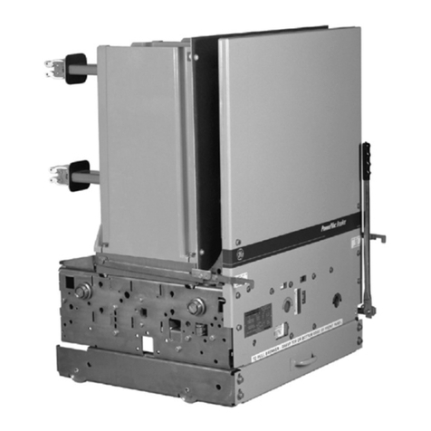
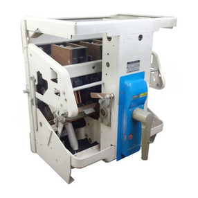
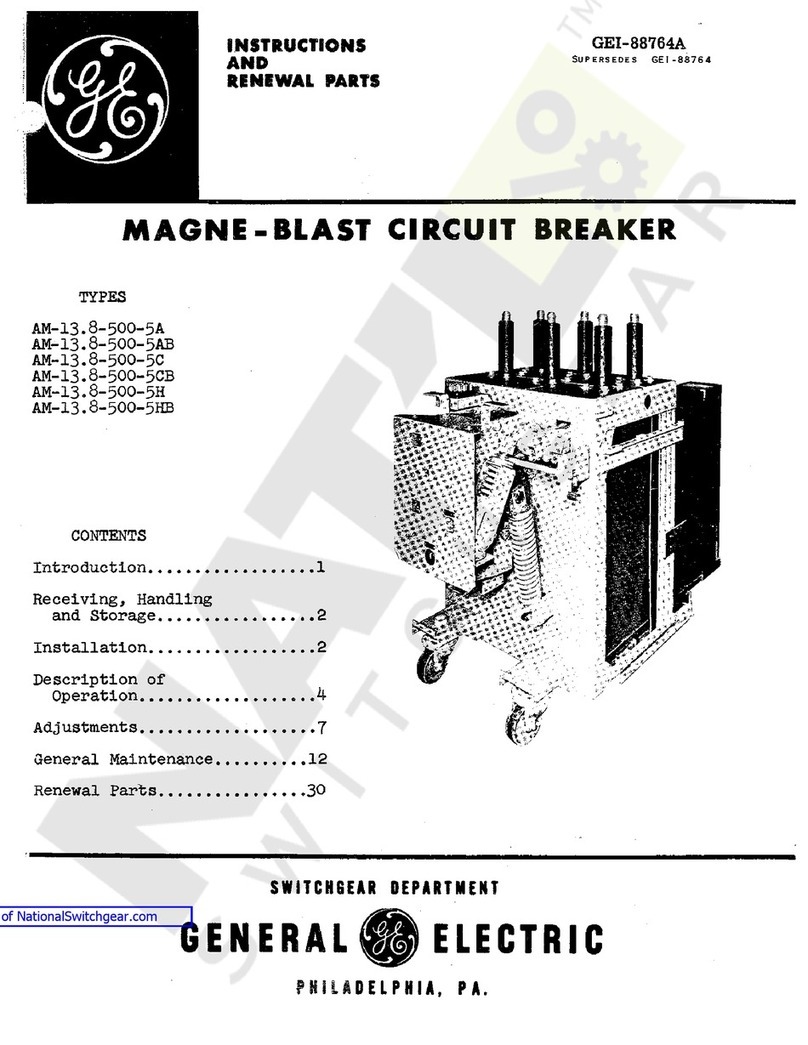
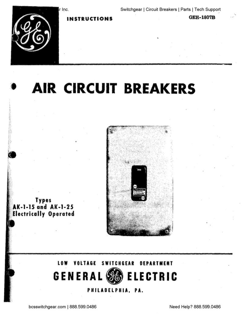
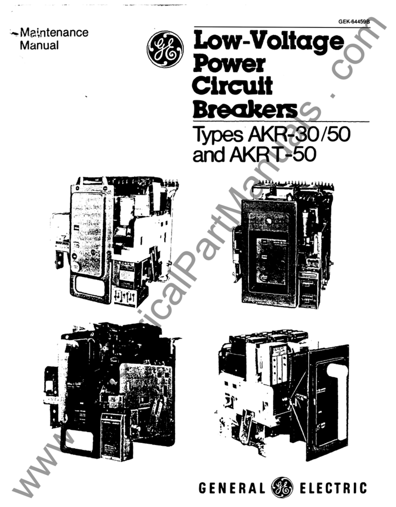
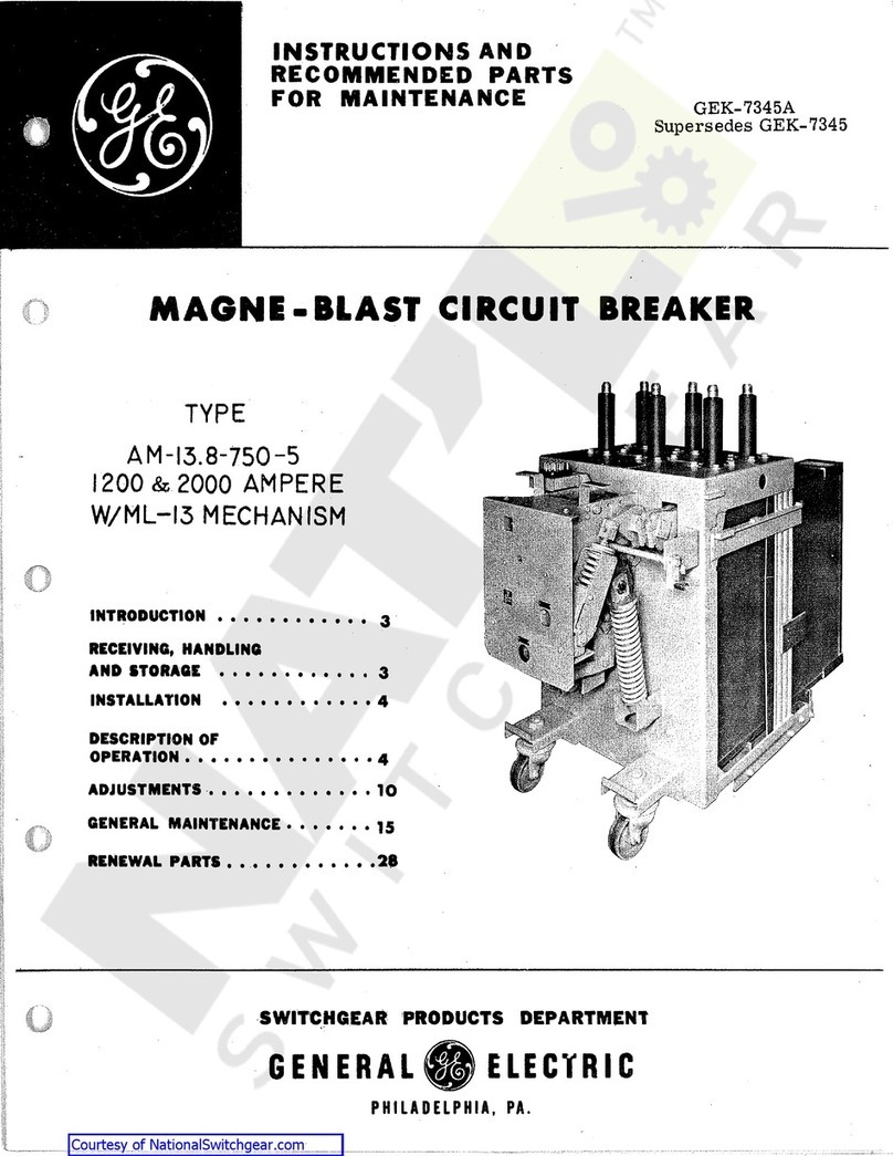
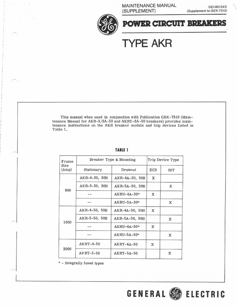
GE AK-15 User manual

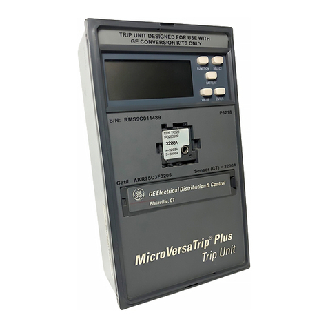
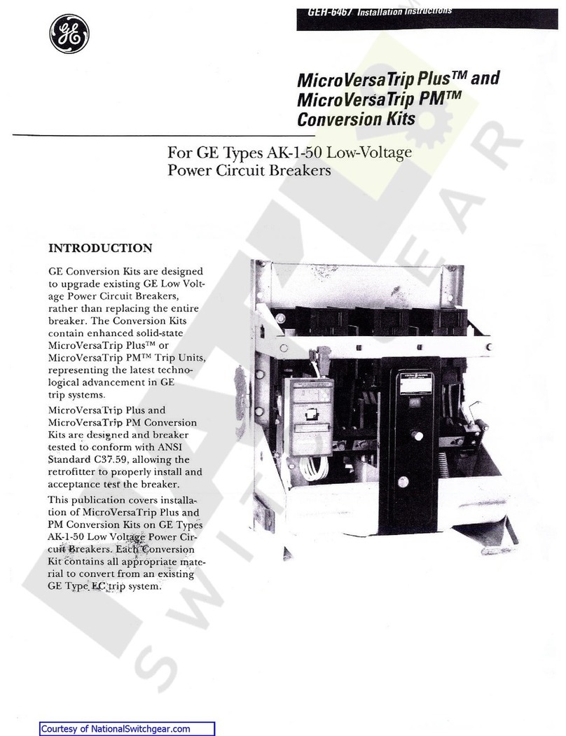
MicroVersaTrifP
Plus
and
PM
Conversion
Kits
For
GE
Types
AK
-
15
,
AK
-
25
,
AKU
-
25
,
AKR
-
30
S
,
AKRU
-
30
S
Low
Voltage
Power
Circuit
Breakers
Introduction
GE
Conversion
Kits
are
designed
to
upgrade
existing
GE
Low
Voltage
Power
Circuit
Breakers
,
rather
than
replace
,
the
entire
breaker
.
The
Conversion
Kits
contain
enhanced
solid
-
state
Micro
VersaTrip
-
Plus
or
Micro
VersaTrip
35
PM
trip
units
,
representing
the
latest
technological
advancements
in
GE
trip
systems
.
Micro
VersaTrip
1
Plus
and
Micro
VersaTrip
3
PM
Conversion
Kits
are
designed
and
breaker
-
tested
to
conform
with
ANSI
standard
C
37.59
,
allowing
the
retrofitter
to
properly
install
and
acceptance
test
the
breaker
.
This
publication
covers
installation
of
MicroVersaTrip
-
Plus
and
Micro
VersaTrip
35
PM
Conversion
Kits
on
GE
types
AK
-
15
,
.
AK
-
25
,
AKU
-
25
,
AKR
-
30
S
,
AKRU
-
30
S
Low
Voltage
Power
Circuit
Breakers
.
Each
Conversion
Kit
contains
all
ap
-
propriate
material
to
convert
from
an
existing
EC
Power
Sensor
,
ECS
or
SST
trip
system
,
or
upgrade
Micro
VersaTrip
and
Micro
VersaTrip
RMS
-
9
trip
systems
.
Courtesy of NationalSwitchgear.com

TABLE
OF
CONTENTS
n
3
GENERAL
INFORMATION
SECTION
1
3
SECTION
2
PRIOR
TO
INSTALLATION
4
-
12
SECTION
3
FRONT
FRAME
BREAKER
CONVERSION
Separating
the
Breaker
Remounting
X
and
Y
Relays
Installing
the
Flux
Shifter
Installing
the
Programmer
Bracket
Installing
the
Programmer
Harness
Installing
the
Communications
Harness
4
5
-
6
7
-
8
9
10
11
-
12
13
-
16
13
-
16
SECTION
4
BACK
FRAME
BREAKER
CONVERSION
Installing
Phase
Sensors
17
-
20
SECTION
5
FOUR
-
WIRE
GROUND
FAULT
OPTION
Drawout
Breakers
Stationary
Breakers
Installing
Neutral
Sensors
17
18
19
-
20
I
21
-
23
EQUIPMENT
CONVERSION
Stud
Shield
Modification
Remounting
Primary
Disconnect
Fingers
Installing
the
Insulator
Bracket
and
Wire
Harness
SECTION
6
21
22
23
SECTION
7
INSTALLING
THE
PROGRAMMER
24
25
-
27
TESTING
AND
TROUBLESHOOTING
Cabling
Diagrams
SECTION
8
27
Q
2
Courtesy of NationalSwitchgear.com

SECTION
1
GENERAL
INFORMATION
programmable
trip
unit
have
been
furnished
.
Whenever
the
ground
fault
trip
element
is
fur
-
nished
for
breakers
applied
on
4
-
wire
systems
,
note
that
an
associated
neutral
sensor
(
CT
)
is
required
for
separate
mounting
in
the
equipment
.
Make
sure
that
retrofitted
breakers
are
applied
within
their
short
circuit
rating
.
For
example
,
when
the
trip
ele
-
ments
of
the
breaker
are
to
be
changed
from
long
-
time
,
instantaneous
to
long
-
time
,
short
-
time
,
the
short
-
time
rating
would
govern
the
application
.
As
a
service
-
related
consideration
,
the
installation
of
the
MicroVersaTrip
Plus
or
PM
kits
provides
an
excel
-
lent
opportunity
to
perform
normal
maintenance
on
the
breaker
,
particularly
when
the
front
and
back
frames
are
separated
.
Such
procedures
are
de
-
scribed
in
the
installation
and
maintenance
manu
-
als
supplied
with
the
Breakers
and
Equipment
.
GE
Conversion
Kit
installation
is
straightforward
,
but
does
require
careful
workmanship
and
atten
-
tion
to
these
instructions
.
Familiarity
with
the
breaker
itself
is
highly
desirable
.
The
general
ap
-
proach
is
to
first
strip
the
breaker
of
its
existing
trip
devices
,
then
install
the
MicroVersaTrip
®
Plus
or
PM
Kit
components
.
Following
this
procedure
,
the
con
-
verted
breaker
is
performance
tested
,
prior
to
re
-
storing
the
breaker
to
service
.
The
majority
of
breaker
kit
installations
do
not
re
-
quire
any
customized
assembly
work
.
However
,
some
conversions
may
involve
unusual
mounting
circumstances
or
accessory
combinations
which
ne
-
cessitate
minor
modification
and
/
or
relocation
of
a
component
(
s
)
.
In
most
instances
this
supplemen
-
tary
work
can
be
done
on
site
.
Preparatory
to
the
conversion
,
the
installer
should
verify
that
the
appropriate
current
sensors
and
SECTION
2
-
PRIOR
TO
INSTALLATION
Turn
off
and
lock
out
the
powder
source
feeding
the
breaker
prior
to
attempting
any
installation
,
maintenance
,
or
modification
.
Follow
all
lock
-
out
and
tagging
rules
of
the
National
Electrical
Code
and
all
other
applicable
codes
.
Do
not
work
on
a
closed
breaker
or
a
breaker
with
the
closing
springs
charged
.
Trip
OPEN
the
breaker
and
be
sure
the
stored
energy
springs
are
discharged
avoiding
the
possibility
that
the
breakers
may
trip
OPEN
or
the
charg
-
ing
springs
discharge
,
causing
injuries
.
For
both
stationary
and
draw
out
breakers
,
trip
OPEN
,
then
remove
the
breaker
to
a
well
lighted
work
area
before
beginning
work
.
Do
not
perform
any
maintenance
including
breaker
charging
,
closing
,
tripping
,
or
any
other
function
which
could
cause
significant
move
-
ment
of
the
breaker
while
it
is
on
the
draw
out
extension
rails
.
Do
not
leave
the
breaker
in
an
intermediate
po
-
sition
in
the
switchgear
compartment
.
Always
leave
it
in
the
CONNECTED
,
TEST
,
or
DIS
-
CONNECTED
position
.
Failure
to
do
so
could
lead
to
improper
positioning
of
the
breaker
and
flashback
.
Before
starting
any
work
,
turn
off
and
lock
out
all
power
sources
leading
to
the
breaker
(
primary
and
secondary
)
.
Remove
the
breaker
to
a
clean
,
well
lighted
work
area
.
WARNING
:
Low
Voltage
Power
Circuit
Break
-
ers
utilize
high
speed
,
stored
energy
spring
op
-
erating
mechanisms
.
The
breakers
and
their
enclosures
contain
interlocks
and
safety
fea
-
tures
intended
to
provide
safe
,
proper
operat
-
ing
sequences
.
For
maximum
personnel
pro
-
tection
associated
with
installation
,
operation
,
and
maintenance
of
these
breakers
the
follow
-
ing
procedures
must
be
followed
.
Failure
to
fol
-
low
these
procedures
may
result
in
personal
in
-
jury
7
or
property
damage
.
•
Only
qualified
persons
,
as
defined
in
the
Na
-
tional
Electrical
Code
,
who
are
familiar
with
the
installation
and
maintenance
of
low
voltage
power
circuit
breakers
,
and
switchgear
assem
-
blies
,
should
perform
any
work
associated
with
these
breakers
.
•
Completely
read
and
understand
all
instructions
before
attempting
any
breaker
installation
,
op
-
eration
,
maintenance
,
or
modification
.
3
Courtesy of NationalSwitchgear.com

SECTION
3
FRONT
FRAME
BREAKER
CONVERSION
The
front
frame
breaker
conversion
consists
of
the
following
:
1
.
Separation
of
the
front
and
back
breaker
frames
(
for
AK
-
15
and
AK
-
25
only
)
.
Refer
to
the
appro
-
priate
installation
and
maintenance
manuals
supplied
with
the
breakers
and
equipment
for
instruction
on
accomplishing
the
separation
.
Copies
of
these
publications
may
be
obtained
from
your
local
GE
sales
office
.
2
.
Remove
the
existing
trip
devices
.
3
.
On
electrically
operated
type
AK
-
2
-
25
and
AK
-
2
A
-
25
breakers
with
EC
trip
devices
,
relocating
and
remounting
the
x
and
y
relays
.
4
.
Installing
the
flux
shifter
and
trip
paddle
.
5
.
Installing
the
programmer
mounting
bracket
.
6
.
Installing
the
programmer
and
communications
wire
harness
.
Separating
the
Breaker
Frames
Verify
that
the
breaker
is
OPEN
,
then
perform
the
following
steps
:
Step
1
.
Remove
the
steel
arc
quencher
retainer
by
loosening
the
two
V
}
x
20
hex
capnuts
.
On
electrically
operated
AK
-
3
/
3
A
-
25
breakers
,
the
Y
re
-
lay
is
mounted
on
the
left
end
of
the
retainer
so
there
is
no
need
to
remove
it
.
On
AK
-
3
/
2
A
-
25
breakers
,
it
is
mounted
on
the
right
side
and
will
have
to
be
moved
to
the
left
side
.
The
steps
are
shown
on
page
5
.
Step
2
Remove
the
three
arc
quenchers
by
lifting
upward
and
outward
.
Step
3
.
Separate
the
breaker
’
s
front
and
back
frames
.
(
refer
to
the
appropriate
maintenance
manuals
)
Remove
the
Existing
Trip
Devices
Step
1
.
Remove
the
overcurrent
trip
devices
.
Step
2
.
On
draw
out
breakers
,
remove
the
primary
disconnect
fingers
from
the
bottom
(
load
-
side
)
copper
studs
.
Step
3
.
Remove
the
three
bottom
(
load
side
)
copper
stud
assemblies
.
On
Powder
Sensor
equipped
breakers
,
this
will
have
been
done
during
Step
1
.
Step
4
.
On
EC
equipped
breakers
,
remove
and
discard
the
four
trip
device
support
brackets
mounted
along
the
low
:
er
front
of
the
back
frame
.
See
Fig
.
3
-
1
.
At
this
point
the
breaker
back
frame
is
ready
for
instal
-
lation
of
the
Conversion
Kit
components
provided
.
4
Courtesy of NationalSwitchgear.com

SECTION
3
FRONT
FRAME
BREAKER
CONVERSION
Remounting
X
and
Y
Relays
On
electrically
operated
breakers
equipped
with
EC
trip
device
,
the
Y
relay
is
mounted
on
the
front
frame
at
the
right
side
of
the
operation
mechanism
.
Step
1
.
To
provide
mounting
space
for
the
new
flux
shift
trip
device
,
remove
the
Y
relay
and
remount
it
on
the
left
end
of
the
arc
quencher
retainer
as
shown
in
Figs
.
3
-
2
and
3
-
3
(
using
hardware
and
parts
included
)
.
Step
2
.
Modify
the
breaker
'
s
wiring
harness
to
suit
.
The
X
relay
should
be
remounted
after
the
programmer
mount
and
bracket
are
installed
.
See
installing
the
programmer
bracket
and
Fig
.
3
-
8
.
Fig
.
3
-
2
.
Right
Side
View
of
Front
Frame
5
Courtesy of NationalSwitchgear.com

SECTION
3
FRONT
FRAME
BREAKER
CONVERSION
Remounting
X
and
Y
Relays
(
Cont
’
d
)
ON
AK
-
2
-
25
/
2
A
-
25
ELECTRICAL
BREAKERS
,
REMOVE
AND
RELOCATE
“
Y
”
REIAYTO
.
ARC
QUENCHER
RETAINER
.
NEW
LOCATION
OF
“
Y
”
REI
AY
i
0
t
9
0
0
B
n
m
i
i
OPEN
I
I
_
—
-
r
J
I
l
'
—
•
«
I
l
I
l
I
j
1
*
I
II
0
I
I
TRIP
I
mu
,
—
I
ll
o
I
.
CLOSE
1
u
I
1
=
d
1
X
/
.
i
A
A
ROUTE
WIRE
HARNESS
“
X
”
SO
THAT
IT
WILL
BE
TRAPPED
BY
THIS
WIRE
KEEPER
.
vTTfWWu
LOCATION
OF
MAGNETIC
TRIP
DEVICE
ON
AK
-
3
-
25
/
3
A
-
25
MODELS
.
0
0
WIRE
HARNESS
“
X
”
CONNECT
TO
PROGRAMMER
HARNESS
CONNECTOR
.
ON
AKD
DRAW
OUT
BREAKER
MFG
.
PRIOR
TO
1969
CUT
OFF
THE
RACK
-
IN
ARM
DOTTED
SECTION
TO
CLEAR
PROGRAMMER
.
SOCKET
TERMINAL
CAUTION
-
ROUTE
HARNESS
“
X
”
SO
THAT
IT
WILL
NOT
BE
CUT
BY
MOVING
PARTS
OF
THE
CLOSING
SOLENOID
.
Fig
.
3
-
3
.
Front
View
of
Front
Frame
(
AKD
Type
Draw
7
Out
Shown
)
6
Courtesy of NationalSwitchgear.com

SECTION
3
FRONT
FRAME
BREAKER
CONVERSION
FLUX
SHIFTER
Installing
the
Flux
Shifter
The
Flux
Shifter
trip
device
is
mounted
to
the
right
of
the
operating
mechanism
as
shown
in
Fig
.
3
-
6
.
Step
1
.
Remove
the
existing
flux
shifter
device
.
Step
2
.
Mount
the
flux
shifter
trip
paddle
on
the
breaker
'
s
trip
shaft
per
Figs
.
3
-
6
and
3
-
8
.
Pushing
the
draw
out
locking
lever
in
will
allow
the
trip
bar
to
rotate
to
an
easily
accessible
point
.
Step
3
.
Install
the
flux
shifter
actuating
bushing
in
the
right
hand
operation
link
,
enlarging
the
link
hole
if
nec
-
essary
.
See
Fig
.
3
-
8
.
Step
4
.
Mount
the
flux
shifter
assembly
to
the
right
side
of
the
front
frame
as
shown
in
Fig
.
3
-
6
.
On
Power
Sensor
breakers
equipped
with
shunt
trip
,
mount
the
flux
shifter
on
top
of
the
shunt
trip
bracket
.
If
no
shunt
trip
is
installed
,
use
the
54
"
spacer
provided
(
Fig
.
3.7
)
.
Step
5
.
When
the
flux
shifter
and
its
trip
paddle
are
installed
and
the
front
and
back
breaker
frames
are
reassembled
,
the
following
adjustment
must
be
made
.
Note
that
the
back
frame
must
be
converted
first
.
With
the
breaker
in
the
OPEN
position
and
the
mechanism
fully
charged
,
set
the
gap
between
the
trip
paddle
and
the
end
of
the
flux
shifter
trip
rod
at
.
093
to
.
125
inches
.
Use
a
0.100
-
inch
diameter
rod
(
not
supplied
)
as
shown
in
Fig
.
3
-
8
.
Set
the
adjuster
end
of
the
trip
rod
and
lock
it
in
place
with
the
jam
nut
.
OPTIONAL
TEST
:
The
flux
shifter
assembly
may
be
tested
by
closing
the
breaker
and
applying
a
9
V
dc
powder
source
to
the
flux
shifter
leads
.
The
red
wire
is
the
positive
lead
.
The
breaker
should
trip
.
TRIP
PADDLE
Fig
.
3
-
6
.
Rear
View
of
Front
Frame
Showing
Location
of
Trip
Paddle
for
Flux
Shift
Trip
Device
Fig
.
3
-
7
.
Side
View
of
Flux
Shifter
Installed
*
Trademark
of
the
Loctite
Corp
.
7
Courtesy of NationalSwitchgear.com

SECTION
3
FRONT
FRAME
BREAKER
CONVERSION
Installing
the
Flux
Shifter
(
Cont
’
d
)
AFTER
BREAKER
IS
REASSEMBLED
ADJUST
THE
FLUX
SHIFT
TRIP
ROD
AS
FOLLOWS
:
WITH
BREAKER
OPEN
AND
THE
TRIPSHAFT
RESET
,
TURN
.
ADJUSTER
UNTIL
GAP
IS
.
093
TO
.
125
,
THEN
LOCK
WITH
JAM
NUT
.
INSERTED
ACTUATING
BUSHING
WHEN
REASSEMBLING
THE
FRONT
AND
BACK
FRAMES
ENGAGE
BUSHING
(
IN
RH
OPER
.
LINK
)
WITH
OPERATING
LEVER
OF
THE
FLUX
SHIFT
TRIP
DEVICE
AS
SHOWN
.
RIGHT
SIDE
OF
MECHANISM
FRAME
VIEWED
FROM
REAR
OF
FRONT
FRAME
.
RIGHT
OPER
.
LINK
W
JAM
NUT
v
ADJUSTER
P
C
h
-
TRIP
PADDLE
ON
EC
EQUIPPED
BREAKERS
IT
WILL
BE
NECESSARY
TO
DRILL
AND
TAP
OR
BOLT
THIS
#
10
-
32
HOLE
IN
THE
FRONT
FRAME
USE
THE
FLUX
SHIFT
TRIP
DEVICE
BRACKET
.
AS
TEMPLATE
.
ON
POWER
SENSOR
BREAKERS
EQUIPPED
WITH
SHUNT
TRIP
,
MOUNT
FLUX
SHIFT
TRIP
DEVICE
ON
TOP
OF
THE
SHUNT
TFUP
BRACKET
.
IF
NO
SHUNT
TRIP
,
USE
SPACER
PROVIDED
.
Fig
.
3
-
8
.
Right
Side
View
of
Mechanism
Frame
Showing
Mounting
of
Flux
Shift
Trip
Device
8
Courtesy of NationalSwitchgear.com

SECTION
3
FRONT
FRAME
BREAKER
CONVERSION
Installing
the
Programmer
Bracket
The
MicroVersaTrip
®
Plus
or
PM
programmer
mounts
to
the
lower
right
side
of
the
breaker
.
Step
1
.
Assemble
the
programmer
shock
mount
bracket
to
the
programmer
support
bracket
per
Fig
.
3
-
9
.
Step
2
.
Mount
the
X
relay
on
the
bracket
using
(
3
)
#
10
screws
and
lock
washers
provided
,
see
Fig
.
3
-
9
.
Step
3
.
Modify
the
X
relay
harness
by
adding
16
gauge
ex
-
tension
wire
,
splices
and
ring
terminals
provided
.
Work
one
wire
at
a
time
.
Route
the
wires
as
shown
in
Fig
.
3
-
10
,
making
certain
that
they
do
not
inter
-
fere
with
the
solenoid
plunger
or
programmer
.
Fig
.
3
-
10
.
X
Relay
Wire
Routing
—
FRONT
FRAME
1
o
o
I
D
£
'
\
1
I
I
I
I
LTJ
_
ft
>
I
0
'
~
'
L
w
)
51
I
I
[
.
y
!
_
o
/
!
-
T
-
~
J
7
NEW
LOCATION
\
TRIP
UNIT
BRACKET
PROGRAMMER
SUPPORT
BRACKET
“
X
”
RELAY
Fig
.
3
-
9
.
Right
Side
View
Showing
Mounting
Position
of
Programmer
Unit
9
Courtesy of NationalSwitchgear.com

SECTION
3
FRONT
FRAME
BREAKER
CONVERSION
NOTE
LOCATION
OF
BEVELED
EDGES
ON
PLUG
BODY
Installing
the
Programmer
Harness
The
programmer
harness
consists
of
the
mating
36
-
pin
programmer
connector
and
the
associated
wiring
.
Step
1
.
Assemble
the
adapter
bracket
to
the
36
-
pin
pro
-
grammer
connector
(
with
bevels
to
right
side
)
by
pushing
the
bracket
over
the
notches
in
ends
of
plug
body
(
Step
1
)
.
Follow
Steps
2
through
5
of
Fig
.
3
-
11
to
complete
assembly
of
programmer
harness
to
programmer
bracket
.
-
^
Jooooooooo
'
I
*
—
Voooo
ooooo
r
1
0
loooooooooi
0
foooo
000
0
0
,
1
ADAPTER
BRACKET
STEP
1
.
PUSH
BRACKET
OVER
NOTCHES
IN
END
OF
PLUG
BODY
&
1
STEP
5
.
HOLD
PLUG
BODY
TIGHT
TO
THE
ADAPTER
BRACKET
AND
BEND
OVER
(
2
)
LOCKING
TABS
CAUTION
:
The
adapter
bracket
must
be
installed
onto
harness
plug
as
shown
in
Fig
.
3
-
11
.
Failure
to
do
so
will
result
in
harness
plug
failure
and
pro
-
grammer
will
not
provide
any
protection
.
STEP
3
.
PRESS
ON
PUSH
NUTS
UNTIL
BRACKET
IS
HELD
FIRMLY
AGAINST
PROGRAMMER
BRACKET
V
4
00000000
oooooooo
oooooooo
oooooooo
,
Step
2
.
Plug
the
4
-
pin
wiring
harness
connector
into
the
mating
plug
on
the
flux
shifter
assembly
.
NOTE
:
The
current
sensor
leads
can
be
connected
after
the
front
and
back
frames
are
joined
.
PIN
1
STEP
4
.
HOLD
PLUG
FIRMLY
BEND
LOCKING
TABS
STEP
2
.
PULL
WIRE
HARNESS
BRACKET
ASSEMBLY
UP
OVER
GUIDE
PINS
AND
PUSH
ALL
THE
WAY
DOWN
m
^
GUIDE
PINS
'
-
a
Fig
.
3
-
11
.
Programmer
Harness
Connector
Fig
.
3
-
12
.
Programmer
Plate
Installation
10
Courtesy of NationalSwitchgear.com

SECTION
3
FRONT
FRAME
BREAKER
CONVERSION
CAUTION
Installing
the
Communications
Harness
(
When
Required
)
The
communication
harness
should
be
installed
on
the
breaker
compartment
’
s
door
hinge
side
,
to
pro
-
tect
it
from
damage
when
operating
the
compart
-
ment
door
.
Fig
.
3
-
13
and
3
-
15
show
the
mounting
and
installation
sequence
for
AK
-
15
and
25
break
-
ers
.
A
caution
label
,
Fig
.
3
-
14
,
should
be
mounted
on
the
breaker
and
the
compartment
door
as
a
warning
to
prevent
unnecessary
damage
.
DISCONNECT
SECONDARY
BEFORE
REMOVING
BREAKER
.
Fig
.
3
-
14
.
Caution
Label
Fig
.
3
-
15
.
AK
-
25
/
AKR
-
30
S
Communications
Harness
Installation
Fig
.
3
-
13
.
AK
-
15
/
25
Harness
Installation
11
Courtesy of NationalSwitchgear.com

SECTION
3
FRONT
FRAME
BREAKER
CONVERSION
e
)
Installing
the
Communications
Harness
(
When
Required
)
cont
’
d
Fig
.
3
-
16
shows
the
drill
and
mounting
hole
pattern
for
AKR
-
30
S
series
breakers
.
For
this
type
of
breaker
with
a
4
th
wire
disconnect
device
,
the
communica
-
tion
harness
must
be
mounted
on
the
left
hand
side
.
Hole
locations
given
are
for
reference
only
.
The
communications
disconnect
plug
location
should
be
determined
by
a
field
engineer
during
job
assessment
.
)
v
^
'
Fig
.
3
-
15
.
AKR
-
30
S
Harness
Installation
.
)
12
Courtesy of NationalSwitchgear.com

SECTION
4
BACK
FRAME
BREAKER
CONVERSION
MOVABLE
CONTACT
PIVOT
SUPPORT
REUSE
HARDWARE
Installing
Phase
Sensors
(
CPs
)
w
.
.
/
Phase
sensor
modification
for
the
AK
-
15
and
AK
-
25
circuit
breakers
is
completed
by
mounting
the
three
current
sensor
assemblies
to
the
back
frame
.
See
Fig
.
4
-
1
,
4
-
2
,
and
4
-
3
.
Step
1
.
Insert
lower
copper
stud
through
the
back
plate
and
attach
it
via
the
mounting
screw
.
Step
2
.
Position
the
CT
with
its
terminal
toward
the
rear
and
loosely
mount
it
to
the
stud
with
copper
,
90
°
angled
bus
strap
and
the
bolt
provided
.
Step
3
.
Align
the
assembly
,
then
torque
the
two
%
"
bolts
in
the
strap
to
250
in
.
-
lbs
.
each
to
assure
proper
contact
integrity
.
Step
4
.
Install
the
CT
terminal
board
-
mounting
bracket
be
-
low
the
CTs
using
the
(
2
)
8
-
32
x
Vi
'
screws
pro
-
vided
.
See
Fig
.
4
-
3
.
Mount
terminal
boards
TB
1
,
TB
2
,
and
TB
3
to
the
bracket
using
the
(
6
)
6
-
32
x
Vi
screws
and
washers
provided
.
Step
5
.
Reassemble
the
front
and
back
frames
.
REUSE
HARDWARE
Ml
IJl
-
—
INSULATOR
MODIFIED
REUSE
HARDWARE
I
l
\
S
\
\
\
\
\
W
\
\
3
1
^
i
r
I
i
i
LJ
O
I
LOWER
STUE
BACK
PI
ATE
CURRENT
SENSOR
Fig
.
4
-
1
.
Phase
Sensor
Assembly
,
Right
Side
View
Step
6
.
The
wiring
harness
can
be
connected
to
the
CTs
only
after
the
front
and
back
frames
have
been
joined
.
Fig
.
4
-
4
shows
a
converted
back
frame
and
the
wiring
connections
as
they
will
look
after
joined
.
NOTE
:
Ocassionally
,
during
current
sensor
manufacturing
,
a
slight
separation
occurs
of
the
epoxy
from
the
plastic
shell
.
This
may
amount
to
as
much
as
0.030
"
and
has
no
effect
on
per
-
formance
.
Additionally
,
slight
surface
imperfec
-
tions
are
part
of
the
epoxy
curing
process
and
have
no
effect
on
performance
.
13
Courtesy of NationalSwitchgear.com

SECTION
4
BACK
FRAME
BREAKER
CONVERSION
Installing
Phase
Sensors
(
CT
’
s
)
Cont
’
d
Phase
sensor
modification
for
the
AKR
-
30
S
circuit
breakers
is
as
follows
:
Step
1
.
Remove
the
3
/
8
"
bolt
holding
the
top
copper
bus
stop
to
the
contact
arm
.
See
Fig
.
4
-
5
.
Step
2
.
Loosen
the
1
/
4
"
bolt
holding
the
same
copper
strap
to
the
round
CT
post
.
Slide
the
strap
off
the
post
.
See
Fig
.
4
-
5
.
Step
3
.
Replace
the
CT
with
the
MicroVersaTrip
®
CT
provided
with
the
kit
.
The
terminals
should
point
down
.
Step
4
.
Reassemble
the
copper
bus
removed
in
steps
1
&
2
.
See
Fig
.
4
-
6
.
Fig
.
4
-
5
.
Removal
of
the
Phase
Sensors
on
AKR
-
30
S
Breakers
NOTE
:
Ocassionally
,
during
current
sensor
manufacturing
,
a
slight
separation
occurs
of
the
epoxy
from
the
plastic
shell
.
This
may
amount
to
as
much
as
0.030
M
and
has
no
effect
on
per
-
formance
.
Additionally
,
slight
surface
imperfec
-
tions
are
part
of
the
epoxy
curing
process
and
have
no
effect
on
performance
.
)
5
i
Fig
.
4
-
6
AKR
-
30
S
Breaker
with
MicroVersaTrip
®
Phase
Sensors
.
U f
)
16
Courtesy of NationalSwitchgear.com

SECTION
5
FOUR
-
WIRE
GROUND
FAULT
OPTION
DRAW
OUT
BREAKERS
Step
1
.
Mount
the
neutral
sensor
disconnect
block
to
the
rear
of
the
back
frame
per
Fig
.
5
-
1
.
Use
existing
mounting
holes
.
Step
2
.
Feed
the
end
of
the
harness
through
the
hole
“
X
”
in
the
back
frame
and
connect
leads
to
the
block
.
The
MicroVersaTrip
®
Plus
and
PM
Ground
Fault
option
requires
an
additional
neutral
sensor
when
used
on
a
four
-
wire
system
having
its
neutral
grounded
at
the
transformer
.
The
phase
sensors
are
mounted
on
the
breaker
.
However
,
the
neutral
sensor
is
inserted
in
the
neutral
bus
,
which
is
part
of
the
equipment
.
The
neutral
sensor
is
connected
to
the
breaker
through
the
4
th
-
wire
neutral
disconnect
.
Wire
harness
installation
depends
on
whether
the
breaker
is
a
4
-
wire
draw
out
or
a
4
-
wire
stationary
system
.
HARNESS
HOLE
“
X
"
FRONT
VIEW
OF
BACK
FRAME
—
WHITE
COM
REAR
OF
BACK
FRAME
HOLE
“
X
”
>
°
o
1.38
o
W
LOO
4.75
.
APPROX
.
REF
SIDE
VIEW
REAR
VIEW
OF
BACK
FRAME
Fig
.
5
-
1
.
Mounting
Detail
for
Secondary
Disconnect
Block
for
4
th
Wire
Neutral
Sensor
(
Draw
Out
Breakers
Only
)
17
Courtesy of NationalSwitchgear.com

SECTION
5
FOUR
-
WIRE
GROUND
FAULT
OPTION
Installing
Neutral
Sensors
(
when
required
)
The
neutral
sensor
is
an
electrical
duplicate
of
the
phase
sensor
,
including
the
taps
,
therefore
,
when
taps
(
if
provided
)
are
changed
on
the
phase
sen
-
sors
,
the
taps
on
the
neutral
sensor
must
be
corre
-
spondingly
positioned
.
For
kits
with
Fixed
phase
sen
-
sors
,
be
sure
to
use
the
corresponding
tap
on
the
neutral
sensor
.
The
following
modifications
are
required
only
in
conjunction
with
breakers
being
equipped
with
4
-
wire
Ground
Fault
trip
elements
.
Step
1
.
Mount
the
neutral
sensor
(
CT
)
in
the
outgoing
neutral
lead
,
normally
in
the
equipment
’
s
bus
or
cable
compartment
.
See
Fig
.
5
-
3
for
the
sensor
’
s
bar
drilling
plan
.
Check
to
insure
that
the
neutral
and
phase
sensors
match
,
i
.
e
.
,
have
the
same
ampere
range
.
Step
2
.
Connect
the
neutral
sensor
to
the
disconnect
block
per
wiring
instructions
of
Fig
.
5
-
4
.
For
stationary
breakers
,
the
neutral
sensor
is
connected
to
TB
5
.
Fig
.
5
-
3
.
Neutral
Sensor
Outline
19
Courtesy of NationalSwitchgear.com

SECTION
5
FOUR
-
WIRE
GROUND
FAULT
OPTION
Installing
Neutral
Sensors
(
Cont
’
d
)
NOTE
:
BOND
ON
LINE
SIDE
ONLY
VARIABLE
TAP
TERMINAL
BLOCK
*
#
14
MIN
.
WIRE
,
WIRES
MUST
BE
RUN
TOGETHER
AND
TIED
TO
PREVENT
LOOPS
LINE
NEUTRAL
CT
TAP
TYPICAL
TERMINAL
100
FT
MAX
‘
*
LOAD
A
A
TAP
COM
c
TERMINAL
STRAPS
TAP
COM
4
TH
-
WIRE
NEUTRAL
SENSOR
STATIONARY
DISCONNECT
BLOCK
SPRING
LOADED
BUTT
CONTACTS
Fig
.
5
-
4
.
Connecting
the
4
th
Wire
Neutral
Sensor
20
Courtesy of NationalSwitchgear.com
This manual suits for next models
4
Table of contents
Other GE Circuit Breaker manuals

GE
GE EntelliGuard L User manual

GE
GE MicroVersaTrip Plus Series User manual

GE
GE SPST480 User manual

GE
GE GL 310 F3/4031 P/VR User manual

GE
GE ML-14-0 User manual

GE
GE M-Pact Plus User manual

GE
GE AKR User manual

GE
GE MicroVersaTrip Plus User manual

GE
GE Magne-Blast AM-13.8-1000-3H User manual

GE
GE Power Break II User manual

GE
GE Power Break II User manual

GE
GE Power Break II User manual

GE
GE MicroVersaTrip AKR-75 User manual

GE
GE GL 311 F3/4031 P/VE User manual

GE
GE Power Break II User manual

GE
GE Shunt Trip User manual

GE
GE Rapid TripFix User manual

GE
GE AK-2-15 User manual

GE
GE SD200SA User manual
GE
GE A Series Pro-Stock TQD User manual