DISPATCH AND STORAGE 9
1.1 Condition on delivery
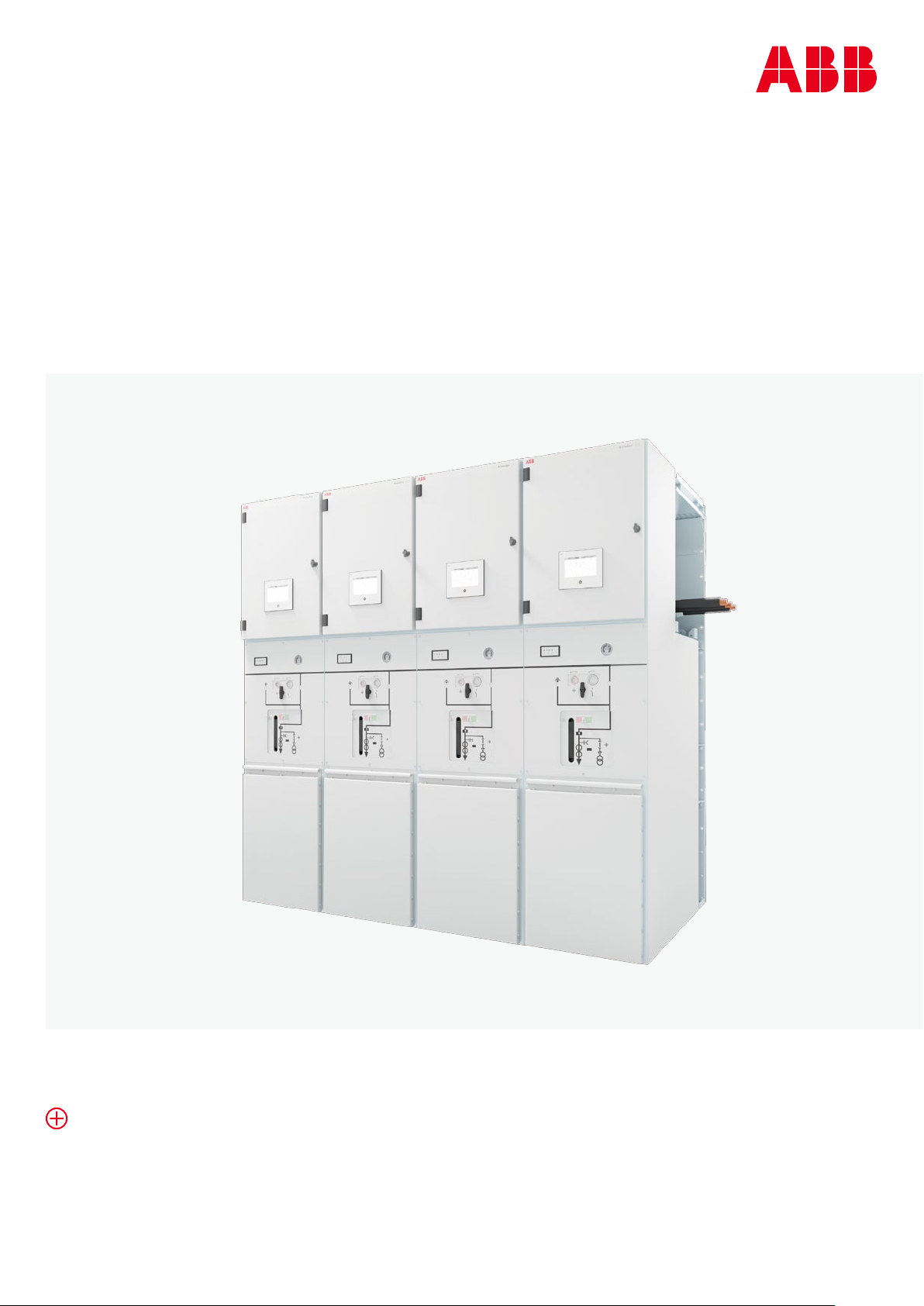
The panels have been routine tested to IEC 62271-200
| GB 3906.
•In normal cases, the gas compartments have
been filled with insulating gas to the rated filling
pressure. When airfreighted, however, the panels
are delivered with reduced pressure.
•If airfreight with PrimeGear ZX0 panels is needed,
please contact ABB for further guidance.
•The individual parts of the busbars, the installation
material and accessories and the documentation
are packaged separately from the panels.
When the busbars are removed from the
packaging, do not lay them on their
silicone surfaces. As the copper is very
heavy, the silicone can be damaged even
if the components are incorrectly stored
for a short period only. Always use the
spacers supplied for storage.
1.2 Delivery
Check the consignment for completeness and
freedom from damage. Document any transport
damage found on the waybill and inform us of it
immediately. Take photographs of the damage.
1.3 Packaging
The panels have been prepared for transport by
the agreed method and for the desired duration
of any interim storage required. Details of the
length of preservation and the storage location
(indoors or outdoors) can be found in the order
documents. If the panels are packaged, they are
mounted on a pallet and secured to prevent them
from slipping.
The possible packaging methods are as follows:
•No packaging.
•Packaged in plastic sheeting.
•Packaged in plastic sheeting and surrounded by
protective cardboard.
•Heat sealed in plastic sheeting with drying
agent enclosed.
•Packaged in aluminum foil in transport crate
with drying agent enclosed.
1.4 Handling
The transport units are the panels.
Always handle the panels in the upright
position.
Take account of the weight of the transport
units when selecting the handling
equipment.
Due to the high centre of gravity of the
panels, there is a risk that the transport
units may tip over! Take all precautions to
protect personnel and the materials
transported. When using hydraulic lift
trolleys to transport panels of 450 mm
width or during positioning of the panels
on the foundation rails, there is a high risk
of them tipping. Therefore always fit lateral
support plates as shown in Fig. 1.4.3.1 to
prevent them from doing so.
Only ever handle the panels by
•forklift truck.
•trolley jack.
•crane, or.
•hydraulic lift trolley (Support plates required for
panels of 450 mm width!).
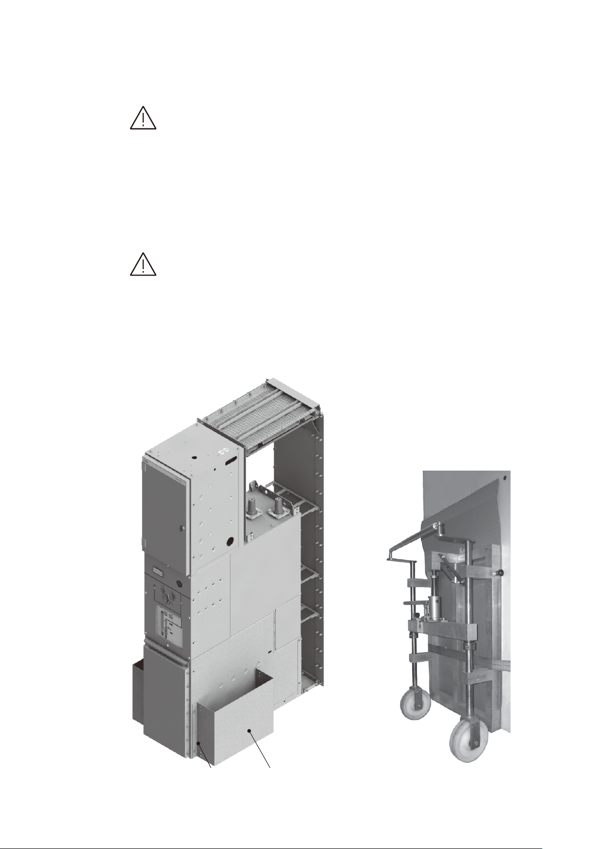
1.4.1 Handling by forklift truck or trolley jack
The panels must each be mounted on a
pallet and secured with straps. The pallet
must rest fully on the forks of the truck
or jack. The high centre of gravity means
there is a high risk of tipping. Avoid jerky
motions.
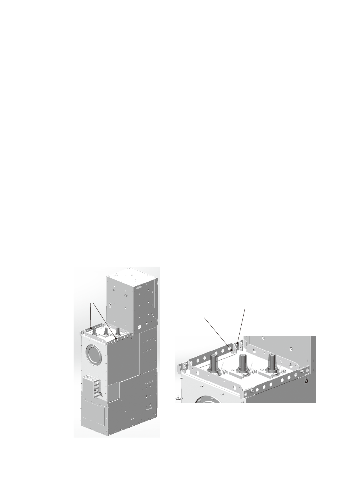
1.4.2 Handling by crane
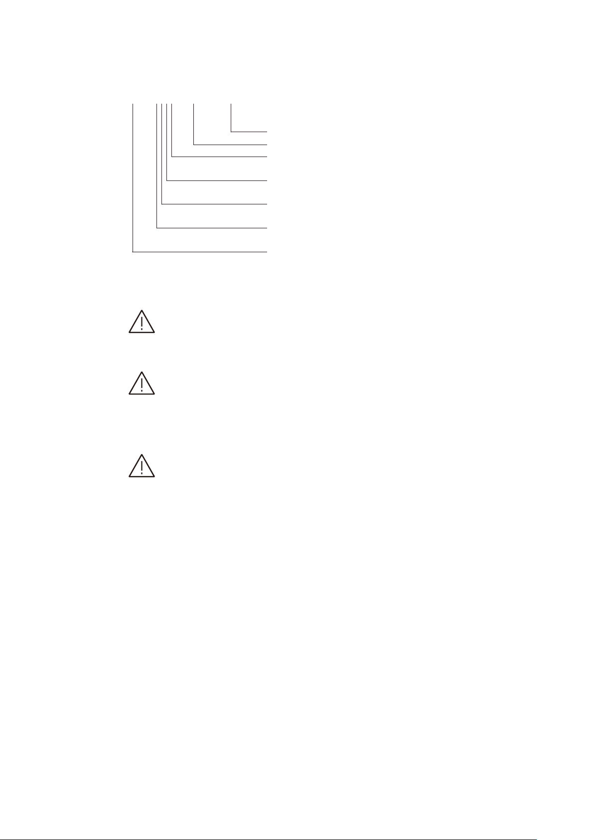
•As shown in Fig.1.4.2.1, fasten one lifting
bracket each to the left and right of the roof
section and U shape parts of the panel module,
using two M12 X 30 cheese-headscrews with
dished washers & nuts and three M8 dished
washer & nuts in each case.
•Attach suspension ropes of a sufficient load
bearing capacity (see section 11, Technical data,
for the panel weights) and sufficient length to
the lifting brackets using shackles thread the
suspension ropes through the cutouts in the
rope guides. The ABB scope of supply does not
include suspension ropes and shackles.
Lifting brackets
M8 dished washers & Nuts
M12x30 cheese-head screw
with dished washers & nut
—
Fig. 1.4.2.1: Preparing a
panel for handling by
crane
—
Fig. 1.4.2.1