Taylor-Dunn B0-T48-48 Taylor Truck T48 User manual

The Best Way
To Go
About Your
Business
®
Serial number Starting: 149242
MANUAL MB-T48-01
Operation, Troubleshooting and Re-
placement Parts Manual
Models Inlcuded:
B0-T48-48 Taylor Truck (T48)
ET-030-48 (ET 3000)
Revision: F
Taylor Truck
ET 3000


TAYLOR-DUNN SERVICE CENTER
For more information about this and other Taylor-Dunn manuals, please write:
Taylor-Dunn Mfg.
2114 W. Ball Road
Anaheim, CA 92804
(Attn: Technical Writer)
COPYRIGHT NOTICE
Copyright © 2001 by Taylor-Dunn Mfg. All rights reserved.
No part of this work may be reproduced or transmitted in any form or by any means, electronic
or mechanical, including photocopying and recording, or any information storage or retrieval
system without prior written permission of Taylor-Dunn Mfg. unless such copying is
expressly permitted by federal copyright law. Address inquiries to Reference Permissions,
Taylor-Dunn Mfg., 2114 W. Ball Road, Anaheim, CA 92804


TABLE OF CONTENTS
INTRODUCTION
Operator and Maintenance Manual
Introduction ................................................................. ii
How To Use This Manual ....................................................... iii
Who Should Read This Manual ............................................... iv
Responsibilities ....................................................................... iv
Conventions.............................................................................. v
SECTION 1
Vehicle Description and Specifications
Vehicle Description ...................................................... 2
Standard Specifications ............................................................. 3
Taking Delivery of the Vehicle ................................................. 4
What To Do If a Problem Is Found ........................................... 6
SECTION 2
Safety Rules and Operational Information
Safety Rules and Guidelines....................................... 2
DRIVER TRAINING PROGRAM........................................... 4
DRIVER QUALIFICATIONS .................................................. 5
VEHICLE CONTROLS ........................................................... 6
Key-Switch ............................................................... 6
Forward-Reverse Switch........................................... 6
Accelerator................................................................ 6
Steering..................................................................... 7
Foot Brake ................................................................ 7
Park Brake ................................................................ 7
Horn Button .............................................................. 7
Seat Interlock Switch ................................................ 8
Headlights and Accessories (Optional) Switch ......... 8
Hour Meter ............................................................... 8
Charger Interlock ....................................................... 8
Battery Status Indicator............................................. 9
Reverse and Motion Alarm ........................................ 9
Electrolyte Alarm (Optional) ...................................... 9
Windshield Washer Fluid Tank .................................. 9
Smart View Display ................................................. 10
Smart View Display Fault Codes ............................. 11
Vehicle Operational Guidelines ................................................ 13
Driving ..................................................................... 13
Loading and Unloading............................................. 13
Parking ..................................................................... 13
Towing ..................................................................... 13
Storing and Returning to Service .............................................. 14
Returning To Service ................................................ 14

SECTION 3
Maintenance and Service Procedures
Maintenance Guidelines ............................................. 2
Severe Duty Guidelines............................................... 3
Periodic Maintenance Checklist................................. 4
Lubrication Chart ......................................................... 5
Troubleshooting Guide ................................................ 6
Brakes ....................................................................................... 7
Brake Pad Replacement ............................................ 9
Repairing the Brake Body....................................... 10
Bleeding the Brakes ................................................ 12
Replacing the Master Cylinder ............................... 14
Filling and Checking the Fluid Level...................... 15
Parking Brake ......................................................................... 16
Parking Brake Adjustment ...................................... 17
Front Axle and Yokes.............................................................. 18
Axle Removal and Installation ................................ 19
Aligning the Front End ........................................... 20
Centering the Steering ............................................ 21
Repairing the Front Axle......................................... 22
Steering Yoke/Bushings .......................... 22
Ball Joints, Tie Rods, and Drag Links .................... 24
Front Wheel Bearings ............................................. 25
Adjusting Wheel Bearings........................ 26
Removal And Installation of the Steering Gear ....... 27
Steering Gear Adjustment ....................................... 29
Endplay ................................................... 29
Gear Lash ................................................ 30
Steering Gear Disassembly and Repair ................... 31
Drive Service........................................................................... 35
Removing the Rear Axles ........................................ 36
Removing and Installing the Drive ........................... 38
Disassembly and Reassembling of Primary
Reduction Gear Case............................................... 39
Disassembly of the 3rd Member ............................ 42
Assembly of the 3rd Member .................................. 45
Pinion Gear Shimming............................................. 48
Pinion Bearing Preload ............................................ 49
Changing the Differential Oil .................................. 50
Speed Controller ...................................................................... 51
Removing and Installing Speed Controller ............... 52
Drive Motor ........................................................................... 53
Motor Removal ...................................................... 54
Automatic Electric Brake Removal and Installation .55
Motor Disassembly and Assembly.......................... 57
Armature and Brush Inspection .............................. 59
Motor Specifications ............................................... 60
Battery ................................................................................... 61
Cleaning .................................................................. 62
Electrolyte Alarm ..................................................... 63
Servicing................................................................... 64
Charging .................................................................. 65
Battery Storage ....................................................... 65
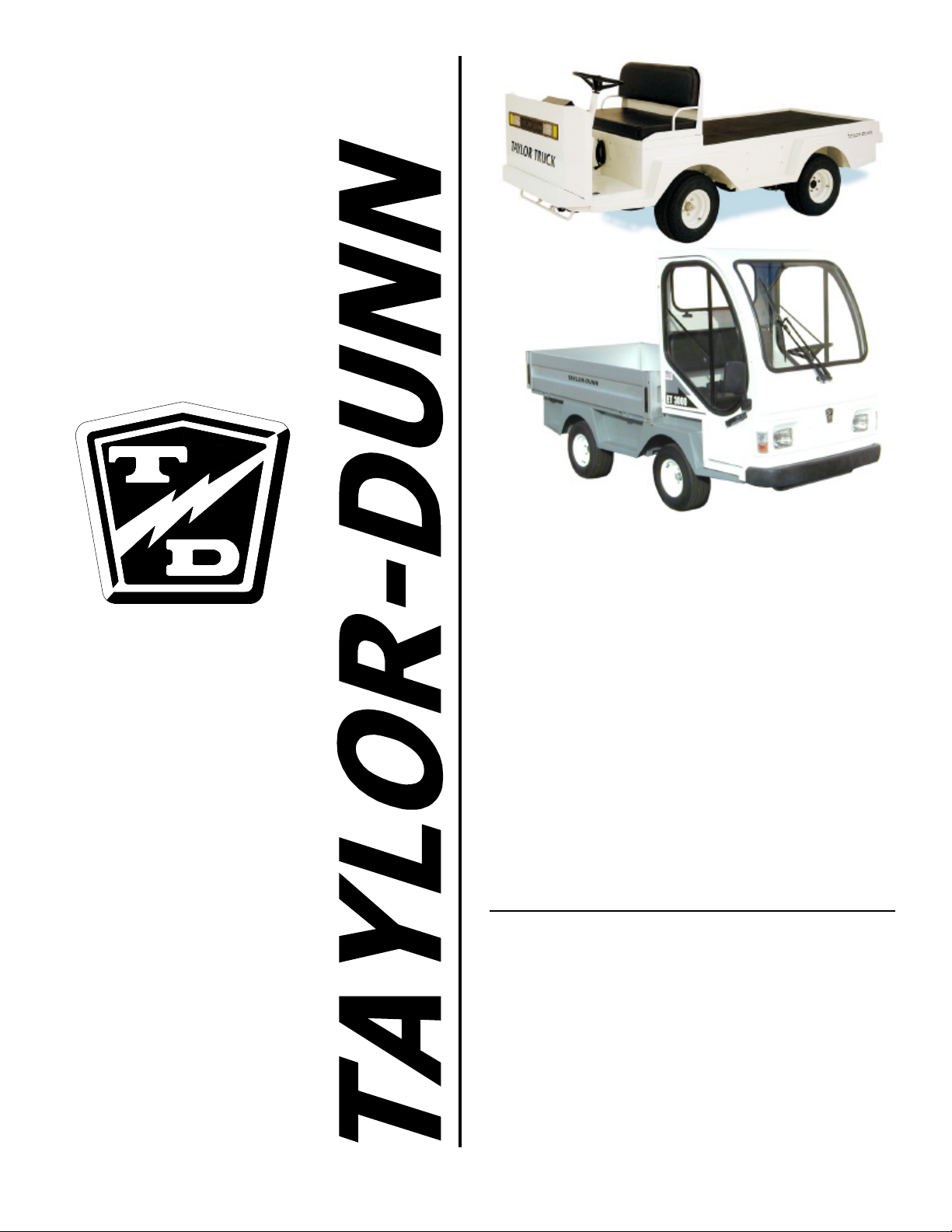
SECTION 4
ElectricalandCharger Troubleshooting
Sevcon Controller Troubleshooting ........................... 2
Voltage Reference Table........................................... 25
LED Status Chart ........................................................ 26
Lestronic II Charger Troubleshooting .........................1
Operating Instructions and Theory of Operation
Lester Lestronic II Battery Charger ................................... 2
Testing the Charging Cycle ........................................................ 3
Test Equipment Required .......................................................... 4
Troubleshooting for Built-In Charger ........................................ 5
Troubleshooting for Portable Charger........................................ 8
Testing the Timer Relay ............................................................ 9
Testing the interlock Relay ...................................................... 10
Signet Charger Troubleshooting .................................1
Operating Instructions and Theory of Operation ...................... 2
Testing the Charging Cycle ........................................................ 3
Test Equipment Required .......................................................... 4
Status LED Error Code.............................................................. 5
Troubleshooting......................................................................... 6
SECTION 4a
Wire Diagrams
Complete Vehicle......................................................... 2
Dash............................................................................... 3
Control panel................................................................ 4
Throttle Module .............................................................5
Lighting ..........................................................................6
SECTION 5
Illustrated Parts List
Common Front Axle Assembly.................................................... 2
Steering Sleeve Assembly .......................................... 4
Front Suspension ......................................................... 6
Drag Link ...................................................................... 8
Steering Gear ............................................................. 10
Steering Column Assembly....................................... 12
Master Cylinder, Brake Line Hardware, and
Front Brake Assembly................................................ 14
Master Cylinder ........................................................... 16
Hydraulic Disc Brakes ................................................ 18
Parking Brake Linkage............................................... 20

Motor ........................................................................... 22
Automatic Electric Brake............................................24
Instrument Panel and Components...........................26
Resetting the Smart View Display.............................27
Control Panel .............................................................. 28
Electrical Components (typical) .................................30
Lester Charger.............................................................32
Signet Charger ............................................................34
Accelerator Module ....................................................36
Drive .............................................................................38
Drive Assembly............................................................ 42
Rear Axle .....................................................................44
Decals...........................................................................46
Hitch Optional Parts....................................................48
SECTION 5A
Illustrated Parts List
TaylorTruck Standard Parts
Tire & Wheel Assemblies, and
Tire & WheelComponents ..............................2
Optional Parts
Directional Signals and Strobe Light ...........4
Optional Parts
Cowl with Windshield, Cab, and
Windshield Wipers..........................................6
Optional Parts
Strobe Light on Steel Cab, Mirrors,
Dome Light, and Fiber Glass
Cab Bumper......................................................8
Surrey and Fiberglass Top Cover ..............................10
Door Options ................................................................12
Deck Boards.................................................................14
Box with Doors and Watering System Parts ........... 16
Stake Side Options .....................................................18

SECTION 5B
Illustrated Parts List
ET 3000 Standard Parts
Tire & Wheel Assemblies, and
Tire & WheelComponents ..............................2
Standard Parts ..............................................................4
Standard Parts
Cab Interior, Dash, and Seat Switch ..............6
Standard Parts, Aluminum Side Panel Option
and Deck Board Option ...................................8
Box with Doors ........................................................... 10
APPENDIX ASpecial Tools
APPENDIX BStandard Torque Values


INTRODUCTION
Operator and Maintenance Manual

INTRODUCTION PAGE ii
MB-T48-01
Introduction
The purchase of this vehicle shows a belief in high quality products
manufactured in the USA. Taylor-Dunn , a leading manufacturer of
electric burden and personnel carriers since 1949, wants to be
sure this vehicle provides years of reliable service. Please
continue to read this manual and
enjoy this high quality
Taylor-Dunn
vehicle.
This manual is to serve as a guide for the service,
repair, and operation of this Taylor-Dunn vehicle
and is not intended as a training guide. Taylor-
Dunn has made every effort to include as much
information as possible about the operation and
maintenance of its vehicles.
Included in this manual are:
• Vehicle Description
• Safety Rules and Guidelines
• Operational Information
• Operator Responsibilities
• Owner Responsibilities
• Control Operation and Location
Information
• Maintenance and Troubleshooting
Information
• Standard Parts List
Before servicing, operating,
training or performing
maintenance on this or any other
Taylor-Dunn vehicle, read the
appropriate Taylor-Dunn manual.
Each Taylor-Dunn manual
references the applicable models
and serial numbers on the front
cover.
Please, be aware of all cautions,
warnings, instructions, and notes
contained in this manual.

INTRODUCTION PAGE iii
MB-T48-01
How To Use This Manual
This manual is organized into five main sections:
SECTION 1: Vehicle Description and Specification
This section describes the vehicle and operation of this particular vehicle,
as well as the responsibilities of the operator.
SECTION 2: Safety Rules and Operational Information
This section outlines the safety and operational issues, location and
operation of controls, and the operational checks that are to be performed
on this vehicle. It also includes various subjects that should be included in
the operator and service training program.
SECTION 3: Maintenance and Repair
This section gives specific information on the servicing of the vehicle and
a schedule for maintenance checks.
SECTION 4: Electrical and Charger Troubleshooting
This section identifies the troubleshooting procedures for testing the
electrical system and battery charger.
SECTION 5: Illustrated Parts
This section provides an illustrated view of various assemblies. The
illustrations are accompanied by tables identifying the parts.

INTRODUCTION PAGE iv
MB-T48-01
Responsibilities
Of the Owner...
The owner of this or any Taylor-
Dunn vehicle is responsible for
the overall maintenance and
repairs of the vehicle, as well as
the training of operators. Owners
should keep a record of
conducted training and
maintenance performed on the vehicle. (OSHA Regulation, 29
CFR 1910.178 Powered Industrial Truck Operator Training).
Of the Operator...
The operator is responsible for the safe operation of the vehicle,
preoperational and operational checks on the vehicle, and the
reporting of any problems to service and repair personnel.
Of the Service Personnel...
The service personnel are responsible for the service and
maintenance of the vehicle. At no time should a service person
allow any untrained personnel to service or repair this or any
Taylor-Dunn vehicle. For the purposes of training, a qualified
service person may oversee the repairs or services being made
to a vehicle by an individual in training. At no time should an
untrained individual be allowed to service or repair a vehicle
without supervision. This manual is not a training guide.
Of the Passengers ...
The passengers are responsible to remain fully seated, keeping
their hands, arms, and legs inside the vehicle at all times. Each
passenger should be fully aware of the vehicle’s operation. All
forms of recklessness are to be avoided. Do not engage in
horseplay.
Who Should Read This Manual
This manual is intended for use by anyone who
is going to operate, own, perform maintenance
on, service, or order parts for this Taylor-Dunn
vehicle. Each person should be familiar with the
parts of this manual that apply to their use of
this vehicle.

INTRODUCTION PAGE v
MB-T48-01
An unshaded box with no symbols next to it will
contain infromation for completing tests.
Conventions
Symbols and/or words that are used to define warnings, cautions,
instructions, or notes found throughout this manual:
A shaded box with the word “Warning” on its left
denotes a warning. A warning alerts the reader
of a hazard that may result injury to themself or
others. Be sure to follow any instructions
contained within a warning and exercise extreme
care while performing the task.
The symbol at the left and the bold text contained
within a box denotes a “Caution” and is used to
inform the reader that property damage may
occur. Be sure to exercise special care and follow
any instructions contained with in a caution.
NOTE: Alerts the reader to additional information about a
subject.

INTRODUCTION PAGE vi
MB-T48-01

SECTION 1
Vehicle Description and Specifications

SECTION 1 PAGE 2
MB-T48-01
Vehicle Description
This vehicle is designed for driving on
smooth surfaces in and around industrial
plants, nurseries, institutions, motels,
mobile home parks, and resorts. It is not
intended for use on public highways.
Figure 1
Figure 2
This manual applies to the models and serial
numbers listed on the front cover.
This vehicle conforms to requirements
for Type E vehicles as described in
O.S.H.A. Standard Section 1910.178
(Powered Industrial Trucks) and with
all applicable portions of the American
National Standard for Personnel and
Burden Carriers (ANSI B56.8) in effect
at the time of manufacture.
The vehicle serial number is stamped in the
frame, behind the seat bulk head on the
forward deck bed angle (Figure 2).
The maximum operating speed of this vehicle is the speed that
it may travel on a level surface with no load. Exceeding this
speed may result in steering difficulty, motor damage, and or
loss of control of the vehicle that may result in personal injury
and/or property damage.
The model number for this vehicle is imprinted
on a decal located under the right side seat on
the top of the front inner fender (Figure 1).

SECTION 1 PAGE 3
MB-T48-01
Standard Specifications
ITEM SPECIFICATION
Occupancy 2 Passenger
Dimension Taylor Truck 318L X 127W X 119H Centimeters
125L X 50W X 47H Inches
ET 3000 325L X 127W X 191H Centimeters
128L X 50W X 75H Inches
Turning Radius 368 Centimeters
145 Inches
Dry Weight Taylor Truck 696 kg
1534 lbs
ET 3000 856 kg
1884 lbs
Maximum Load 1360 kg
3000 lbs
Electrical System 8-244 Amp HR., 6 Volt, Lead Acid Batteries
System Voltage 48 Volts
Controller Solid State, 500 Amp, 48 Volts
Transmission Helical Gear, Oil Bath,
Automotive Type Hypoid Differential.
Motor DC Separately Excited Field,
48V, 5.9kW, for 60 min
Speed (Unloaded) 18 mph
Brakes 4 Wheel Hydraulic Disc,
Park Brake, Hand Operated
Steering Automotive Steering 24:1
Tires 20.5 X 8 X 10 Load Range, E
Tire Pressure 90 psi max
Frame Steel Unitized Body
Heavy Duty 14 Gauge Smooth Skin Steel
Instrumentation Battery Discharge Indicator, Key Switch
Forward/Reverse Switch, Headlight Switch,
Hour Meter
Light Accessories Dual Headlights, Dual Tail/Brake Lights
ET 3000 Directional Turn Signals
Charger 115v AC, 15A 60Hz, 25 Amp DC, 48 Volt
Built-In Automatic

SECTION 1 PAGE 4
MB-T48-01
Taking Delivery of the Vehicle
Inspect the vehicle immediately after delivery. Use the following guidelines to
locate obvious problems:
•Examine the contents of all packages and
accessories that may have come in separate
packages with the vehicle.
• Make sure everything listed on the packing slip
is there.
• Check that all wire connections, battery cables,
and other electrical connections are secure.
• Check battery cells to be sure they are filled.
• Check the tire pressure, tightness of lug nuts,
and for any signs of damage.
Other manuals for B0-T48-48 Taylor Truck T48
2
This manual suits for next models
5
Table of contents
Other Taylor-Dunn Truck manuals
Popular Truck manuals by other brands

Komatsu
Komatsu 730E Operation & maintenance manual

Clarke
Clarke CPF300 Assembly instructions

Rail-Ability
Rail-Ability JCB 714 manual

Jungheinrich
Jungheinrich AMXE 10 operating instructions

Crown
Crown Stand-up Rider Lift Truck RC 5500 Series Operator's manual

Pfaff
Pfaff HU ES 10 A Translated Operating Instructions