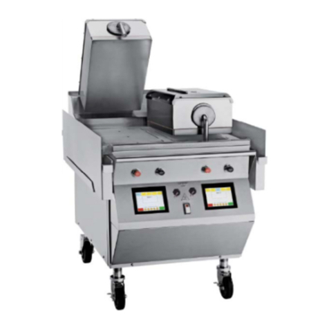
Taylor 810 Series Operating instructions

SERVICE
MANUAL
Model 810, 812, 820, 822, 828 Series
Auto Gap Grills
6/24/11 (Original Publication)
(Updated 6/11/2019)
Original Service Instructions
073523-S

CAUTION: Information in this manual is intended to be used by Taylor service technicians only.
Note: Continuing research results in steady improvements; therefore, information in this manual is subject to
change without notice.
Note: Only instructions originating from the factory or its authorized translation representative(s) are
considered to be the original set of instructions.
© 2011 Taylor Company
073523-S
Any unauthorized reproduction, disclosure, or distribution of copies by any person of any portion of this work may be a
violation of Copyright Law of the United States of America and other countries, could result in the awarding of Statutory
Damages of up to $250,000 (17 USC 504) for infringement, and may result in further civil and criminal penalties.
All rights reserved.
Taylor Company
750 N. Blackhawk Blvd.
Rockton, IL 61072

Table of Contents
073523-S i
Section 1: Introduction
Safety................................................................................................................. 1-2
General Installation Instructions......................................................................... 1-4
Environmental Notices ....................................................................................... 1-5
Model C810 Specifications................................................................................. 1-7
Model L810, G810 Specifications ...................................................................... 1-9
Model C812 Specifications............................................................................... 1-11
Model L812 Specifications ............................................................................... 1-13
Model C820 Specifications............................................................................... 1-15
Model L820, G820 Specifications .................................................................... 1-17
Model C822 Specifications............................................................................... 1-19
Model L822 Specifications ............................................................................... 1-21
Model L828, G828 Specifications .................................................................... 1-23
Patty Placement and Removal Guide .............................................................. 1-25
Section 2: Controls and Systems
Control Keys....................................................................................................... 2-2
Control Overview................................................................................................ 2-3
Controls.............................................................................................................. 2-4
Software Loading Procedures..........................................................................2-15
Electrical Power Distribution ............................................................................ 2-18
Amp Draw ........................................................................................................ 2-19
Gapping Procedures ........................................................................................2-24
Pneumatic System ........................................................................................... 2-26
Heating Elements............................................................................................. 2-27
Section 3: Troubleshooting
General Troubleshooting Guide......................................................................... 3-2
Error Messages.................................................................................................. 3-7
Troubleshooting Chart (Probe Open)................................................................. 3-9
Troubleshooting Chart (Probe Fail).................................................................. 3-10
Troubleshooting Chart (Clam Still Latched) .....................................................3-11
Troubleshooting Chart (Clam Did Not Latch) ................................................... 3-12
Meat Quality Troubleshooting .......................................................................... 3-13

ii 073523-S
Section 4: Parts
Warranty Explanation .........................................................................................4-2
Service Parts ......................................................................................................4-4
Accessories ......................................................................................................4-62
Section 5: Parts List
C810, L810, and G810 .......................................................................................5-2
C812 and L812 .................................................................................................5-15
C820, L820, and G820 .....................................................................................5-28
C822 and L822 .................................................................................................5-44
L828 and G828.................................................................................................5-54
Section 6: Wiring Diagrams
Model 810...........................................................................................................6-2
Model 812...........................................................................................................6-4
Model 820...........................................................................................................6-6
Model 822...........................................................................................................6-8
Model 828...........................................................................................................6-9

Section 1:
1-1
Model 810, 812, 820, 822, 828 Series
Introduction
Introduction
• Safety
• General Installation Instructions
• Environmental Notices
• Model C810 Specifications
• Model L810, G810 Specifications
• Model C812 Specifications
• Model L812 Specifications
• Model C820 Specifications
• Model L820, G820 Specifications
• Model C822 Specifications
• Model L822 Specifications
• Model L828, G828 Specifications
• Patty Placement and Removal Guide

1-2
INTRODUCTION
Model 810, 812, 820, 822, 828 Series Introduction
1
Safety
We at Taylor Company are deeply committed to
manufacturing safe operating and serviceable machines.
The many built-in safety features that are part of all
Taylor machines are aimed at protecting operators and
trained service technicians alike.
NOTICE! This manual is intended exclusively
for authorized Taylor service personnel.
NOTICE! DO NOT operate the machine before
reading the Operator's Manual. Failure to follow this
instruction may result in machine damage, poor machine
performance, health hazards, or personal injury.
IMPORTANT! In all areas of the world, the
machine should be installed in accordance with existing
local codes. Please contact your local authorities if you
have any questions.
Care should be taken to ensure that all basic safety
practices are followed during the installation and
servicing activities related to the installation and service
of Taylor®machines.
• Only authorized Taylor service personnel should
perform installation, maintenance, and repairs
on Taylor machines.
• Authorized service personnel should consult
OSHA Standard 29CFRI910.147 or the
applicable code of the local area for the industry
standards on lockout/tagout procedures before
beginning any installation or repairs.
• Authorized service personnel must ensure that
the proper personal protective equipment (PPE)
is available and worn when required during
installation and service.
•Authorized service personnel must remove all
metal jewelry, rings, and watches before
working on electrical equipment.
WARNING! Take caution to protect eyes,
lungs, and all parts of the body from potential harm when
using any chemical cleaner. Failure to follow this
instruction may result in a chemical burn.
CAUTION! Use extreme caution while setting
up, operating, and cleaning the machine to avoid coming
in contact with hot grill surfaces or with hot grease.
Failure to comply may result in burn injuries.
WARNING! This machine must be properly
grounded! DO NOT operate this machine unless it is
properly grounded and all service panels and access
doors are restrained with screws. Failure to do so can
result in severe personal injury from electrical shock!
WARNING! Avoid injury.
•DO NOT operate the machine with larger fuses
than specified on the data label.
•DO NOT attempt any repairs unless the power
supply to the machine has been disconnected.
Failure to follow these instructions may result in severe
personal injury from electrical shock.
WARNING! This machine has many sharp
edges that can cause severe injuries.
WARNING! This machine must NOT be
installed in an area where a water jet or hose can be
used. NEVER use a water jet or hose to rinse or clean
this machine. Using a water jet or hose on or around this
equipment may result in the electrocution of the user or
damage to the equipment.

INTRODUCTION
1-3
Model 810, 812, 820, 822, 828 Series
Introduction
1
CAUTION! This grill must be installed on a
level surface. Failure to comply may result in personal
injury or machine damage.
CAUTION!
•DO NOT store flammable vapors, liquids, or
combustible material in the vicinity of the
machine.
• Appropriate clearance must be maintained.
Failure to comply could result in a fire hazard.
WARNING! Only install this machine in a
location where its use and maintenance is restricted to
trained personnel. Failure to comply may result in
personal injury.

1-4
INTRODUCTION
Model 810, 812, 820, 822, 828 Series Introduction
1
General Installation Instructions
The following are general installation instructions. For
complete installation details, please see the checkout
card.
Site Preparation
Review the area where the machine is to be installed
before uncrating the machine. Make sure all possible
hazards to the user and the equipment have been
addressed.
For Indoor Use Only: This machine is designed to
operate indoors, under normal ambient temperatures of
70°F to 75°F (21°C to 24°C). The machine has
successfully performed in high ambient temperatures of
104°F (40°C) at reduced capacities.
CAUTION! This machine must be installed on
a level surface to avoid the hazard of tipping. Extreme
care should be taken in moving this machine for any
reason. Two or more people are required to safely move
this machine. Failure to comply may result in personal
injury or equipment damage.
When uncrating the machine, inspect the machine for
damage. Report any damage to your Taylor distributor.
This machine is made in the USA and has USA sizes of
hardware. All metric conversions are approximate and
vary in size.
Electrical Connections
The grill has two electrical connections. Check the data
plate on the grill for voltage, cycle, phase, and electrical
specifications. The power connections are located
behind the access line cover on the rear of the control
box under the front staging side of the grill.
In the United States, this equipment is intended to be
installed in accordance with the National Electrical Code
(NEC), ANSI/NFPA 70-1987. The purpose of the NEC
code is the practical safeguarding of persons and
property from hazards arising from the use of electricity.
This code contains provisions considered necessary for
safety. Compliance therewith and proper maintenance
will result in an installation essentially free from hazard.
In all other areas of the world, equipment should be
installed in accordance with the existing local codes.
Please contact your local authorities.
The proper wire size and fused circuit should be selected
according to grill data label information. Incoming power
must be connected to the terminals with black characters
on a white background.
WARNING! This machine must be properly
grounded! DO NOT operate this machine unless it is
properly grounded and all service panels and access
doors are restrained with screws. Failure to do so can
result in severe personal injury from electrical shock!
IMPORTANT! This machine is provided with a
grounding lug that is to be properly attached to the rear of
the frame by the authorized installer. The installation
location is marked by the equipotential bonding symbol
(5021 of IEC 60417-1) on the removable panel and the
frame.
NOTICE! Machines that are permanently
connected to fixed wiring and for which leakage currents
may exceed 10 mA, particularly when disconnected, not
used for long periods, or during initial installation, shall
have protective devices, such as a GFI, to protect against
the leakage of current, installed by the authorized
personnel to the local codes.
NOTICE! Stationary machines which are not
equipped with a power cord and a plug or another device
to disconnect the appliance from the power source must
have an all-pole disconnecting device with a contact gap
of at least 0.12 in. (3 mm) installed in the external
installation.

INTRODUCTION
1-5
Model 810, 812, 820, 822, 828 Series
Introduction
1
IMPORTANT! Supply cords used with this
machine shall be oil-resistant, sheathed flexible cable,
not lighter than ordinary polychloroprene or other
equivalent synthetic elastomer-sheathed cord (code
designation 60245 IEC 57). They must be installed with
the proper cord anchorage to relieve conductors from
strain, including twisting, at the terminals and protect the
insulation of the conductors from abrasion.
DANGER! The main power supply(s) must be
disconnected prior to performing any repairs. Failure to
follow this instruction may result in personal injury or
death from electrical shock or hazardous moving parts as
well as poor performance or damage to the equipment.
Note: Grills require electrical power for operation. In the
event of a power outage, place the machine in the OFF
position.
WARNING! This machine must NOT be
installed in an area where a water jet or hose can be
used. NEVER use a water jet or hose to rinse or clean
this machine. Using a water jet or hose on or around this
equipment may result in the electrocution of the user or
damage to the equipment.
Ventilation and Clearance
To ensure proper operation of this machine, it must be
installed away from all combustible products.
CAUTION! Allow for proper clearance and
airflow. Failure to comply may result in poor performance,
damage to the machine and create an unsafe operating
condition.
CAUTION! After setup, do not store anything
on top of the grill. Failure to follow this instruction may
result in a fire hazard.
WARNING! This machine must be isolated
from all combustible construction and materials including
but not limited to walls, partitions, furniture, floors,
curtains, paper, boxes, and decorations. Failure to
comply may result in fire and cause destruction and
severe injury.
Grease Disposal Container
In order to comply with NSF Standard 4 requirements, an
appropriate grease disposal container must be provided.
This container is supplied by the KES, not the Taylor
Company.
Environmental Notices
IMPORTANT! If the crossed-out waste
container symbol is affixed to this machine, it signifies
that this machine is compliant with the EU Directive as
well as other similar legislation in effect after August 13,
2005. Therefore, it must be collected separately after its
use is completed and cannot be disposed as unsorted
municipal waste. The user is responsible for delivering
the product to the appropriate collection facility, as
specified by your local code.

1-6
INTRODUCTION
Model 810, 812, 820, 822, 828 Series Introduction
1
this part is above the limit requirement of GB/T 26572.
(Fittings and hardware)
(Labels and insulations)
(Thermistors/Transducers)
(Circuit breaker and contactors)
(Coil assembly)
(Other metal
Hazardous Substances
Part Name
China RoHS2
(Pb) (Hg) (Cd) (Cr (VI)) (PBB) (PBDE)
(Sheet metal parts) OO O O O O
parts) OO O O O O
(Plastic parts) OO O O O O
OO O O O O
(Air Compressor) OO O O O O
OO O O O O
(Transformer) OO O O O O
OO O O O O
(Cable/Adaptor) OO O O O O
OO O O O O
(PCBA’s) OO O O O O
XOO O O O
(Bushings and bearings) XOO O O O
SJ/T 11364
O:GB/T 26572
X:GB/T 26572
This table is prepared in accordance with the provision of SJ/T 11364.
O: Indicates that said hazardous substance contained in all of the homogeneous materials for this
part is below the limit requirement of GB/T 26572.
X: Indicates that said hazardous substance contained in at least one of the homogeneous material for

INTRODUCTION
1-7
Model 810, 812, 820, 822, 828 Series
Introduction
1
Model C810 Specifications
See the data label for exact specifications.
Electrical
Standard is 208/60/3 phase.
Two dedicated electrical connections are required. See
the Electrical Chart for the proper electrical requirements.
The grill is manufactured to be permanently connected.
Consult your local Taylor distributor for receptacle
specifications, as local codes allow.
Table 1-1
**Plug supplied by customer.
Other electrical characteristics may be available.
(For exact electrical information, see the data label of the
machine.)
Dimensions
Width: 40-5/16 in. (1024 mm)
Depth: 38-13/16 in. (986 mm)
Height: 50-1/2 in. to 55-1/2 in. (1283 mm to 1410 mm)
Cooking Surface Height: 29 in. to 34 in. (737 mm to
864 mm)
Floor Clearance: 5-3/16 in. to 10-3/16 in. (132 mm to
259 mm)
(Casters may be adjusted.)
Approximate Weight
Net: 870 lb. (394.6 kg)
Crated: 997 lb. (452.2 kg)
Volume
53.7 cu. ft. (1.52 cu. m)
Electrical Amp per
Cord
Cord Supplied with NEMA
Plug
208/60/3 38 (2) NEMA 15-50P (2)
240/60/3 38 (2) NEMA 15-50P (2)
400/50/3 18 (2) **
400/50/3 13 (3) **

1-8
INTRODUCTION
Model 810, 812, 820, 822, 828 Series Introduction
1
C810 Specifications (Continued)
Figure 1-1
FIGURES IN BRACKETS INDICATE MILLIMETERS / DECIMAL AND FRACTIONAL DIMENSIONS EQUAL TO ( PLUS OR MINUS 1/16 IN. [1.5 MM])
MACHINE HEIGHT CAN VARY ( PLUS OR MINUS 2.5 IN. [63.5 MM] ) WITH CastER HEIGHT ADJUSTMENT / SIDE GREASE CANS NOT SHOWN.

INTRODUCTION
1-9
Model 810, 812, 820, 822, 828 Series
Introduction
1
Model L810, G810 Specifications
See the data label for exact specifications.
Electrical
Standard is 208/60/3 phase.
Two dedicated electrical connections are required. See
the Electrical Chart for the proper electrical requirements.
The grill is manufactured to be permanently connected.
Consult your local Taylor distributor for receptacle
specifications, as local codes allow.
Table 1-2
*Weighted platen model available voltage.
**Plug supplied by customer.
Other electrical characteristics may be available.
(For exact electrical information, see the data label of the
machine.)
Dimensions
Width: 40-5/16 in. (1024 mm)
Depth: 38-13/16 in. (986 mm)
Height: 55 in. to 60 in. (1397 mm to 1524 mm)
Cooking Surface Height: 29 in. to 34 in. (737 mm to
864 mm)
Floor Clearance: 5-3/16 in. to 10-3/16 in. (132 mm to
259 mm)
(Casters may be adjusted.)
Approximate Weight
Net: 870 lb. to *1040 lb. (394.6 kg to 465.7 kg)
Crated: 1035 lb. to *1205 lb. (469.4 kg to *546.6 kg)
(*weighted platen model)
Volume
53.7 cu. ft. (1.52 cu. m)
Electrical Amps per
Cord Total kW Cord Supplied with
NEMA Plug
208/60/3* 38 (2) 25 NEMA 15-50P (2)
240/60/3 33 (2) 27 NEMA 15-50P (2)
200/50/60/3 37 (2) 25 NEMA 15-50P (2)
400/50/3N~* 18 (2) 22.5 **
400/50/3N~ 13 (3) 22.5 **
230/400/60/
3N~
19 (2) 22.5 **

1-10
INTRODUCTION
Model 810, 812, 820, 822, 828 Series Introduction
1
L810, G810 Specifications (Continued)
Figure 1-2
FIGURES IN BRACKETS INDICATE MILLIMETERS / DECIMAL AND FRACTIONAL DIMENSIONS EQUAL TO ( PLUS OR MINUS 1/16 IN. [1.5 MM])
MACHINE HEIGHT CAN VARY ( PLUS OR MINUS 2.5 IN. [63.5 MM] ) WITH CastER HEIGHT ADJUSTMENT / SIDE GREASE CANS NOT SHOWN.

INTRODUCTION
1-11
Model 810, 812, 820, 822, 828 Series
Introduction
1
Model C812 Specifications
See the data label for exact specifications.
Electrical
Standard is 208/60/3 phase.
Two dedicated electrical connections are required. See
the Electrical Chart for the proper electrical requirements.
The grill is manufactured to be permanently connected.
Consult your local Taylor distributor for receptacle
specifications, as local codes allow. The restraining cable
is included.
208 Volt includes: Two, 7 ft. (2134 mm) electrical cords
and two plugs
Table 1-3
**Plug supplied by customer.
Other electrical characteristics may be available.
(For exact electrical information, see the data label of the
machine.)
Dimensions
Width: 40-5/16 in. (1024 mm)
Depth: 38-13/16 in. (986 mm)
Height: 50-1/2 in. to 55-1/2 in. (1283 mm to 1410 mm)
Cooking Surface Height: 29 in. to 34 in. (737 mm to
864 mm)
Floor Clearance: 5-3/16 in. to 10-3/16 in. (132 mm to
259 mm)
(Casters may be adjusted.)
Approximate Weight
Net: 773 lb. (351 kg)
Crated: 900 lb. (408 kg)
Volume
53.7 cu. ft. (1.52 cu. m)
Electrical Amp per
Cord
Cord Supplied with NEMA
Plug
208/60/3 38 (2) NEMA 15-50P (2)
220-240/50/3 34 (2) NEMA 15-50P (2)
400/50/3N~ 18 (2) * *

1-12
INTRODUCTION
Model 810, 812, 820, 822, 828 Series Introduction
1
C812 Specifications (Continued)
Figure 1-3
FIGURES IN BRACKETS INDICATE MILLIMETERS / DECIMAL AND FRACTIONAL DIMENSIONS EQUAL TO ( PLUS OR MINUS 1/16 IN.[1.5 MM])
MACHINE HEIGHT CAN VARY ( PLUS OR MINUS 2.5 IN. [63.5 MM] ) WITH CastER HEIGHT ADJUSTMENT / SIDE GREASE CANS NOT SHOWN.

INTRODUCTION
1-13
Model 810, 812, 820, 822, 828 Series
Introduction
1
Model L812 Specifications
See the data label for exact specifications.
Electrical
Standard is 208/60/3 phase.
Two dedicated electrical connections are required. See
the Electrical Chart for the proper electrical requirements.
The grill is manufactured to be permanently connected.
Consult your local Taylor distributor for receptacle
specifications, as local codes allow. The restraining cable
is included.
208 Volt includes: Two, 7 ft. (2134 mm) electrical cords
and two plugs
Table 1-4
**Plug supplied by customer.
Other electrical characteristics may be available.
(For exact electrical information, see the data label of the
machine.)
Dimensions
Width: 40-5/16 in. (1024 mm)
Depth: 38-13/16 in. (986 mm)
Height: 55 in. to 60 in. (1397 in. to 1524 mm)
Cooking Surface Height: 29 in. to 34 in. (737 mm to
864 mm)
Floor Clearance: 5-3/16 in. to 10-3/16 in. (132 mm to
259 mm)
(Casters may be adjusted.)
Approximate Weight
Net: 773 lb. (351 kg)
Crated: 947 lb. (430 kg)
Volume
53.7 cu. ft. (1.52 cu. m)
Electrical Amp per
Cord
Total
kW
Cord Supplied with
NEMA Plug
208/60/3 38 (2) 23 NEMA 15-50P (2)
240/60/3 33 (2) 27 NEMA 15-50P (2)
400/50/3N~ 18 (2) 20 * *

1-14
INTRODUCTION
Model 810, 812, 820, 822, 828 Series Introduction
1
L812 Specifications (Continued)
Figure 1-4
FIGURES IN BRACKETS INDICATE MILLIMETERS / DECIMAL AND FRACTIONAL DIMENSIONS EQUAL TO ( PLUS OR MINUS 1/16 IN. [1.5 MM])
MACHINE HEIGHT CAN VARY ( PLUS OR MINUS 2.5 IN. [63.5 MM] ) WITH CastER HEIGHT ADJUSTMENT / SIDE GREASE CANS NOT SHOWN.

INTRODUCTION
1-15
Model 810, 812, 820, 822, 828 Series
Introduction
1
Model C820 Specifications
See the data label for exact specifications.
Electrical
Standard is 208/60/3 phase.
One dedicated electrical connection is required. See the
Electrical Chart for the proper electrical requirements.
The grill is manufactured to be permanently connected.
Consult your local Taylor distributor for receptacle
specifications, as local codes allow.
Table 1-5
**Plug supplied by customer
Other electrical characteristics may be available.
(For exact electrical information, see the data label of the
machine.)
Dimensions
Width: 28-3/16 in. (716 mm)
Depth: 38-13/16 in. (986 mm)
Height: 50-1/2 in. to 55-1/2 in. (1283 mm to 1410 mm)
Cooking Surface Height: 29 in. to 34 in. (737 mm to
864 mm)
Floor Clearance: 6-3/4 in. to 11-3/4 in. (172 mm to
299 mm)
(Casters may be adjusted.)
Approximate Weight
Net: 670 lb. (304 kg)
Crated: 751 lb. (341 kg)
Volume
53.7 cu. ft. (1.52 cu. m)
Electrical Amp Cord Supplied with
NEMA Plug
208/60/3 48 NEMA 15-60P
220-240/50/3 44 NEMA 15-60P
240/60/3 43 NEMA 15-60P
400/50/3N~ 26 **
400/50/3N~ 14(2) **

1-16
INTRODUCTION
Model 810, 812, 820, 822, 828 Series Introduction
1
C820 Specifications (Continued)
Figure 1-5
FIGURES IN BRACKETS INDICATE MILLIMETERS / DECIMAL AND FRACTIONAL DIMENSIONS EQUAL TO ( PLUS OR MINUS 1/16 IN. [1.5 MM])
MACHINE HEIGHT CAN VARY ( PLUS OR MINUS 2.5 IN. [63.5 MM] ) WITH CastER HEIGHT ADJUSTMENT / SIDE GREASE CANS NOT SHOWN.
Other manuals for 810 Series
1
This manual suits for next models
4
Table of contents
Other Taylor Grill manuals

Taylor
Taylor QS12 User manual

Taylor
Taylor QS10 User manual

Taylor
Taylor C842 Installation manual

Taylor
Taylor C801 User manual

Taylor
Taylor 811 series User manual

Taylor
Taylor The Biggest Loser AG-1300-BL User manual

Taylor
Taylor C819 User manual

Taylor
Taylor C820 User manual

Taylor
Taylor The Biggest Loser AG-1300-BL User manual

Taylor
Taylor C850 Technical Document