POWERING POSITIVE CHANGE
MAXEON SOLAR TECHNOLOGIES, LTD.
Safety and Installation Instructions - Document 539821 Rev.D
© 2023 Maxeon Solar Technologies, Ltd. All rights reserved. Specifications included in these instructions are subject to change without notice. “MAXEON” and “POWERING POSITIVE CHANGE” are registered trademarks in certain
countries. View warranty, patent and trademark information at https:/corp.maxeon.com/trademarks. Page | 4
No Maxeon module should be mounted at a site where it may be subject to
direct contact with salt water, or other aggressive environment.
Modules should not be installed near flammable liquids, gases, or locations with
hazardous materials; or moving vehicles of any type.
Performance Series Mounting Orientation
Commercial Performance Series (P-Series) modules are designed to perform
better if installed in landscape orientation. In landscape orientation, P-series
modules maintain higher power in conditions of row-to-row shading and/or edge
soiling.
5.2 Mounting Configurations
Modules integrated into or mounted over a roofing system must be mounted
over a fire-resistant roof covering rated for the application. Modules may be
mounted at any angle, from horizontal to vertical. To reduce soiling, modules
should be mounted at a minimum of 5 degrees.
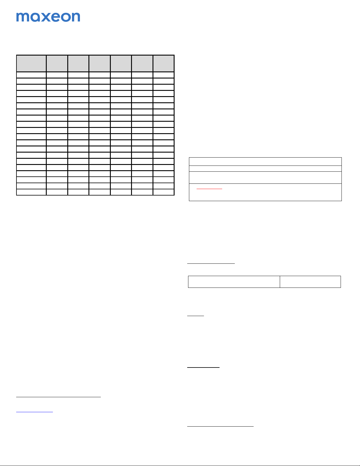
Specific information on module dimensions and the location of mounting and
grounding holes is provided in Appendix. The system installer is responsible for
the determination of location-specific load requirements.
It should be noted that watertightness is not ensured by Maxeon, therefore, if
water management is required, the mounting system should be designed
accordingly.
The module is only CSA Listed for use when its factory frame is fully intact. Do
not remove or alter the module frame, and do not create additional mounting
holes because doing so may compromise the integrity of the frame.
Modules may be mounted using the following methods only:
1) Frame Holes: Secure the module to the structure using the factory
mounting holes. Four 1/4″stainless steel bolts, with nuts, washers, and lock
washers are recommended per module; tightened to a min. torque of 10 in-
lb. This method has been certified by a third-party organization according to
UL 1703. For frame hole mounting, modules must be secured using the
holes shown in Appendix.
2) Clamps: Mount the module with the opposite clamps on the longer and/or
shorter sides of the module. Installers should ensure the clamps are of
sufficient strength to allow for the maximum design pressure of the
module. Clamps are not provided by Maxeon. Clamps that secure to the top
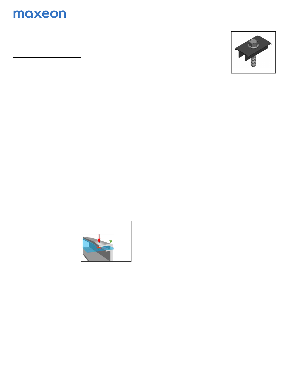
of the frame must not deform the top flange. Clamps must apply force
collinear with the ‘wall’ of the
module frame and not only to the
top flange. Clamps or installation
procedures that put excessive
force on the top flange will
deform the frame, void the
module warranty and risk glass
breakage. Figure 1a illustrates
locations for top frame clamp
force. When clamping to the
module frame, torque should never exceed 132 in-lbs (15 Nm) to reduce
chances of frame deformation and/or glass breakage. If the clamp
manufacturer recommends a specific torque value which is lower than 132
in-lbs (15 Nm), the installer should use the clamp manufacturer’s torque
value. If the clamp manufacturer recommends a specific torque value
which is higher than 132 in-lbs (15 Nm), the installer should contact the
clamp manufacturer for acceptance of the 132 in-lbs (15 Nm) maximum
torque value or to find alternative clamps. A calibrated torque wrench must
be used. Mounting systems should be evaluated for compatibility before
installing specially when the system is not using Clamps.
Minimum clamp width allowance is ≥35mm, and for corner clamping the
minimum clamp width is: ≥50mm. Clamps should not be in contact with the
front glass and clamps should not deform the frame.
Maxeon does not recommend nor endorse the application on the modules
of clamps which, as part of their grounding or earthing function, have teeth
or claw features (see Figure 2) which may, individually or cumulatively,
cause the module breakage due to (and without limitation):
i. the grounding features touching the
front glass which is incorporated into
the module due to the position of such
grounding feature,
ii. the shape, the position or the number
of the grounding features deforming
the module top frame, or
iii. the clamp being over-torqued during
the installation.
Maxeon shall not be liable for any damages or losses whatsoever arising
from the use by the Installer of any such clamps on its modules, and
disclaims all warranties, express or implied, applicable to those modules
should they be damaged in any way by such clamps. Therefore, the use of
the above mentioned clamps by the Installer is at the Installer's sole risks.
5.3 Ground Mount Applications for Bifacial modules
Various environmental and installation parameters affect bifacial gain. Albedo is a
measure of the amount of light reflected from the ground surface. A higher
albedo factor will increase irradiance on the backside and result in higher bifacial
gain of the module. The surface conditions, month of the year, time of day, GHI
and DNI both influence the amount of incident rearside irradiance.
Maxeon recommends to check with solar module mounting hardware supplier in
order to determine the Structure Shading factor of your particular installation.
The Structure Shading Factor varies with racking system design, irradiance,
albedo and height of module installation above ground and has an overall impact
on the rear side irradiance mismatch.
The Rearside mismatch losses are proportional to the albedo, height of the
modules above ground and structure shading factor. The irradiance non-
uniformity on the rearside results in mismatch generally as the albedo increases
and installation height of the modules are lower to the ground.
5.4 Rooftop Applications for Bifacial modules
Bifacial modules use direct, reflected or diffuse sunlight at the rearside to
generate additional power. Therefore, it is recommended to use bifacial modules
installed on flat roof applications.
In order to maximize the bifacial gain at the rooftop applications the following
parameters listed below should be considered:
•Surface Albedo
•Roof Integrity
•Module Tilt Angle
•Module Elevation
•Structural Backside Shading
The bifacial modules can be mounted both landscape or portrait orientation as
shown in Appendix section.
When installing a bifacial module on a roof, ensure that the roof construction and
the structural load calculations of the building are suitable.
Bifacial gain tends to be most effective with a higher tilt angle.
As the tilt angle and the module elevation from the underlying surface increases,
more reflected light and diffuse light can be captured by the module.
The mounting rails shall be designed to limit the rear side shading as much as
possible.
5.5 Bifacial Electrical Considerations
The overall electrical bifacial gain is determined by the combination of surface
albedo, irradiance, module tilt angle, shading losses from the rearside, rearside
mismatch and module elevation above ground. Please refer to the Maxeon
datasheet for the electrical outputs with respect to the overall bifacial gain.
Please utilize a suitable performance software package to simulate the overall
bifacial gain
5.6 Handling of Modules during Installation
Do not place modules face forward in direct contact with abrasive surfaces like
roofs, driveways, wooden pallets, railings, stucco walls, etc…
The module front surface glass is sensitive to oils and abrasive surfaces, which
may lead to scratches and irregular soiling.
Force must not deform
top frame flange or
glass may break
Figure 1a: Clamp Force Locations
Force can
be applied
in line with
frame wall
Fi
ure 2